EP1635517A1 - Procede de communication radio par paquets - Google Patents
Procede de communication radio par paquets Download PDFInfo
- Publication number
- EP1635517A1 EP1635517A1 EP20040746380 EP04746380A EP1635517A1 EP 1635517 A1 EP1635517 A1 EP 1635517A1 EP 20040746380 EP20040746380 EP 20040746380 EP 04746380 A EP04746380 A EP 04746380A EP 1635517 A1 EP1635517 A1 EP 1635517A1
- Authority
- EP
- European Patent Office
- Prior art keywords
- data
- packets
- data packets
- transmission
- transmitted
- Prior art date
- Legal status (The legal status is an assumption and is not a legal conclusion. Google has not performed a legal analysis and makes no representation as to the accuracy of the status listed.)
- Granted
Links
Images


Classifications
-
- H—ELECTRICITY
- H04—ELECTRIC COMMUNICATION TECHNIQUE
- H04W—WIRELESS COMMUNICATION NETWORKS
- H04W28/00—Network traffic management; Network resource management
- H04W28/02—Traffic management, e.g. flow control or congestion control
- H04W28/06—Optimizing the usage of the radio link, e.g. header compression, information sizing, discarding information
-
- H—ELECTRICITY
- H04—ELECTRIC COMMUNICATION TECHNIQUE
- H04B—TRANSMISSION
- H04B7/00—Radio transmission systems, i.e. using radiation field
- H04B7/02—Diversity systems; Multi-antenna system, i.e. transmission or reception using multiple antennas
-
- H—ELECTRICITY
- H04—ELECTRIC COMMUNICATION TECHNIQUE
- H04L—TRANSMISSION OF DIGITAL INFORMATION, e.g. TELEGRAPHIC COMMUNICATION
- H04L47/00—Traffic control in data switching networks
- H04L47/10—Flow control; Congestion control
- H04L47/36—Flow control; Congestion control by determining packet size, e.g. maximum transfer unit [MTU]
-
- H—ELECTRICITY
- H04—ELECTRIC COMMUNICATION TECHNIQUE
- H04W—WIRELESS COMMUNICATION NETWORKS
- H04W28/00—Network traffic management; Network resource management
- H04W28/02—Traffic management, e.g. flow control or congestion control
- H04W28/10—Flow control between communication endpoints
- H04W28/14—Flow control between communication endpoints using intermediate storage
-
- H—ELECTRICITY
- H04—ELECTRIC COMMUNICATION TECHNIQUE
- H04W—WIRELESS COMMUNICATION NETWORKS
- H04W28/00—Network traffic management; Network resource management
- H04W28/02—Traffic management, e.g. flow control or congestion control
- H04W28/04—Error control
-
- H—ELECTRICITY
- H04—ELECTRIC COMMUNICATION TECHNIQUE
- H04W—WIRELESS COMMUNICATION NETWORKS
- H04W74/00—Wireless channel access
Definitions
- the present invention relates to a wireless packet communication method for transmitting a plurality of data packets simultaneously between two wireless stations (hereinafter STAs) using a plurality of radio channels and Multiple Input Multiple Output (hereinafter MINO). More particularly, the present invention relates to a wireless packet communication method for generation of a plurality of data packets to be transmitted simultaneously.
- STAs wireless stations
- MINO Multiple Input Multiple Output
- a radio channel to be used is determined in advance. Prior to transmission of data packets, carrier sense is performed to detect whether or not that radio channel is idle. Only when that radio channel is idle, one data packet is transmitted.
- This management process enables a plurality of STAs to share one radio channel in a staggered manner ((1) IEEE802.11 "MAC and PHY Specification for Metropolitan Area Networks," IEEE 802.11, 1998, (2) "Low-powered Data Communication System/Broadband Mobile Access Communication System (CSMA) Standard, ARIB SDT-T71 version 1.0, Association of Radio Industries and Businesses, settled in 2000).
- CSMA Data Communication System/Broadband Mobile Access Communication System
- MIMO technique Kurosaki et al., "1 00Mbit/s SDM-COFDM over MIMO Channel for Broadband Mobile Communications", Technical Reports of the Institute of Electronics, Information and Communication Engineers, A P 2001-96, RCS2001-135(2001-10)
- MIMO technique different data packets are transmitted from a plurality of antennas on the same radio channel at the same time.
- the data packets transmitted at the same time on the same radio channel are received by digital signal processing that can deal with the difference in propagation coefficients of the respective data packets received by a plurality of wireless antennas in an opposed STA.
- a MIMO number is determined in accordance with the propagation coefficients and the like.
- each STA has a plurality of wireless network interfaces and can use a plurality of radio channels
- different radio channels can be used between a plurality of STAs.
- improvement of the throughput is promising, as compared with communication performed by time-dividing one radio channel.
- the case is considered where the center frequencies of radio channels #1 and #2 are close to each other and the transmission time is different between data packets that are transmitted simultaneously from the radio channels #1 and #2, as shown in Fig. 28.
- the data packet transmitted from the radio channel #1 is shorter.
- the radio channel #1 may not receive the ACK packet because of leakage power from the radio channel #2. In this situation, the throughput cannot be improved even if transmission is carried out by using a plurality of radio channels at the same time.
- the data size of a data frame input from a network is not constant.
- the packet time length (transmission time) of each data packet also changes. Therefore, even when a plurality of data packets are transmitted at the same time, as shown in Fig. 28, it is highly likely that a packet time length difference occurs between the data packets and causes a failure in the receiving of the ACK packet.
- a data frame input from a wired network e.g., Ethernet (registered trademark) frame
- a MAC Media Access Control
- one data frame is converted into one MAC frame from which one data packet is generated. Therefore, even if the data size of a data field in a data frame is small, that data frame is converted into one MAC frame and is transmitted as one data packet (wireless packet).
- the maximum size of the data field of a MAC frame in accordance with IEEE802.11 Standard is 2296 bytes
- the data size of the data field of an Ethernet (registered trademark) frame that is typically used as a data frame is limited to 1500 bytes. Therefore, even if the Ethernet (trademark) frame has the maximum size, that Ethernet frame has some leftover in the maximum size (2296 bytes) of the data field of the MAC frame. That is, the conventional system does not effectively use the maximum data size that can be transmitted in one MAC frame, and has a limitation in the improvement of the throughput.
- Fig. 29 shows an exemplary configuration of a wireless LAN system.
- a mobile terminal (address: S1) 11, a server (address: S2) 12, and a server (address: S3) 13 are connected through an access point (hereinafter AP) (address: AP) 10.
- the mobile terminal 11 and the AP 10 are connected to each other through a wireless line on which wireless packets are transmitted.
- the AP 10 and the servers 12 and 13 are connected through a router and the Internet. Ethernet (registered trademark) frames are transmitted between them.
- a transmission direction from the servers 12 and 13 to the mobile terminal 11 is called as a "downlink”
- a transmission direction from the mobile terminal 11 to the servers 12 and 13 is called as an "uplink".
- Fig. 30 shows a frame format for the downlink of the wireless LAN system.
- an Ethernet frame transmitted from the server 12 or 13 to the AP 10 contains a header, a frame body, and FCS.
- a destination address DA and a source address SA are set to "S1" and "S2", respectively.
- the frame body accommodates an IP packet for which the destination address DA and the source address SA are set to "S1" and "S2", respectively.
- the Ethernet frame transmitted from the server 12 or 13 is converted into a wireless packet in the AP 10 and is transmitted to the mobile terminal 11.
- the wireless packet contains a MAC header, a frame body, FCS, and the like.
- "S1" is set as a destination address DA in a PHY layer
- "AP” is set as BSS (Basic service set) ID corresponding to a source address in the PHY layer
- "S2" is set as a source address SA.
- the frame body accommodates an IP packet for which "S1" is set as the destination address DA and "S2" is set as the source address SA.
- Fig. 31 shows a frame format for the uplink of the wireless LAN system.
- the mobile terminal 1 1 generates an IP packet to the server 12 or 13.
- "S2" is set as a destination address DA
- "S1" is set as a source address SA.
- a wireless packet transmitted from the mobile terminal 1 1 to the AP 10 contains a MAC header, a frame body, FCS, and the like.
- BSSID corresponding to a destination address in the PHY layer is set to "AP”
- a source address SA in the PHY layer is set to "S1”
- a destination address DA is set to "S2”.
- the frame body accommodates the IP packet for which the destination address DA is set to "S2" and the source address SA is set to "S1".
- the wireless packet transmitted from the mobile terminal 11 is converted into an Ethernet frame in the AP 10 and is transmitted to the server 12 or 13.
- the Ethernet frame contains a header, a frame body, and FCS.
- a destination address DA and a source address SA are set to "S2" and "S1", respectively.
- the frame body accommodates the IP packet for which the destination address DA and the source address SA are set to "S2" and "S1", respectively.
- a conventional AP generates one wireless packet from one Ethernet frame to the mobile terminal and transmits that wireless packet on the downlink of the PHY layer from the AP to the mobile terminal. From a viewpoint of improving transmission efficiency, a method is considered to be effective that generates one or more wireless packets from a plurality of Ethernet frames transmitted from a plurality of servers to the same mobile terminal and then transmits those one or more wireless packets in one lump.
- a conventional mobile terminal generates one wireless packet from one IP packet to a server and transmits that wireless packet on the uplink of the PHY layer from the mobile terminal to the AP.
- a method is considered to be effective that generates one or more wireless packets from a plurality of IP packets to the same server and transmits those one or more wireless packets in one lump.
- IP packets to the same server can be found by referring to their destination addresses DA. It is also possible to find whether or not a plurality of IP packets to different servers go through the same AP by checking their destination addresses DA against the AP address.
- AP access point
- a wireless packet communication method for transmitting X data packets simultaneously between two STAs by using a plurality of radio channels that are determined to be idle by carrier sense or using a radio channel that is determined to be idle and MIMO, or for transmitting X data packets simultaneously between two STAs by using both the above transmission methods where X corresponds to a total number of MIMOs of the plurality of radio channels is provided.
- the wireless packet communication method is for fragmenting a data part extracted from a data field of one data frame to be transmitted to generate X data blocks that have data fields equal to or smaller than Dmax and the same packet time length (data size, transmission time), generates X data packets by adding a header field containing control information such as destination information and an FCS field containing an error checking code to each of the X data blocks, and transmits the X data packets simultaneously.
- a maximum data size of the X data packets is set to a value obtained by (Dmax x a transmission rate of a corresponding line/a reference transmission rate); a data part extracted from a data field of one data frame to be transmitted is fragmented in accordance with transmission rates of respective lines to generate X data blocks having data fields equal to or smaller than the maximum data size of each line and having the same packet time length (transmission time); and X data packets are generated by adding a header field containing control information such as destination information and an FCS field containing an error checking code to each of the X data blocks, and are transmitted simultaneously.
- a plurality of data packets that are equal to or smaller than the maximum data size and have the same packet time length can be generated from one data frame, and can be transmitted simultaneously by using a plurality of radio channels, or one radio channel and MIMO, or a plurality of radio channels and MIMO.
- X data blocks having data fields equal to or smaller than Dmax and a same packet time length are generated by connecting and dividing data parts extracted from data fields of a plurality of data frames to be transmitted; and X data packets are generated by adding a main header field containing control information such as destination information and an FCS field containing an error checking code to each of the X data blocks, and are transmitted simultaneously.
- a maximum data size of the X data packets is set to a value obtained by (Dmax x a transmission rate of a corresponding line/the reference transmission rate);
- X data blocks having data fields equal to or smaller than the maximum data size in each line and the same packet time length (transmission time) are generated by connecting data parts extracted from data fields of a plurality of data frames to be transmitted and dividing the connected data parts in accordance with transmission rates of respective lines; and
- X data packets are generated by adding a main header field containing control information such as destination information and an FCS field containing an error checking code to each of the X data blocks, and are transmitted simultaneously.
- a plurality of data packets that are equal to or smaller than the maximum data size and have the same packet time length can be generated by connecting and dividing (cutting and pasting) a plurality of data frames, and can be transmitted simultaneously by using a plurality of radio channels, or one radio channel and MIMO, or a plurality of radio channels and MIMO.
- X data series having data fields equal to or smaller than Dmax are generated by aggregating data parts extracted from data fields of a plurality of data frames to be transmitted;
- X data blocks having the same packet time length (data size, transmission time) are generated by adding dummy data to a data series of the X data series except one having a largest data size; and
- X data packets are generated by adding a header field containing control information such as destination information and an FCS field containing an error checking code to each of the X data blocks, and are transmitted simultaneously.
- a maximum data size of the X data packets is set to a value obtained by (Dmax x a transmission rate of a corresponding line/the reference transmission rate);
- X series having data fields equal to or smaller than the maximum data size in each line are generated by aggregating data parts extracted from data fields of a plurality of data frame to be transmitted;
- X data blocks having the same packet time length (transmission time) are generated by adding dummy data to a data series the X data series except one having a largest packet time length (transmission time); and
- X data packets are generated by adding a header field containing control information such as destination information and an FCS field containing an error checking code to each of the X data blocks, and are transmitted simultaneously.
- a plurality of data packets that are equal to or smaller than the maximum data size and have the same packet time length can be generated by aggregating a plurality of data frames so as not to exceed the maximum data size, and can be transmitted simultaneously by using a plurality of radio channels, or one radio channel and MIMO, or a plurality of radio channels and MIMO.
- the transmission rates of the transmission media are made the same as a smallest one of the transmission rates.
- the data series are generated by accepting the data frames to be transmitted in order and assigning the data frames to the respective transmission media until a total data size reaches a largest size not exceeding the maximum data size Dmax.
- the data series are generated by accepting the data frames to be transmitted in order, assigning one data frame to each of the transmission media, and repeating the assignment of one data frame until a total data size reaches a largest size that is equal to or smaller than the maximum data size Dmax.
- the data series are generated by accepting the data frames to be transmitted in order, assigning one data frame to each of the transmission media, and repeating the assignment of one data frame such that a next data frame is assigned to one of the transmission media that has a smallest data size of assigned data frames until a total data size reaches a largest size that is equal to or smaller than the maximum data size Dmax.
- the data series are generated by employing one of the methods recited in claims 8 to 10 so that a total number of accommodated data frames is to be a maximum.
- the data series are generated by accepting the data frames to be transmitted in order and assigning the data frames to the respective transmission media until a total data size reaches a maximum value equal to or smaller than the maximum data size.
- the data series are generated by accepting the data frames to be transmitted in order, assigning one data frame to each of the transmission media, and repeating the assignment of one data frame until a total data size reaches a largest size that is equal to or smaller than the maximum data size.
- the data series are generated by accepting the data frames to be transmitted in order, assigning one of the data frames to one of the transmission media, repeating the assignment of one data frame such that a next data frame is assigned to one of the transmission media that has a smallest data size of assigned data frames until a total data size reaches a largest size that is equal to or smaller than the maximum data size.
- the data series are generated by employing one of the methods recited in claims 12 to 14 so that a total number of accommodated data frames is to be a maximum.
- the data series are generated to contain sub-headers for identifying the data frames, respectively.
- the X data packets are generated by the method recited in claim 1 in the case where a number of data frames to be transmitted is 1; the X data packets are generated by the method recited in claim 3 or 5, in the case where the number of the data frames to be transmitted is 2 or more and it is possible to generate data packets equal to or smaller than a maximum data size in each line by the connection and division as recited in claim 3 or the aggregation as recited in claim 5; and the X data packets are generated by the method recited in claim 1, in the case where the number of the data frames to be transmitted is 2 or more and it is impossible to generate the data packets equal to or smaller than the maximum data size in each line by the connection and division as recited in claim 3 or aggregation as recited in claim 5.
- a maximum data size of the X data packets is set to a value obtained by (Dmax x a transmission rate of a corresponding line/the reference transmission rate); the X data packets are generated by the method recited in claim 2 in the case where a number of data frames to be transmitted is 1; the X data packets are generated by the method recited in claim 4 or 6, in the case where the number of the data frames to be transmitted is 2 or more and it is possible to generate data packets equal to or smaller than a maximum data size in each line by the connection and division as recited in claim 4 or the aggregation as recited in claim 6; and the X data packets are generated by the method recited in claim 2, in the case where the number of the data frames to be transmitted is 2 or more and it is impossible to generate the data packets equal
- X data packets that are generated after simultaneous transmission of the X data packets are transmitted continuously without performing carrier sense, until a time corresponding to a transmission time of data packets generated from one data frame before being fragmented passes.
- X data packets that are generated after simultaneous transmission of the X data packets are transmitted simultaneously consecutively X times without performing carrier sense.
- any one of claims 1 to 6 when one of the two STAs is an AP and the other is a mobile terminal, one or more data frames are selected from data frames addressed to a same mobile terminal in a transmission buffer of the AP within a range in which the one or more data frames are able to be accommodated in data packets to be transmitted simultaneously, the transmission buffer storing data frames transmitted to the mobile terminal from a device connected to the AP; a source address of the device connected to the AP is added to each of frame bodies of the one or more data frames and the frame bodies are connected; the X data packets are generated by adding a MAC header to each of data blocks obtained by dividing the connected frame bodies by a number of simultaneous transmissions, and are transmitted simultaneously.
- one or more IP packets are selected from IP packets addressed to a same AP in a transmission buffer of the mobile terminal within a range in which the one or more IP packets are able to be accommodated in data packets to be transmitted simultaneously, the transmission buffer being storing IP packets to be transmitted to a device connected to the AP; a destination address of the device connected to the AP is added to each of the one or more IP packets and the one or more IP packets are connected; and the X data packets are generated by adding a MAC header to each of data blocks obtained by dividing the connected frame bodies by a number of simultaneous transmissions, and are transmitted simultaneously.
- any one of claims 1 to 6 when one of the two STAs is an AP and the other is a mobile terminal, one or more data frames are selected and aggregated from data frames addressed to a same mobile terminal in a transmission buffer of the AP within a range in which the one or more data frames are able to be accommodated in data packets to be transmitted simultaneously, the transmission buffer storing data frames transmitted to the mobile terminal from a device connected to the AP; a source address of the device connected to the AP is added to each of frame bodies of the selected data frames; a MAC header is further added to each of the frame bodies of the selected data frames to generate the X data packets; and the X data packets are transmitted simultaneously.
- one of the two STAs is an AP and the other is a mobile terminal
- one or more IP packets are selected and aggregated from IP packets addressed to a same AP in a transmission buffer of the mobile terminal within a range in which the selected IP packets are able to be accommodated in data packets to be transmitted simultaneously, the transmission buffer storing IP-packets to be transmitted to a device connected to the AP; a destination address of the device connected to the AP is added to each of the selected IP packets; a MAC header is further added to each of the selected IP packets to generate the X data packets; and the X data packets are transmitted simultaneously.
- a communication device is connected to each of the two STAs.
- the one STA transfers data frames that are accumulated in a transmission buffer and are transmitted from a source device connected to the one STA to a destination device connected to the other STA, the one STA generates data packets by the method recited in any one of claims 28 to 33 and transmits the data packets in one lump or simultaneously, for data frames addressed to the other STA.
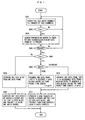
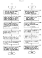
- Fig. 1 is a flowchart according to a first embodiment of the present invention.
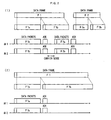
- Fig. 2 shows an exemplary operation in the first embodiment of the present invention.
- a transmission-standby data frame in a transmission buffer in the following description is a data frame transmitted between two STAs.
- An idle radio channel is searched from all available radio channels by carrier sense (S001).
- the number of the detected idle channels is assumed to be N.
- N the number of the detected idle channels.
- it is searched whether or not there is a transmission-standby data frame in a transmission buffer (S002 and S003).
- S004 the procedure goes back to the carrier sense.
- N 1, one data block is generated from one data frame (S005 and S006).
- a header field containing control information such as destination information and an FCS (Frame Check Sequence) part containing an error checking code (hereinafter, referred to as "a header and the like") are added to the thus generated data block, thereby generating a data packet.
- the data packet is transmitted by using one radio channel (S007).
- a transmission rate of each radio channel may be fixed in advance, or may be set on a case-by-case basis by selecting one of a plurality of transmission rates determined in advance, for example, based on the quality of a wireless line.
- the transmission rates of the respective radio channels are checked (S008). At this time, the number X of data packets that are to be transmitted simultaneously is determined (X ⁇ N).
- X ⁇ N the number of data packets that are to be transmitted simultaneously.
- a data part of one data frame is fragmented into X so as to generate X data blocks having the same packet time length (S009).
- two radio channels are idle, for example, two data packets can be transmitted at the same time.
- the data part of one data frame is equally fragmented so as to generate two data blocks.
- the data part of one data frame is fragmented into X at a size ratio corresponding to the transmission rates, so as to generate X data blocks having the same packet time length (transmission time) (S010).
- S010 packet time length
- the data part of one data frame is fragmented at a packet size ratio of 1:2 so as to generate two data blocks, as shown in Fig. 2(2).
- X data packets are generated by adding a header and the like to each of the X data blocks.
- the thus generated X data packets are transmitted simultaneously by using X radio channels (S011).
- the data packets transmitted simultaneously have the same packet time length, as shown in Fig. 2. Therefore, transmission of the X data packets terminates at the same time.
- ACK packets after that transmission can be received without being affected by leakage power.
- a termination time of transmission of each data packet is different by a time corresponding to a difference of the packet time length.
- a time at which each ACK packet is received is different by the time corresponding to the difference of the packet time length.
- each ACK packet can be received without being affected by leakage power. In other words, it is not always necessary that the packet time lengths of the data packets to be transmitted simultaneously are strictly the same. The phrase "having the same packet time length" in the claims is written considering the above.
- Fig. 3 is a flowchart according to a second embodiment of the present invention.
- a smallest one of the transmission rates is selected as a common transmission rate (S012). In this case, it is not necessary to perform the process in Step S010 of the first embodiment.
- One data frame is fragmented into X in Step S009 so as to generate X data blocks having the same packet time length.
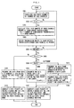
- Fig. 4 is a flowchart according to a third embodiment of the present invention.
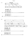
- Fig. 5 shows an exemplary operation in the third embodiment of the present invention. It is assumed that radio channels #1 and #2 are provided between two STAs. A transmission stand-by data packet in a transmission buffer in the following description is a data packet to be transmitted between those two STAs.
- a feature of the present embodiment is to use MIMO in the first embodiment.
- An idle radio channel is searched from all available radio channels by carrier sense (S001).
- the number of the detected idle channels is assumed to be N.
- a total number of MIMOs is calculated as "a number of simultaneous transmissions" (S002 and S101).
- S002 and S101 For simplification, it is assumed that the MIMO numbers of the respective radio channels are the same and the number of simultaneous transmissions is a product (NL) of the number N of the idle channels and the MIMO number L.
- transmission rates of the respective radio channels are checked (S008).
- the number X (X ⁇ NL) of data packets to be transmitted simultaneously is also determined.
- a data part of one data frame is fragmented into X so as to generate X data blocks having the same packet time length (S104). For example, when two radio channels are idle and the MIMO number L of each radio channel is 2, four data packets can be transmitted at the same time. Therefore, the data part of one data frame is equally fragmented to generate four data blocks, as shown in Fig. 5(1).
- transmission rates thereof are 6 Mbit/s and 12 Mbit/s, respectively, and the MIMO number L of each channel is 2
- the data part of one data frame is fragmented at a packet size ratio of 1:2
- each of the resultant data blocks is equally fragmented, thereby generating four data blocks, as shown in Fig. 5(2).
- transmission rates of respective transmission media for MIMO are different, it is only necessary to perform fragmentation in accordance with the transmission rates in a similar manner.
- X data packets are generated by adding a header and the like to each of the X data blocks.
- the X data packets are transmitted simultaneously by using ceil (X/L) radio channels and MIMO (S107), where ceil (x) represents the smallest integer equal to or larger than x (i.e., an integer obtained by rounding up x).
- ceil (x) represents the smallest integer equal to or larger than x (i.e., an integer obtained by rounding up x).
- ceil (x) represents the smallest integer equal to or larger than x (i.e., an integer obtained by rounding up x).
- the simultaneous transmission of the data packets terminates at the same time, because those data packets have the same packet time length, as shown in Fig. 5.
- ACK packets after that transmission can be received without being affected by leakage power.
- Fig. 6 is a flowchart according to a fourth embodiment of the present invention.
- Fig. 7 shows an exemplary operation in the fourth embodiment of the present invention.
- radio channels #1 and #2 are provided between two radio channels.
- a transmission stand-by data packet in a transmission buffer is a data packet transmitted between those two STAs.
- An idle radio channel is searched from all available radio channels by carrier sense (S001).
- the number of the detected idle channels is assumed to be N.
- it is then searched whether or not there is a transmission-standby data frame in the transmission buffer (S002 and S003).
- the procedure goes back to carrier sense.
- the procedure goes ahead (5004).
- the maximum size Dmax that can be transmitted in one MAC packet is determined, and a total of the maximum data size Dmax • X in the case where simultaneous transmission is performed using X radio channels is calculated.
- data parts of transmission-standby data frames are connected so as not to exceed the above total of the maximum data size (S201).
- the connected data frames are divided into X so as to generate X data blocks having the same packet time length (S202).
- the maximum size in each radio channel Dmax • Ri/Rmax is determined, assuming that a transmission rate of each radio channel is Ri (i is an integer from 1 to X), the maximum transmission rate is Rmax, and the maximum size of data that can be transmitted in one MAC packet is Dmax.
- the total of the maximum data size when simultaneous transmission is performed using X radio channels is calculated.
- data parts of transmission-standby data frames are connected so as not to exceed the above total of the maximum data size (S203).
- the connected data frames are divided into X at a size ratio corresponding to the transmission rates Ri, thereby generating X data blocks having the same packet time length (transmission time) (S204).
- X data packets are generated by adding a header and the like to each data block.
- the X data packets are transmitted simultaneously using X radio channels (S205).
- a process for generating two data packets from three data frames in the case where two radio channels have transmission rates of 12 Mbit/s and 24 Mbit/s, respectively, is now described with reference to Fig. 7.
- the three data frames contain a data part F1 of 500 bytes, a data part F2 of 1500 bytes, and a data part F3 of 1000 bytes, respectively.
- a data block of 3000 bytes is generated by connecting those data parts.
- the thus generated data block is divided at a packet size ratio of 1 :2, thereby generating a data block of 1000 bytes and a data block of 2000 bytes.
- a size ratio of data parts of two data packets generated from those two data blocks is 1:2, and is the same as a ratio of the transmission rates of the corresponding radio channels.
- the data packets require the same length of time for transmission, i.e., have the same packet time length. Therefore, ACK packets after the transmission of those data packets can be received without being affected by leakage power.
- Fig. 8 is a flowchart according to a fifth embodiment of the present invention.
- a feature of the present invention is to use MIMO in the fourth embodiment.
- An idle radio channel is searched from all available channels by carrier sense (S001).
- the number of the detected idle channels is assumed to be N.
- a total number of MIMOs of the respective radio channels is calculated as "a number of simultaneous transmissions" (S002 and S101).
- S002 and S101 For simplification, the description is made assuming that the MIMO numbers of the respective radio channels are the same and the number of simultaneous transmissions is a product (NL) of the number N of idle channels and the MIMO number L.
- transmission rates of the respective radio channels are also checked (S008).
- the maximum size Dmax that can be transmitted in one MAC packet is determined, and a total of the maximum data size Dmax • X in the case where X data packets are transmitted simultaneously by using the radio channels and MIMO is calculated.
- data parts of transmission stand-by data frames are connected so as not to exceed the above total of the maximum data size (S211).
- the connected data frames are divided into X, thereby generating X data blocks having the same packet time length (S212).
- the maximum size Dmax • Ri/Rmax for each transmission medium is determined, where a transmission rate of each of transmission media formed by radio channels and MIMO is Ri (i is an integer from 1 to X), the maximum transmission rate is Rmax, and the maximum size that can be transmitted in one MAC packet is Dmax. Then, the total of the maximum data size in the case where X data packets are transmitted simultaneously by using radio channels and MIMO is calculated. Data parts of the transmission stand-by data frames are connected so as not to exceed the total of the maximum data size (S213). The connected data frames are divided into N N at a size ratio corresponding to the transmission rates Ri, thereby generating N N data blocks (S214).
- X data packets are generated by adding a header and the like to each data block.
- the X data packets are transmitted simultaneously by using ceil (X/L) radio channels and MIMO (S216).
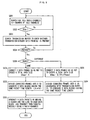
- Fig. 9 is a flowchart according to a sixth embodiment of the present invention.
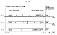
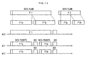
- Figs. 10 and 11 show exemplary operations in the sixth embodiment of the present invention.
- radio channels #1, #2, and #3 are provided between two STAs.
- a transmission stand-by data packet in a transmission buffer in the following description is a data packet transmitted between those two STAs. It is assumed that transmission rates of the respective radio channels are set to be the same.
- An idle radio channel is searched from all available radio channels by carrier sense (S001).
- the number of the detected idle channels is assumed to be N.
- it is then searched whether or not there is a transmission-standby data frame in the transmission buffer (S002 and S003).
- S002 and S003 When there is no transmission-standby data frame, the procedure goes back to carrier sense.
- the procedure goes ahead (S004).
- X (X ⁇ N) of data packets to be transmitted simultaneously is determined.
- N 1 by setting X to 1.
- X data blocks are generated by aggregating transmission-standby data frames in order (S301). Please note that the data frames are aggregated in such a manner that the data size of each data block does not exceed the maximum data size Dmax that can be transmitted in one MAC frame (e.g., 2296 bytes).
- Fig. 10 shows an example in which data frames 1 and 2 are assigned to the radio channel #1, data frames 3, 4, and 5 are assigned to the radio channel #2, and a data frame 6 is assigned to the radio channel #3. An assignment and management method for forming those data blocks will be described later.
- Step S303 for adding dummy data is omitted.
- X data packets are generated by adding a header and the like to each data block and are transmitted simultaneously by using X radio channels (S304).
- the data packets of the respective radio channels are transmitted at approximately the same time in a period from time t1 to time t2, and ACK packets can be received at approximately the same time in a period from time t3 to time t4, as shown in Fig. 10.
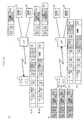
- Fig. 11 shows a method for assigning and managing data frames.
- Fig. 11(1) shows a method in which data frames accumulated in the transmission buffer are assigned to the radio channels in order from the first one of the data frames until the total data size in each radio channel reaches the largest size that does not exceed the maximum data size Dmax, thereby generating data blocks.
- the data frames 1 and 2 are assigned to the radio channel #1
- the data frames 3, 4, and 5 are assigned to the radio channel #2
- the data frame 6 is assigned to the radio channel #3. Please note that given correspondence between the radio channels and data blocks can be employed.
- Fig. 11(2) shows a method in which, starting from the first one of data frames accumulated in the transmission buffer, one of the data frames is assigned to one of the radio channels. This assignment to each of the radio channels is repeated until the total data size in each radio channel reaches the largest size that does not exceed the maximum data size Dmax. In this manner, data blocks are generated.
- the data frames 1, 2, and 3 are assigned to the radio channels #1, #2, and #3 in the first round, respectively.
- the data frames 4, 5, and 6 are assigned to the radio channels #1, #2, and #3 in the second round, respectively.
- the data frames 1 and 4 are assigned to the radio channel #1
- the data frames 2 and 5 are assigned to the radio channel #2
- the data frames 3 and 6 are assigned to the radio channel #3.
- the assignment of the data frame 5 passes the radio channel #2. Instead, the data frame 5 is assigned to the radio channel #3 and it is checked whether or not the data size in the radio channel #3 exceeds the maximum data size Dmax. This operation is repeated. In the case where the data frame 5 cannot be assigned to any of the wireless cannels, the assignment of the data frames ends with the assignment of the data frame 4.
- Fig. 11 (3) shows a method in which, starting from the first one of the data frames accumulated in the transmission buffer, one of the data frames is assigned to one of the radio channels, and a next data frame is assigned to one of the radio channels which has the smallest total data size of assigned data frames. The assignment of the next data frame is repeated until the total data size in each radio channel reaches the largest size that does not exceed the maximum data size Dmax. In this manner, data blocks are generated.
- the data frames 1, 2, and 3 are assigned to the radio channels #1, #2, and #3 in the first round, respectively; the following data frame, i.e. the data frame 4 is assigned to the radio channel #3; the following data frame, i.e., the data frame 5 is assigned to the radio channel #1; the following data frame, i.e., the data frame 6 is assigned to the radio channel #2; and the following data frame, i.e., the data frame 7 is assigned to the radio channel #3.
- the data frames 1 and 5 are assigned to the radio channel #1
- the data frames 2 and 6 are assigned to the radio channel #2
- the data frames 3, 4, and 7 are assigned to the radio channel #3.
- the assignment of the data frames ends with the assignment of the data frame 5.
- the assignment and management method shown in Fig. 11(3) allows for assignment of up to 7 data frames and therefore has the highest transmission efficiency among the aforementioned three assignment and management methods. However, this depends on the data sizes of the data frames accumulated in the transmission buffer. That is, it cannot be determined which one of the methods is the best. Therefore, for the data frames accumulated in the transmission buffer, the number of data frames that can be assigned by each of the three assignment and management methods may be compared with those by other methods and one of the assignment and management methods that can maximize the number of assigned data frames may be employed.
- the maximum size Dmax • Ri/Rmax in each radio channel may be determined assuming that a transmission rate of each radio channel is Ri, the maximum transmission rate is Rmax, and the maximum size that can be transmitted on each radio channel is Dmax.
- the process for aggregating the data frames may be performed for each radio channel.
- Fig. 12 is a flowchart according to a seventh embodiment of the present invention.
- a feature of the present embodiment is to use MIMO in the sixth embodiment.
- An idle radio channel is searched from all available channels by carrier sense (S001).
- the number of the detected idle channels is assumed to be N.
- a total number of MIMOs of the respective radio channels is calculated as "a number of simultaneous transmissions" (S002 and S101).
- S002 and S101 For simplification, the description is made assuming that the MIMO numbers of the respective radio channels are the same and the number of simultaneous transmissions is a product (NL) of the number N of idle channels and the MIMO number L.
- the number X (X ⁇ NL) of data packets to be transmitted simultaneously is determined.
- N 1 and L ⁇ 2) or N ⁇ 2
- the transmission-standby data frames are connected in order so as to generate X data blocks (S301). This connection of the data frames is performed in such a manner that the data size of each data block does not exceed the maximum data size Dmax that can be transmitted in one MAC frame (e.g., 2296 bytes).
- Step S303 for adding dummy data is omitted.
- X data packets are generated by adding a header and the like to each of the data blocks. The thus generated X data packets are transmitted simultaneously using ceil (X/L) radio channels and MIMO (S305).
- the maximum size Dmax • L • Ri/Rmax for each transmission medium is determined assuming that a transmission rate of each transmission medium is Ri, the maximum transmission rate is Rmax, and the maximum size of data that can be transmitted by each transmission medium is Dmax.
- the process for aggregating the data frames is performed for each transmission medium.
- Fig. 13 is a flowchart according to an eighth embodiment of the present invention.
- a procedure is described which selects a frame fragmentation method described in the first to third embodiments or a frame patching method described in the fourth and fifth embodiments in accordance with the number K of transmission-standby data frames.
- Step S001 to S004 it is determined whether the number K of the data frames is 1 or 2 or more (S401).
- the number K of the data frames is 1, X data packets are generated by fragmenting one data frame based on the frame fragmentation method described in the first to third embodiments. The thus generated X data packets are then transmitted simultaneously (S402).
- X data packets are generated by dividing one data frame based on the frame division method described in the first to third embodiments.
- the thus generated X data packets are transmitted simultaneously (S404 and S402). For example, when a ratio of transmission rates of two radio channels is 1:9 and there are two data frames of 1500 bytes, one of two data frames of 300 bytes and 2700 bytes that are generated by the connection and division exceeds Dmax (2296 bytes). Therefore, those two generated data frames cannot be transmitted simultaneously. Instead, data packets (150 bytes and 1350 bytes) generated by dividing each data frame into two are transmitted simultaneously.
- X data packets are generated by the frame patching method described in the fourth and fifth embodiments and are transmitted simultaneously, when the number N of the idle channels is 2 or more (S405 and S406).
- the number N of the idle channels is 1, only one data packet can be transmitted.
- data parts of transmission-standby data frames are aggregated so as not to exceed the maximum data size Dmax, thereby generating one data packet.
- the thus generated one data packet is transmitted by using one radio channel (S407).
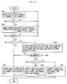
- Fig. 14 is a flowchart according to a ninth embodiment of the present invention.
- a procedure is described which selects the frame fragmentation method described in the first to third embodiments or a frame aggregation method described in the sixth and seventh embodiments in accordance with the number K of transmission stand-by data frames.
- Steps S001 to S004 it is determined whether the number K of the data frames is 1 or 2 or more (S401).
- the number K of the data frames is 1, X data packets are generated by fragmenting one data frame based on the frame fragmentation method described in the first to third embodiments and are transmitted simultaneously (S402).
- the number K of the data frames is 2 or more
- data packets are generated from X data frames, respectively, and are transmitted simultaneously (S412 and S413). For example, when all of a plurality of data packets have sizes of 1200 bytes or more, it is not possible to connect a plurality of data packets within Dmax (2296 bytes). Therefore, data packets having the same packet time length are generated from those data frames and are transmitted simultaneously.
- X data packets are generated by the frame aggregation method described in the sixth and seventh embodiments and are transmitted simultaneously, when the number N of the idle channels is 2 or more (S414 and S415).
- the number N of the channels is 1, only one data packet can be transmitted.
- data parts of transmission-standby data frames are aggregated so as not to exceed the maximum data size Dmax, thereby generating one data packet.
- the thus generated one data packet is transmitted by using one radio channel (S416).
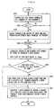
- Fig. 1 5 is a flowchart according to the tenth embodiment of the present invention.
- Fig. 16 shows an exemplary operation in the tenth embodiment of the present invention. It is assumed that two radio channels #1 and #2 are provided between two STAs. In the following description, transmission stand-by data packets in a transmission buffer are data packets transmitted between those two STAs.
- T is set to 0 in default setting (S500).
- An idle radio channel is searched from all available radio channels by carrier sense (S001).
- the number of the detected idle channels is assumed to be N.
- N When one or more idle radio channels are detected, it is searched whether or not there is a transmission-standby data frame in the transmission buffer (S002 and S003).
- S002 and S003 When no transmission-standby data frame is present, the procedure goes back to carrier sense.
- S004 When there is a transmission-standby data frame, the procedure goes ahead (S004).
- N 1, one data packet is generated from one data frame and is then transmitted by using one radio channel, as in the first embodiment. However, this case is not shown in the drawings.
- N X data packets are generated from one data frame by the frame fragmentation method described in the first to third embodiments, and are then transmitted simultaneously (S501). Moreover, a transmission time T of those data packets generated from the data frame is calculated and a timer is made to start (S502 and S503). Then, the procedure goes back to Step S003 and next data packets are transmitted simultaneously by using the currently idle channel without performing carrier sense. The transmission of the next data packets is continuously performed until the time T passes after the start of the timer (S504).
- continuous transmission of data packets can be performed in accordance with a Group ACK procedure that is discussed in IEEE802.11 TGe, for example.
- Fig. 17 is a flowchart according to the eleventh embodiment of the present invention.
- the present embodiment has a feature that the number of consecutive transmissions that corresponds to the number of fragmentation X is employed as a period of consecutive transmissions.
- the number of consecutive transmissions is assumed to be C and C is set to 0 in default setting.
- X data packets are generated from one data frame by the frame fragmentation method described in the first to third embodiments, and are transmitted simultaneously (S501).
- the number of consecutive transmissions C is incremented (S511).
- the procedure goes back to Step 5003 and next data packets are continuously transmitted simultaneously by using the currently idle channel without performing carrier sense. This transmission is repeated until C reaches X (S512).
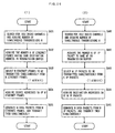
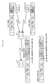
- Fig. 18 is flowcharts according to a twelfth embodiment of the present invention.
- Fig. 18(1) shows a procedure of an AP in a downlink
- Fig. 18(2) shows a procedure of a mobile terminal in an uplink
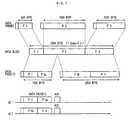
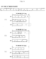
- Fig. 19 shows exemplary frame formats for the downlink and the uplink in the twelfth embodiment.
- the AP searches an idle radio channel by carrier sense (S61 1). Then, the AP acquires the number K of Ethernet frames that are the same in a destination address (an address of a mobile terminal) as the first Ethernet frame in the transmission buffer (S612). Then, the AP selects N (1 ⁇ N ⁇ K) Ethernet frames that are to be transmitted in one lump from the K Ethernet frames within a range in which the selected Ethernet frames can be accommodated in one wireless packet (S613). The AP also acquires a source address (SA) from a header of each of the N Ethernet frames (S614).
- SA source address
- the AP adds control information to a frame body (IP packet) of each of the N Ethernet frames.
- the control information contains the source address SA of the corresponding Ethernet frame.
- the AP generates a wireless packet that contains a frame body obtained by aggregating the frame bodies of the N Ethernet frames with the control information added thereto and also contains a MAC header and FCS added to the frame body.
- the MAC header contains a destination address DA, BSSID, and a source addresses SA.
- the AP transmits the thus generated wireless packet (S615).
- the frame body of that wireless packet is generated so as not to exceed the maximum data size that can be transmitted in one MAC frame (e.g., 2296 bytes).
- Fig. 19(1) shows an example in which an AP 10 generates one wireless packet from Ethernet frames transmitted from servers 12 and 13 and transmits it in one lump.
- an identifier for specifying a frame format "S1" as the destination address DA, "AP” as BSSID, and a given address (e.g., AP) as the source address SA are set.
- the frame body of the wireless packet accommodates the frame body (IP packet) of the Ethernet frame transmitted from the server 12 with its source address SA (S2) added thereto and the frame body (IP packet) of the Ethernet frame transmitted from the server 13 with its source address SA (S3) added thereto.
- the mobile terminal searches an idle radio channel by carrier sense, when IP packets are accumulated in the transmission buffer (S621). Then, the mobile terminal acquires the number K of IP packets in the transmission buffer that are sent to the same AP (S622). The mobile terminal selects N (1 ⁇ N ⁇ K) IP packets that are to be transmitted in one lump from the K IP packets within a range in which the selected IP packets can be accommodated in one wireless packet (S623). The mobile terminal acquires a destination address DA from an IP header of each of the N IP packets (S624). Then, the mobile terminal adds control information to a frame body of each of the N IP packets. The control information contains the destination address DA of the corresponding IP packet.
- the mobile terminal then generates a wireless packet that contains a frame body obtained by aggregating the N frame bodies with the control information added thereto and also contains a MAC header and FCS added to the frame body.
- the MAC header contains BSSID, a source address SA, and a destination address DA.
- the mobile terminal transmits the thus generated wireless packet (S625).
- the frame body of that wireless packet is generated so as not to exceed the maximum data size that can be transmitted in one MAC frame (e.g., 2296 bytes).
- Fig. 19(2) shows an example in which one wireless packet is generated from IP packets to servers 12 and 13 in a mobile terminal 11 and is transmitted in one lump.
- an identifier for specifying a frame format "AP" as BSSID, "S1" as the source address SA, and a given address (e.g., AP) as the destination address DA are set.
- the frame body of the wireless packet accommodates the IP packet to the server 12 with its destination address DA (S2) added thereto and the IP packet to the server 13 with its destination address DA (S3) added thereto.
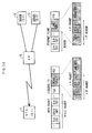
- Fig. 20 includes flowcharts according to the thirteenth embodiment of the present invention.
- Fig. 20(1) shows a procedure of an AP in a downlink
- Fig. 20(2) shows a procedure of a mobile terminal in an uplink
- Fig. 21 shows frame formats for the downlink and the uplink in the thirteenth embodiment.
- the AP searches an idle radio channel by carrier sense and acquires a number of simultaneous transmissions M (S631).
- a case is considered in which simultaneous transmission is performed using a plurality of radio channels.
- MIMO number or a number corresponding to a total number of MIMOs of a plurality of radio channels in the case where MIMO is used may be used as the number of simultaneous transmissions M.
- the AP acquires the number K of Ethernet frames that are the same in a destination address (an address of a mobile terminal) as the first Ethernet frame in the transmission buffer (S632). Then, the AP selects M (M ⁇ K) Ethernet frames that are to be transmitted simultaneously from the K Ethernet frames (S633), and acquires a source address (SA) from a header of each of the M Ethernet frames (S634). Then, the AP adds control information to a frame body (IP packet) of each of the M Ethernet frames. The control information contains the source address SA of the corresponding Ethernet frame.
- the AP further adds a MAC header containing a destination address DA, BSSID, and a source address SA and FCS to each of the M Ethernet frames, thereby generating wireless packets.
- the AP transmits the thus generated wireless packets simultaneously (S635).
- Fig. 21 (1) shows an example in which an AP 10 generates wireless packets from Ethernet frames respectively transmitted from servers 12 and 13 and transmits those wireless packets simultaneously by using two radio channels.
- a wireless packet transmitted on a radio channel #1 "S1" as the destination address DA, "AP” as BSSID, and "S2" as the source address SA are set.
- a wireless packet transmitted on a radio channel #2 "S1" as the destination address DA, "AP” as BSSID, and "S3" as the source address SA are set.
- the frame bodies of the wireless packets accommodate the frame bodies (IP packets) of the Ethernet frames transmitted from the servers 1 2 and 13 with their source addresses SA, respectively. Please note that the source address SA that is put before the frame body may be omitted.
- the mobile terminal searches an idle radio channel by carrier sense and acquires the number of simultaneous transmissions M (S641). Then, the mobile terminal acquires the number K of IP packets in the transmission buffer that are sent to the same AP (S642). The mobile terminal selects M (M ⁇ K) IP packets that are to be transmitted simultaneously from the K IP packets (S643) and acquires a destination address DA from an IP header of each of the M IP packets (S644). Then, the mobile terminal generates wireless packets by adding control information containing the destination address DA of the corresponding IP packet to a frame body of each of the M IP packets and further adding a MAC header and FCS. The MAC header contains BSSID, a source address SA, and a destination address DA. The mobile terminal transmits the thus generated wireless packets simultaneously (S645).
- Fig. 21(2) shows an example in which a mobile terminal 1 1 generates wireless packets from IP packets to servers 12 and 13, respectively, and transmits those wireless packets simultaneously by using two radio channels.
- MAC header of a wireless packet transmitted on a radio channel #1 "AP” as BSSID, "S1” as the source address SA, and "S2" as the destination address DA are set.
- AP as BSSID, "S1” as the source address SA, and "S3" as the destination address DA
- the frame bodies of the wireless packets accommodate the IP packets to be transmitted to the servers 12 and 13 with their destination addresses DA, respectively.
- the destination address DA that is put before the frame body may be omitted.
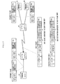
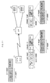
- Fig. 22 includes flowcharts according to a fourteenth embodiment of the present invention.
- Fig. 22(1) shows a procedure of an AP in a downlink
- Fig. 22(2) shows a procedure of a mobile terminal in an uplink
- Fig. 23 shows frame formats for the downlink and the uplink in the fourteenth embodiment.
- the AP searches an idle radio channel by carrier sense and acquires a number of simultaneous transmissions M (S651).
- a case is considered in which simultaneous transmission is performed using a plurality of radio channels.
- MIMO number or a number corresponding to a total number of MIMOs of a plurality of radio channels in the case where MIMO is used may be used as the number of simultaneous transmissions M.
- the AP acquires the number K of Ethernet frames that are the same in a destination address (an address of a mobile terminal) as the first Ethernet frame in the transmission buffer (S652). Then, the AP selects N (1 ⁇ N ⁇ K) Ethernet frames that are to be transmitted simultaneously from the K Ethernet frames within a range in which the selected Ethernet frames can be accommodated in M wireless packets (S653). The AP also acquires a source address SA from a header of each of the N Ethernet frames (S654). Then, the AP adds control information containing the source address SA of the corresponding Ethernet frame to a frame body (IP packet) of each of the N Ethernet frames, and connects the N frames bodies so as to generate a first block (S655).
- IP packet frame body
- the AP divides the first block into M so as to generate M blocks (S656).
- the AP generates M wireless packets that accommodate the M blocks as frame bodies, respectively, by adding a MAC header that contains a destination address DA, BSSID, and a source address SA, and FCS to each of the frame bodies.
- the AP transmits the M wireless packets simultaneously (S657).
- the frame body of the wireless packet is generated so as not to exceed the maximum data size that can be transmitted in one MAC frame (e.g., 2296 bytes).
- Fig. 23(1) shows an example in which an AP 10 converts three Ethernet frames respectively transmitted from servers 12 to 14 into two wireless packets and transmits those wireless packets simultaneously by using two radio channels.
- an Ethernet frame transmitted from the server 12 and a part of an Ethernet frame transmitted from the server 13 are aggregated to each other, and a remaining part of the Ethernet frame from the server 13 and an Ethernet frame from the server 14 are aggregated to each other.
- "S1" as the destination address DA, "AP" as BSSID, and a given address (e.g., AP) as the source address SA are set.
- the mobile terminal searches an idle radio channel by carrier sense and acquires the number of simultaneous transmissions M (S661). Then, the mobile terminal acquires the number K of IP packets in the transmission buffer that are sent to the same AP (S662). The mobile terminal selects N (1 ⁇ N ⁇ K) IP packets that are to be transmitted simultaneously from the K IP packets within a range in which the selected IP packets can be accommodated in M wireless packets (S663). The mobile terminal also acquires a destination address DA from an IP header of each of the N IP packets (S664). Then, the mobile terminal adds control information to each of the N IP packets.
- the control information contains the destination address DA of the corresponding IP packet.
- the mobile terminal then connects the N IP packets so as to generate a first block (S665) and thereafter generates M blocks by dividing the first block into M (S666). Then, the mobile terminal generates wireless packets by adding a MAC header and FCS to each of the M blocks serving as frame bodies of the wireless packets.
- the MAC header contains BSSID, a source address SA, and a destination address DA. The mobile terminal transmits those wireless packets simultaneously (S667).
- Fig. 23(2) shows an example in which a mobile terminal 11 generates wireless packets from IP packets to the servers 12 to 14 and transmits those wireless packets simultaneously by using two radio channels.
- an IP packet to the server 12 and a part of an IP packet to the server 13 are aggregated to each other, and a remaining part of the IP packet to the server 13 and an IP packet to the server 14 are aggregated to each other.
- "AP" as BSSID, "S1" as the source address SA, and a given address (e.g., AP) as the destination address DA are set.
- AP as BSSID
- S1 as the source address SA
- a given address e.g., AP
- the IP packets to the servers 12 to 14 are accommodated with the destination addresses DA thereof, while being fragmented, if necessary.
- Fig. 24 includes flowcharts according to a fifteenth embodiment of the present invention.
- Fig. 24(1) shows a procedure of an AP in a downlink
- Fig. 24(2) shows a procedure of a mobile terminal in an uplink
- Fig. 25 shows frame formats for the downlink and the uplink in the fifteenth embodiment.
- the AP searches an idle radio channel by carrier sense and acquires a number of simultaneous transmissions M (S671).
- a case is considered in which simultaneous transmission is performed using a plurality of radio channels.
- MIMO number or a number corresponding to a total number of MIMOs of a plurality of radio channels in the case where MIMO is used may be used as the number of simultaneous transmissions M.
- the AP acquires the number K of Ethernet frames that are the same in a destination address (an address of a mobile terminal) as the first Ethernet frame in the transmission buffer (S672).
- the AP selects N (1 ⁇ N ⁇ K) Ethernet frames for generating M wireless packets, by aggregating the K Ethernet frames in order within a range in which the selected Ethernet frames can be accommodated in the respective wireless packets (S673).
- the AP also acquires a source address SA from a header of each of the N Ethernet frames (S674).
- the AP adds control information containing the source address SA of the corresponding Ethernet frame to a frame body (IP packets) of each of the N Ethernet frames and aggregates the N frame bodies to one another, and generates M wireless packets in each of which a MAC header containing a destination address DA, BSSID, and a source address SA, and FCS are added.
- the AP then transmits the M wireless packets simultaneously (S675).
- the packet time lengths of the wireless packets are different, the packet time lengths of all the wireless packets are made the same by adding dummy data, if necessary.
- Fig. 25(1) shows an example in which an AP 10 converts three Ethernet frames respectively transmitted from servers 12 to 14 into two wireless packets and transmits those wireless packets simultaneously by using two radio channels.
- an Ethernet frame from the server 12 and an Ethernet frame from the server 13 are aggregated to each other, and an Ethernet frame from the server 14 is aggregated to dummy data.
- "S1" as the destination address DA, "AP" as BSSID, and a given address (e.g., AP) as the source address SA are set.
- the mobile terminal searches an idle radio channel by carrier sense and acquires the number of simultaneous transmissions M (S681). Then, the mobile terminal acquires the number K of IP packets in the transmission buffer that are sent to the same AP (S682).
- the mobile terminal selects N (1 ⁇ N ⁇ K) IP packets for generating M wireless packets by aggregating the K IP packets in order within a range in which the selected IP packets can be accommodated in the respective wireless packets (S683).
- the mobile terminal also acquires a destination address DA from an IP header of each of the N IP packets (S684).
- the mobile terminal generates wireless packets by adding control information containing the destination address DA of the corresponding IP packet to each of the N IP packets, aggregating the N IP packets, and further adding MAC headers each containing BSSID, a source address SA, and a destination address DA, and FCSs.
- the mobile terminal transmits those wireless packets simultaneously (S685).
- Fig. 25(2) shows an example in which a mobile terminal 11 generates wireless packets from IP packets to servers 12 to 14 and transmits those wireless packets simultaneously by using two radio channels.
- an IP packet to the server 12 and an IP packet to the server 13 are aggregated to each other, and an IP packet to the server 14 is aggregated to dummy data.
- "AP" as BSSID, "S1" as the source address SA, and a given address (e.g., AP) as the destination address DA are set.
- AP as BSSID
- S1 as the source address SA
- a given address e.g., AP
- the IP packets to the servers 12 to 14 are accommodated in order with the destination addresses DA thereof.
- Fig. 26 shows an exemplary frame format according to a sixteenth embodiment of the present invention.
- a wireless packet communication method corresponding to any of the twelfth to fifteenth embodiments is applied as a method for transferring wireless packets between STAs in a Multi-Hop Wireless Network.
- a frame aggregation method of the twelfth embodiment is applied.
- the thirteenth to fifteenth embodiments can be applied in a similar manner.
- Fig. 26 shows the case where an STA (S1) 21 and an STA (S2) 22 transmit wireless packets to an STA (S4) 24 via an STA (S3) 23.
- STA 23 selects two data frames respectively transmitted from the STAs 21 and 22 to the STA 24, adds addresses (S1 and S2) of the STAs 21 and 22 as source addresses SA to frame bodies of the two data frames, respectively, aggregates the frame bodies with the corresponding source addresses SA to each other, generates one wireless packet by adding a MAC header, and transmits the wireless packet in one lump.
- the transmission in the opposite direction can be carried out in a similar manner.
- the STA 24 adds addresses of the STAs 21 and 22 (S1 and S2) as destination addresses DA to frame bodies of the data frames, respectively, aggregates the frame bodies, generates one wireless packet by adding a MAC header, and transmits that wireless packet in one lump.
- Fig. 27 shows an exemplary frame format according to a seventeenth embodiment of the present invention.
- the wireless packet communication method corresponding to any of the twelfth to fifteenth embodiments is applied as a method for transferring wireless packets between STAs in a Wireless Bridge.
- the frame aggregation method of the twelfth embodiment is applied.
- the methods of the thirteenth to fifteenth embodiments can be applied in a similar manner.
- Fig. 27 shows the case where, when a terminal (S1) 31 and a terminal (S3) 32 transmit Ethernet frames to a terminal (S3) 33, an STA (AP1) 41 connected to the terminals 31 and 32 and an STA (AP2) 42 connected to the terminal 33 intervene.
- the STA 41 selects two Ethernet frames respectively transmitted from the terminals 31 and 32 to the terminal 33, adds addresses (S1 and S2) of the terminals 31 and 32 as source addresses SA to frame bodies of the two Ethernet frames, respectively, aggregates the frame bodies with the corresponding source addresses SA to each other, generates one wireless packet by adding a MAC header, and transmits the wireless packet in one lump.
- the transmission in the opposite direction can be carried out in a similar manner.
- the STA 42 When transferring Ethernet frames to the terminals 31 and 32 that are accumulated in the transmission buffer, to the STA 41, the STA 42 adds addresses (S1 and S2) of the terminals 31 and 32 as destination addresses DA to frame bodies of the selected Ethernet frames, respectively, aggregates the frame bodies with the destination addresses DA to each other, generates one wireless packet by adding a MAC header, and transmits that wireless packet in one lump.
- the present invention it is possible to easily generate a plurality of data packets having the same packet time length from transmission-standby data frames in a transmission buffer in accordance with the number of the transmission-standby data frames and the number of idle channels, while effectively using the maximum size of a data field that can be accommodated in a MAC packet.
- a plurality of radio channels are idle at the same time, the thus generated data packets can be transmitted simultaneously and the maximum throughput can be largely improved.
Landscapes
- Engineering & Computer Science (AREA)
- Computer Networks & Wireless Communication (AREA)
- Signal Processing (AREA)
- Mobile Radio Communication Systems (AREA)
- Time-Division Multiplex Systems (AREA)
- Data Exchanges In Wide-Area Networks (AREA)
- Small-Scale Networks (AREA)
- Communication Control (AREA)
Applications Claiming Priority (9)
| Application Number | Priority Date | Filing Date | Title |
|---|---|---|---|
| JP2003173953 | 2003-06-18 | ||
| JP2003173914 | 2003-06-18 | ||
| JP2003177096 | 2003-06-20 | ||
| JP2003177097 | 2003-06-20 | ||
| JP2003207699 | 2003-08-18 | ||
| JP2003349223 | 2003-10-08 | ||
| JP2004017247 | 2004-01-26 | ||
| JP2004158078 | 2004-05-27 | ||
| PCT/JP2004/008911 WO2004114609A1 (fr) | 2003-06-18 | 2004-06-18 | Procede de communication radio par paquets |
Publications (3)
| Publication Number | Publication Date |
|---|---|
| EP1635517A1 true EP1635517A1 (fr) | 2006-03-15 |
| EP1635517A4 EP1635517A4 (fr) | 2017-07-05 |
| EP1635517B1 EP1635517B1 (fr) | 2021-04-14 |
Family
ID=33545736
Family Applications (1)
| Application Number | Title | Priority Date | Filing Date |
|---|---|---|---|
| EP04746380.7A Expired - Lifetime EP1635517B1 (fr) | 2003-06-18 | 2004-06-18 | Procede de communication par paquets sans fil |
Country Status (6)
| Country | Link |
|---|---|
| US (2) | US7953115B2 (fr) |
| EP (1) | EP1635517B1 (fr) |
| JP (1) | JP3917638B2 (fr) |
| KR (1) | KR100807466B1 (fr) |
| CA (1) | CA2513345C (fr) |
| WO (1) | WO2004114609A1 (fr) |
Cited By (3)
| Publication number | Priority date | Publication date | Assignee | Title |
|---|---|---|---|---|
| US9036610B2 (en) | 2009-05-08 | 2015-05-19 | Sony Corporation | Communication apparatus, communication method, and communication system for handling frames of variable length |
| EP2187575A4 (fr) * | 2007-09-26 | 2016-10-19 | Nec Corp | Appareil de transmission, système de transmission, procédé de transmission et programme de transmission |
| US11184264B2 (en) | 2020-02-21 | 2021-11-23 | Rohde & Schwarz Gmbh & Co. Kg | Error rate test method and test system for testing a device under test |
Families Citing this family (44)
| Publication number | Priority date | Publication date | Assignee | Title |
|---|---|---|---|---|
| KR100764973B1 (ko) * | 2003-09-09 | 2007-10-08 | 니폰덴신뎅와 가부시키가이샤 | 무선 패킷 통신방법 및 무선 패킷 통신장치 |
| US8090857B2 (en) * | 2003-11-24 | 2012-01-03 | Qualcomm Atheros, Inc. | Medium access control layer that encapsulates data from a plurality of received data units into a plurality of independently transmittable blocks |
| KR100654449B1 (ko) * | 2005-02-01 | 2006-12-06 | 삼성전자주식회사 | 단일 무선 네트워크 인터페이스에서 다수의 무선 링크를통해 데이터를 송수신하는 장치 및 방법 |
| JP4632805B2 (ja) * | 2005-02-15 | 2011-02-16 | 三菱電機株式会社 | 複数経路マルチホップ無線lanシステム |
| US20070171933A1 (en) * | 2006-01-23 | 2007-07-26 | Interdigital Technology Corporation | Medium access control and physical layer headers for high throughput data in wlan systems |
| JP4566922B2 (ja) * | 2006-02-10 | 2010-10-20 | 日本電信電話株式会社 | 無線通信方法 |
| KR100728038B1 (ko) * | 2006-03-03 | 2007-06-14 | 삼성전자주식회사 | Plc 네트워크상에서 데이터를 묶어서 전송하는 방법 및장치 |
| JP4675825B2 (ja) * | 2006-05-19 | 2011-04-27 | 三菱電機株式会社 | データ転送方法 |
| CN100576822C (zh) | 2006-08-23 | 2009-12-30 | 上海贝尔阿尔卡特股份有限公司 | 无线通信网络中的数据传输及解析方法及其装置 |
| US8861597B2 (en) * | 2006-09-18 | 2014-10-14 | Sharp Laboratories Of America, Inc. | Distributed channel time allocation for video streaming over wireless networks |
| JP2007221817A (ja) * | 2007-03-27 | 2007-08-30 | Kyocera Corp | 無線基地局、チャネル割当システムおよびチャネル割当方法 |
| US8259871B2 (en) * | 2007-07-18 | 2012-09-04 | Panasonic Corporation | Reception device, transmission device, and adaptive transmission rate control method |
| KR101626152B1 (ko) * | 2007-11-20 | 2016-06-01 | 삼성전자주식회사 | 통신 시스템에서 데이터 재전송 시스템 및 방법 |
| JP4996451B2 (ja) | 2007-12-28 | 2012-08-08 | 株式会社東芝 | 無線通信装置、無線通信方法、及びプログラム |
| BRPI0823001A2 (pt) * | 2008-08-08 | 2015-07-28 | Fujitsu Ltd | Aparelho de comunicação, programa de geração de dados de transmissão e método de geração de dados de transmissão |
| US8464138B2 (en) * | 2008-08-20 | 2013-06-11 | Qualcomm Incorporated | Effective utilization of header space for error correction in aggregate frames |
| JP5010573B2 (ja) * | 2008-11-27 | 2012-08-29 | 株式会社東芝 | 無線装置およびその制御方法 |
| US8542706B2 (en) * | 2008-12-08 | 2013-09-24 | Qualcomm Incorporated | Method and apparatus related to packet fragmentation and reconstruction |
| WO2010070793A1 (fr) * | 2008-12-19 | 2010-06-24 | パナソニック株式会社 | Terminal émetteur et terminal récepteur |
| US10411846B1 (en) | 2009-03-24 | 2019-09-10 | Marvell International Ltd. | Multi-radio device for WLAN |
| US8773969B1 (en) | 2009-03-24 | 2014-07-08 | Marvell International Ltd. | Multi-radio device for WLAN |
| US9226270B1 (en) | 2009-03-24 | 2015-12-29 | Marvell International Ltd. | Multi-radio device for WLAN |
| JP5316208B2 (ja) | 2009-05-08 | 2013-10-16 | ソニー株式会社 | 通信装置及び通信方法、コンピューター・プログラム、並びに通信システム |
| US20100303096A1 (en) * | 2009-06-02 | 2010-12-02 | Assaf Kasher | Apparatus and mehtods for increased mac header protection |
| PL3285409T3 (pl) * | 2009-11-04 | 2024-12-09 | Electronics And Telecommunications Research Institute | Sposób i urządzenie do transmisji ramki danych w systemie komunikacji bezprzewodowej |
| KR101650573B1 (ko) * | 2009-11-27 | 2016-08-23 | 삼성전자주식회사 | 다중 사용자 ofdm 시스템의 적응적 자원 할당 방법 및 장치 |
| BR112012022751B1 (pt) | 2010-03-11 | 2021-09-14 | Electronics And Telecommunications Research Institute | Aparelho e método de comunicação sem fio |
| KR101655269B1 (ko) * | 2010-05-28 | 2016-09-07 | 삼성전자주식회사 | 무선통신시스템에서 자원분배 장치 및 방법 |
| US8989213B2 (en) | 2010-09-15 | 2015-03-24 | Qualcomm Incorporated | Physical layer header with access point identifier |
| US8619786B2 (en) | 2010-10-20 | 2013-12-31 | Qualcomm Incorporated | Facilitating distributed channel access for transmissions in a wireless communication environment |
| EP2661850B1 (fr) | 2011-01-06 | 2018-10-03 | Marvell World Trade Ltd. | Techniques de retard à décalage circulaire pour dispositifs radio multiples de réseau local sans fil |
| JP5218867B2 (ja) * | 2011-03-31 | 2013-06-26 | 横河電機株式会社 | プロビジョニングデバイス、およびプロビジョニングネットワークにおけるネットワークパラメータの設定方法 |
| JP5857661B2 (ja) * | 2011-11-18 | 2016-02-10 | 沖電気工業株式会社 | パケット処理装置及び方法 |
| US9014135B2 (en) * | 2012-01-03 | 2015-04-21 | Telefonaktiebolaget L M Ericsson (Publ) | Methods and apparatus for link adaptation for single user and multi-user MIMO |
| JP5744237B2 (ja) * | 2012-01-19 | 2015-07-08 | 三菱電機株式会社 | 多重ゲートウェイ装置、多重回線通信システム、多重回線通信方法およびプログラム |
| JP5522211B2 (ja) * | 2012-07-30 | 2014-06-18 | 富士通株式会社 | 通信装置、送信データ生成プログラム、および送信データ生成方法 |
| US9065483B2 (en) * | 2013-01-21 | 2015-06-23 | Micron Technology, Inc. | Determining soft data using a classification code |
| DE102013207826B3 (de) * | 2013-04-29 | 2014-07-17 | Ge Energy Power Conversion Gmbh | Verfahren zum Betreiben eines Slave-Knotens eines digitalen Bussystems |
| US9402199B2 (en) | 2013-10-14 | 2016-07-26 | Netgear, Inc. | Systems and methods for wireless load balancing and channel selection for a wireless device using WLAN modules operating simultaneously in different wireless bands |
| JP5888376B2 (ja) * | 2014-08-21 | 2016-03-22 | ソニー株式会社 | 通信装置及び通信方法、並びに通信システム |
| KR102291462B1 (ko) * | 2014-09-05 | 2021-08-18 | 삼성에스디에스 주식회사 | 정크 데이터 전송 채널 관리 방법, 정크 데이터 병렬적 전송 및 수신 방법 |
| US10270890B2 (en) * | 2015-07-13 | 2019-04-23 | Gainspan Corporation | Transmitting IP packets originating in a wireless station when the IP packets are destined for delivery to multiple destinations via an access point |
| JP6870994B2 (ja) * | 2017-01-23 | 2021-05-12 | キヤノンメディカルシステムズ株式会社 | X線コンピュータ断層撮影装置 |
| WO2018168701A1 (fr) * | 2017-03-14 | 2018-09-20 | 日本電気株式会社 | Dispositif de communication, système de communication, et procédé de communication |
Family Cites Families (22)
| Publication number | Priority date | Publication date | Assignee | Title |
|---|---|---|---|---|
| JP3209530B2 (ja) * | 1991-02-26 | 2001-09-17 | 富士通株式会社 | データ伝送装置 |
| JPH07111695B2 (ja) * | 1991-07-25 | 1995-11-29 | 株式会社メルコ | データ転送方法ならびにデータ送信装置および復元装置 |
| JP3462314B2 (ja) * | 1995-08-11 | 2003-11-05 | Kddi株式会社 | パケット通信装置 |
| JPH11154989A (ja) | 1997-11-19 | 1999-06-08 | Nec Mobile Commun Ltd | 装置間通信の負荷分散方式および負荷分散方法 |
| KR100457508B1 (ko) * | 1999-10-29 | 2004-11-17 | 삼성전자주식회사 | 타임 스탬프 옵셋 설정 장치 및 그 방법 |
| US6975666B2 (en) * | 1999-12-23 | 2005-12-13 | Institut National De La Recherche Scientifique | Interference suppression in CDMA systems |
| JP2002064459A (ja) * | 2000-08-16 | 2002-02-28 | Nippon Telegr & Teleph Corp <Ntt> | Ofdm送受信回路 |
| US7164669B2 (en) * | 2001-01-19 | 2007-01-16 | Adaptix, Inc. | Multi-carrier communication with time division multiplexing and carrier-selective loading |
| US6747993B2 (en) * | 2001-02-01 | 2004-06-08 | Motorola, Inc. | Method and apparatus for adjusting a communication timer in a communication network |
| US7116722B2 (en) * | 2001-02-09 | 2006-10-03 | Lucent Technologies Inc. | Wireless communication system using multi-element antenna having a space-time architecture |
| US7260115B1 (en) * | 2001-02-28 | 2007-08-21 | Symbol Technologies, Inc. | System and method of ordering the transmission of data packets in a radio system |
| EP1255369A1 (fr) * | 2001-05-04 | 2002-11-06 | TELEFONAKTIEBOLAGET LM ERICSSON (publ) | Adaptation de liaison pour des systèmes de communication sans fil à entrées multiples et sorties multiples |
| US7027523B2 (en) * | 2001-06-22 | 2006-04-11 | Qualcomm Incorporated | Method and apparatus for transmitting data in a time division duplexed (TDD) communication system |
| JP2003101604A (ja) * | 2001-09-20 | 2003-04-04 | Sony Corp | データ伝送方法及び装置並びにデータ受信方法及び装置 |
| US7248604B2 (en) * | 2001-10-30 | 2007-07-24 | Ipr Licensing, Inc. | Throughput in multi-rate wireless networks using variable-length packets and other techniques |
| US7630403B2 (en) * | 2002-03-08 | 2009-12-08 | Texas Instruments Incorporated | MAC aggregation frame with MSDU and fragment of MSDU |
| US7224704B2 (en) * | 2002-04-01 | 2007-05-29 | Texas Instruments Incorporated | Wireless network scheduling data frames including physical layer configuration |
| US6801580B2 (en) * | 2002-04-09 | 2004-10-05 | Qualcomm, Incorporated | Ordered successive interference cancellation receiver processing for multipath channels |
| US20040081131A1 (en) * | 2002-10-25 | 2004-04-29 | Walton Jay Rod | OFDM communication system with multiple OFDM symbol sizes |
| US7046651B2 (en) * | 2003-04-04 | 2006-05-16 | Nokia Corporation | System topologies for optimum capacity transmission over wireless local area networks |
| US20050051433A1 (en) * | 2003-04-23 | 2005-03-10 | Zdunek Alan D. | Method and apparatus for monitoring, dosing and distribution of chemical solutions |
| US7532600B2 (en) * | 2003-04-25 | 2009-05-12 | Alcatel-Lucent Usa Inc. | Method and system for using hybrid ARQ in communication systems that use multiple input multiple output antenna systems |
-
2004
- 2004-06-18 CA CA2513345A patent/CA2513345C/fr not_active Expired - Lifetime
- 2004-06-18 WO PCT/JP2004/008911 patent/WO2004114609A1/fr not_active Ceased
- 2004-06-18 US US10/542,209 patent/US7953115B2/en active Active
- 2004-06-18 EP EP04746380.7A patent/EP1635517B1/fr not_active Expired - Lifetime
- 2004-06-18 KR KR20057014988A patent/KR100807466B1/ko not_active Expired - Lifetime
- 2004-06-18 JP JP2005507284A patent/JP3917638B2/ja not_active Expired - Fee Related
-
2011
- 2011-04-18 US US13/088,801 patent/US8989219B2/en active Active
Non-Patent Citations (1)
| Title |
|---|
| See references of WO2004114609A1 * |
Cited By (6)
| Publication number | Priority date | Publication date | Assignee | Title |
|---|---|---|---|---|
| EP2187575A4 (fr) * | 2007-09-26 | 2016-10-19 | Nec Corp | Appareil de transmission, système de transmission, procédé de transmission et programme de transmission |
| US9036610B2 (en) | 2009-05-08 | 2015-05-19 | Sony Corporation | Communication apparatus, communication method, and communication system for handling frames of variable length |
| US9706436B2 (en) | 2009-05-08 | 2017-07-11 | Sony Corporation | Communication apparatus, communication method, and communication system for handling frames of variable length |
| US10111134B2 (en) | 2009-05-08 | 2018-10-23 | Sony Corporation | Communication apparatus, communication method, and communication system for handling frames of variable length |
| US10575214B2 (en) | 2009-05-08 | 2020-02-25 | Sony Corporation | Communication apparatus, communication method, and communication system for handling frames of variable length |
| US11184264B2 (en) | 2020-02-21 | 2021-11-23 | Rohde & Schwarz Gmbh & Co. Kg | Error rate test method and test system for testing a device under test |
Also Published As
| Publication number | Publication date |
|---|---|
| KR100807466B1 (ko) | 2008-02-25 |
| US7953115B2 (en) | 2011-05-31 |
| WO2004114609A1 (fr) | 2004-12-29 |
| JPWO2004114609A1 (ja) | 2006-07-27 |
| EP1635517A4 (fr) | 2017-07-05 |
| CA2513345A1 (fr) | 2004-12-29 |
| US20110194517A1 (en) | 2011-08-11 |
| JP3917638B2 (ja) | 2007-05-23 |
| US8989219B2 (en) | 2015-03-24 |
| CA2513345C (fr) | 2010-08-10 |
| EP1635517B1 (fr) | 2021-04-14 |
| KR20060016743A (ko) | 2006-02-22 |
| US20060139201A1 (en) | 2006-06-29 |
Similar Documents
| Publication | Publication Date | Title |
|---|---|---|
| CA2513345C (fr) | Methode et dispositif de communication de donnees par paquets sans fil | |
| US7668143B2 (en) | Wireless packet communication method and apparatus | |
| US9131398B2 (en) | Long range WLAN data unit format | |
| US9300767B2 (en) | MAC header compression in long-range wireless local area networks | |
| EP1626520A1 (fr) | Procédé et appareil pour transmettre des trames d'accusé de réception | |
| JP4045286B2 (ja) | 無線パケット通信方法および無線パケット通信装置 | |
| US20100046540A1 (en) | Communication apparatus and communication method | |
| US20060034274A1 (en) | System and method for variable length acknowledgements in a shared resource network | |
| EP1667364A1 (fr) | Procede et appareil de communication de paquets radio | |
| CN100473226C (zh) | 无线分组通信方法及无线分组通信装置 | |
| CN100542131C (zh) | 无线分组通信方法以及无线分组通信装置 | |
| US20050070270A1 (en) | Wireless communication apparatus | |
| US7370113B2 (en) | Wireless LAN apparatus |
Legal Events
| Date | Code | Title | Description |
|---|---|---|---|
| PUAI | Public reference made under article 153(3) epc to a published international application that has entered the european phase |
Free format text: ORIGINAL CODE: 0009012 |
|
| 17P | Request for examination filed |
Effective date: 20050714 |
|
| AK | Designated contracting states |
Kind code of ref document: A1 Designated state(s): DE FR GB |
|
| DAX | Request for extension of the european patent (deleted) | ||
| RBV | Designated contracting states (corrected) |
Designated state(s): DE FR GB |
|
| REG | Reference to a national code |
Ref country code: DE Ref legal event code: R079 Ref document number: 602004054950 Country of ref document: DE Free format text: PREVIOUS MAIN CLASS: H04L0012560000 Ipc: H04W0072040000 |
|
| RA4 | Supplementary search report drawn up and despatched (corrected) |
Effective date: 20170608 |
|
| RIC1 | Information provided on ipc code assigned before grant |
Ipc: H04W 72/04 20090101AFI20170601BHEP |
|
| STAA | Information on the status of an ep patent application or granted ep patent |
Free format text: STATUS: EXAMINATION IS IN PROGRESS |
|
| 17Q | First examination report despatched |
Effective date: 20170922 |
|
| GRAP | Despatch of communication of intention to grant a patent |
Free format text: ORIGINAL CODE: EPIDOSNIGR1 |
|
| STAA | Information on the status of an ep patent application or granted ep patent |
Free format text: STATUS: GRANT OF PATENT IS INTENDED |
|
| INTG | Intention to grant announced |
Effective date: 20201112 |
|
| GRAS | Grant fee paid |
Free format text: ORIGINAL CODE: EPIDOSNIGR3 |
|
| GRAA | (expected) grant |
Free format text: ORIGINAL CODE: 0009210 |
|
| STAA | Information on the status of an ep patent application or granted ep patent |
Free format text: STATUS: THE PATENT HAS BEEN GRANTED |
|
| REG | Reference to a national code |
Ref country code: DE Ref legal event code: R081 Ref document number: 602004054950 Country of ref document: DE Owner name: NIPPON TELEGRAPH AND TELEPHONE CORPORATION, JP Free format text: FORMER OWNER: NIPPON TELEGRAPH & TELEPHONE CO., TOKIO/TOKYO, JP |
|
| AK | Designated contracting states |
Kind code of ref document: B1 Designated state(s): DE FR GB |
|
| REG | Reference to a national code |
Ref country code: GB Ref legal event code: FG4D |
|
| REG | Reference to a national code |
Ref country code: DE Ref legal event code: R096 Ref document number: 602004054950 Country of ref document: DE |
|
| REG | Reference to a national code |
Ref country code: DE Ref legal event code: R097 Ref document number: 602004054950 Country of ref document: DE |
|
| PLBE | No opposition filed within time limit |
Free format text: ORIGINAL CODE: 0009261 |
|
| STAA | Information on the status of an ep patent application or granted ep patent |
Free format text: STATUS: NO OPPOSITION FILED WITHIN TIME LIMIT |
|
| 26N | No opposition filed |
Effective date: 20220117 |
|
| PGFP | Annual fee paid to national office [announced via postgrant information from national office to epo] |
Ref country code: FR Payment date: 20230622 Year of fee payment: 20 Ref country code: DE Payment date: 20230620 Year of fee payment: 20 |
|
| PGFP | Annual fee paid to national office [announced via postgrant information from national office to epo] |
Ref country code: GB Payment date: 20230620 Year of fee payment: 20 |
|
| REG | Reference to a national code |
Ref country code: DE Ref legal event code: R071 Ref document number: 602004054950 Country of ref document: DE |
|
| PG25 | Lapsed in a contracting state [announced via postgrant information from national office to epo] |
Ref country code: GB Free format text: LAPSE BECAUSE OF EXPIRATION OF PROTECTION Effective date: 20240617 |
|
| PG25 | Lapsed in a contracting state [announced via postgrant information from national office to epo] |
Ref country code: GB Free format text: LAPSE BECAUSE OF EXPIRATION OF PROTECTION Effective date: 20240617 |