EP1635989B2 - Improvements in and relating to the grinding of cylindrical surfaces and adjoining side-walls - Google Patents
Improvements in and relating to the grinding of cylindrical surfaces and adjoining side-walls Download PDFInfo
- Publication number
- EP1635989B2 EP1635989B2 EP05740437.8A EP05740437A EP1635989B2 EP 1635989 B2 EP1635989 B2 EP 1635989B2 EP 05740437 A EP05740437 A EP 05740437A EP 1635989 B2 EP1635989 B2 EP 1635989B2
- Authority
- EP
- European Patent Office
- Prior art keywords
- wheel
- grind
- plunge
- grinding
- cylindrical surface
- Prior art date
- Legal status (The legal status is an assumption and is not a legal conclusion. Google has not performed a legal analysis and makes no representation as to the accuracy of the status listed.)
- Expired - Lifetime
Links
Images




Classifications
-
- B—PERFORMING OPERATIONS; TRANSPORTING
- B24—GRINDING; POLISHING
- B24B—MACHINES, DEVICES, OR PROCESSES FOR GRINDING OR POLISHING; DRESSING OR CONDITIONING OF ABRADING SURFACES; FEEDING OF GRINDING, POLISHING, OR LAPPING AGENTS
- B24B5/00—Machines or devices designed for grinding surfaces of revolution on work, including those which also grind adjacent plane surfaces; Accessories therefor
- B24B5/36—Single-purpose machines or devices
- B24B5/42—Single-purpose machines or devices for grinding crankshafts or crankpins
-
- B—PERFORMING OPERATIONS; TRANSPORTING
- B24—GRINDING; POLISHING
- B24B—MACHINES, DEVICES, OR PROCESSES FOR GRINDING OR POLISHING; DRESSING OR CONDITIONING OF ABRADING SURFACES; FEEDING OF GRINDING, POLISHING, OR LAPPING AGENTS
- B24B27/00—Other grinding machines or devices
- B24B27/0076—Other grinding machines or devices grinding machines comprising two or more grinding tools
Definitions
- This invention concerns grinding methods and grinding machines particularly for grinding the main cylindrical bearing support surfaces and their adjacent sidewalls and the off-axis cylindrical crankpins and their adjacent sidewalls, of a crankshaft.
- EP-A-990483 discloses a grinding machine for grinding a crankshaft using two grinding wheels. Pin portions of the crankshaft are ground by moving the wheels along axes perpendicular to the rotational axis of the crankshaft.
- a plunge grinding method is described in US patent 4,603,514 (Toyoda ). This method involves a sequence of plunge grinds in which during at least some of the plunge grinds the relative movement between grinding wheel and workpiece is such that if the workpiece is considered to be stationary the wheel will be seen to move along a trajectory that is at an acute angle to the axis of the cylindrical surface it is to grind, and during grinding the wheel removes metal from both the cylindrical surface and an adjoining sidewall.
- the present invention is directed at a method of operating a grinding machine including a grinding wheel to grind a cylindrical surface on a workpiece, the cylindrical surface being bounded at one or both ends with a radial flange or sidewall which also has to be ground to size.
- the method comprises the steps of:-
- the stand-off may be achieved by axially displacing the wheel relative to the workpiece or the workpiece relative to the grinding wheel by a small distance.
- the relative axial movement may be stopped and the movement reversed for a small distance to create the stand-off so that thereafter the trajectory of the wheel is normal to the cylindrical surface to be ground.
- the wheel may be advanced along an angled path similar to that employed during the previous part of the grind, the stand-off preventing contact with, and metal removal from, the sidewall during the final angled approach of the wheel to complete the grind.
- the workspeed is reduced from the speed at which it is rotated during the previous part of the plunge to assist in achieving a desired grinding quality of the cylindrical region.
- the coolant flow rate is reduced from that which is employed during the previous part of the plunge, so as to achieve a desired grind quality of the cylindrical region.
- the method is applicable to grinding the cylindrical crank-pins or the main bearing support surfaces of a crankshaft, but can be employed when grinding any cylindrical surface bounded at one or both ends with a radial flange which also has to be ground to size.
- a diameter and two sidewalls are ground using a succession of two angled plunge grinds albeit with the side face of the grinding wheel stood off from the sidewall of the workpiece during a final part of each plunge grind.
- feed rate, dwells, workspeed, coolant pressure and flow rate are controlled in relation to end-points of the grind, so that a sidewall at one end of the cylindrical surface and the adjacent part of the latter are ground to size in the manner hereinbefore described.
- the wheel After grinding the sidewall and diameter by the first plunge grind at one end, the wheel is retracted and if necessary indexed laterally before a second angled plunge grind is performed this time moving the wheel along a trajectory towards the sidewall at the other end of the cylindrical surface, thereby to grind the sidewall and diameter at the other end of the cylindrical surface.
- the lateral indexing is not more than 2/3 of the wheel width so as to ensure overlap on the diameter between plunges.
- one or more perpendicular plunge grinds may be performed between the first and second angled plunge grinds or after the second angled plunge grind.
- the process employs a dressed profiled wheel.
- the wheel can have an equal depth of CBN grit on each of the two side faces, and by selecting an appropriate depth of CBN grit around the cylindrical face of the wheel, the wheel should wear uniformly in use so that all of the CBN grit around the wheel should be utilised before the wheel has to be replaced.
- the thickness of the CBN layers can be as follows:
- the invention is also directed at a grinding machine and programmable computer based control system therefor according to claim 23.
- a two-wheel grinding machine may be employed, each wheel being controlled to perform an angled grind with lateral stand-off thereafter, prior to the final part of each grind provided the two wheels are independently controllable along the X and Z axes of the machine.
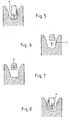
- FIG. 1-14 A method embodying the invention and part of apparatus for performing the method is shown in the accompanying Figs 1-14 .
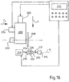
- FIG 15 A typical computer controlled grinding machine is shown in Fig 15 , a diagrammatic illustration of the external parts of the grinding machine is shown in Fig 16 and the computer program steps involved in operating the machine to perform the sidewall grind in accordance with the diagonal grinding proposed by the invention, is shown in Fig 17 .
- Fig 1 the wheelhead is moved axially relative to the crankshaft 4 in the direction marked "A" so as to be positioned adjacent the region to be ground for first plunge grind. This is referred to as the lateral start position of the wheel 2.
- Fig 2 the wheel 2 is shown after a rapid plunge move in the direction marked "B" to an end point in which the wheel is at an equal distance from the sidewall 6 and cylindrical region 8 to be ground.
- Fig 3 the wheel is shown during an angled plunge to the right in the direction marked "C” using programmable feeds in the directions of the RH sidewall 6 and the cylindrical region 8, to programmable end points.
- Ideal angle of feed is 45° with the sidewall end point 6' being reached before that of the central region diameter 8' by a distance "x" of approximately 0.010mm.
- Other functions controlled during the plunge by means of staggered control end points are dwells, multi-stage feedrates, coolant pressure control and workspeeds, to gain a desired grind quality.
- the part rotation speed is typically 80RPM (journal) or 40RPM (pin).
- Fig 4 the wheel is shown in the stand-off position (after movement in the direction marked "D") required before the remainder of the right hand plunge grind is performed.
- the stand-off positions the wheel a distance of "y" 0.050mm clear of the sidewall.
- the workspeed and coolant flow rate are reduced and the wheel continues to advance perpendicularly to the axis of the cylindrical region.
- the workpiece is rotated at 20RPM.
- Fig 5 the wheel is shown at the end point of the final part of the plunge after movement in the direction marked "E", during which the sequence continues to use the staggered control end points, controlling dwells, multistage feedrates, coolant pressure control and workspeeds, to ensure the desired grind quality for the cylindrical surface.
- Fig 6 the wheel is shown retracted in direction "F" clear of the workpiece to a programmable safe position from the wheelhead to allow lateral indexing of the wheelhead towards the LH end of the region being ground.
- Fig 7 the wheel is shown after lateral indexing in direction "G" to an initial position for the second angled plunge grind.
- Fig 8 the wheel is shown after a rapid plunge movement in direction "H" to the end point from which the LH angled plunge grind is to begin. This corresponds to the start position of Fig 2 for the RH angled plunge.
- Fig 9 the wheel is shown during the angled LH plunge grind during which programmable feeds in the directions of the LH sidewall and central region diameter are used, to move the wheel in direction "I" to programmable end points.
- the ideal angle of feed is 45°, with the LH sidewall end point being reached before that of the central region diameter by approximately 0.010mm.
- other functions controlled during the plunge by means of staggered control end points are dwells, multi-stage feedrates, coolant pressure control and workspeeds, to gain the desired grind quality.
- the part rotation speed is 80RPM (journal) or 40RPM (pin).
- Fig 10 shows the wheel in its second stand-off position - in which the wheel is once again stood off in direction "J" by 0.050mm (distance “z") this time from the LH sidewall, and the workspeed and coolant flow rate are reduced.
- the speed of rotation may be reduced to 20RPM, typically. If the axial movement of the workpiece is arrested during the final part of the grind, the grinding trajectory will be perpendicular to the axis of the cylindrical region, instead of at 45°.
- Fig 11 the wheel is shown at the end point of the final part of the plunge in direction "K", during which the sequence continues to use the staggered control end points, controlling dwells, multi-stage feedrates, coolant pressure control and workspeeds, to ensure the desired grind quality for the cylindrical surface.
- Fig 12 the wheel is shown retracted clear of the workpiece in direction "L" to a programmable safe position ready for subsequent lateral indexing of the wheelhead relative to that region of the workpiece if a further plunge grind is required, (typically without simultaneous axial movement of the workpiece) should the width of the wheel be insufficient for the whole of the axial length of the cylindrical region to have been ground to final diameter.
- Fig 13 the wheel 2 is shown further retracted so that the wheelhead can index to the next part of the crankshaft 4 which is to be ground, and the multiple plunge grind sequence is repeated from Fig 1 above.
- Fig 14 shows a crankshaft workpiece 4 mounted between headstock 10 and tailstock 12 with the wheelhead 14 ready to advance to the first grinding position, but parked in a position clear of the workpiece to allow the latter to be demounted or mounted.
- Fig 15 shows a grinding machine 68.
- the machine shown includes two grinding wheels 70,72 driven by motors 74,76 and mounted on wheelheads 78,80 for separate and simultaneous movement towards and away from a workpiece 82 along linear tracks 84,86 under the control of wheelfeed drive motors 88,90.
- the workpiece is mounted between centres in a tailstock 92 and a headstock 94 which also houses a motor (not shown) for rotating the workpiece 82 via a chuck 96.
- the workpiece shown is a crankshaft of an internal combustion engine and includes offset crankpins such 98 which are to be ground to size, each of which constitutes a cylindrical workpiece for grinding.
- a computer 100 running a suitable programme controls the operation of the machine and inter alia moves the wheelhead 78 (or both wheelheads 78,80) towards and away from the workpiece 82 as the workpiece rotates, so as to maintain contact between the wheel and the crankpin being ground, as the latter rotates circularly around the axis of the workpiece centres.
- a gauge may be carried by the wheelhead assembly for in-process gauging the diameter of the crankpin as it is ground.
- At 102 is mounted a hydraulically or pneumatically operated worksteady having a base 104 and movable cantilever arm 106 adapted at the right hand end as shown to engage a cylindrical journal bearing region of the crankshaft workpiece 82.
- Controlling signals for advancing and retracting 106 are derived from the computer 100.
- Wheel diameter sensing gauges may be included, signals from which are supplied back to the computer 100.
- the wheelhead 78 is movable along an axis parallel to the workpiece axis (the Z axis) by a further drive.
- a wheelhead 200 having a wheel drive motor 202, a Z-axis feed drive motor 204 and an X-axis feed drive motor 206.
- the X and Z axes are denoted by labelled arrows.
- a grinding wheel 208 is mounted to one side of the wheelhead 200 and movement of the wheelhead is controlled by signals from a computer based control system 210.
- a workpiece 212 is shown mounted between headstock 214 and tailstock 216.
- the former includes a C-axis drive motor (not shown) for rotating the workpiece about its lengthwise axis.
- the workpiece includes radial flanges at 218, 220 between a cylindrical region 222 and the purpose of the grind is to finish grind the opposed sidewalls denoted by 224, 226 and the diameter of the cylindrical region 222.
- the wheelhead is moved relative to the workpiece so that one sidewall of the grinding wheel is brought into grinding contact with one of the two sidewalls (for example 224) of the workpiece, the feed movement of the wheelhead being controlled along both X and Z axes, so that the wheel and wheelhead describe a trajectory which makes an acute angle with the workpiece axis - typically 45°, until the sidewall grind is complete, after which the wheel is stood off from the sidewall 224 and the wheelhead is advanced so as to finish the grind the diameter of region 222, whilst maintaining the stand off between the sidewall of wheel and the sidewall of workpiece 224.
- the other workpiece sidewall 226 is then ground using the other sidewall of the grinding wheel, and the remainder of the cylindrical region 222 is ground, whilst the wheel is stood off from the second workpiece sidewall 226.
- Fig 17 shows the steps required to be performed by the computer 210 in response to feedback from gauges and or X and Z axis position signals.
- step 228 causes wheel feed 206 to move the wheelhead 200 parallel to the X-axis.
- the X-feed 206 is controlled so that a specific diameter of the region 222 will be ground.
- step 230 produces a YES signal to initiate a sidewall grind.
- the first sidewall to be ground is 226 of Fig 16 .
- Step 282 of the programme causes Z-axis movement towards the chosen sidewall (226 in the example under consideration) which is simultaneous with the X-axis movement initiated by step 228.
- Step 232 provides two outputs one to a Z-axis drive controlling step 234 and one to a monitoring logic step 236 which determines whether the X-axis feed has achieved the desired diameter of the region 222.
- step 238 which produces a YES signal when the combined X and Z axes movement has resulted in the sidewall 226 having been ground to size (measured in the Z direction).
- a YES signal from step 238 triggers step 240 to instigate a reverse Z-axis motion to back off the sidewall of the wheel 208 from contact with the sidewall 216, now ground to size.
- An output signal from 240 indicates back off is completed.
- a logic stage 242 provides a YES signal if the output signal from 240 indicates back off is complete and the X-axis movement has achieved the desired position in region 222.
- a similar logic stage 244 provides a YES signal if the sidewall cycle including back-off is complete when the monitoring step 235 confirms that the region 222 has been ground to size.
- step 246 reverses the X-feed drive 206 to retract the wheel.
Landscapes
- Engineering & Computer Science (AREA)
- Mechanical Engineering (AREA)
- Grinding Of Cylindrical And Plane Surfaces (AREA)
- Constituent Portions Of Griding Lathes, Driving, Sensing And Control (AREA)
- Polishing Bodies And Polishing Tools (AREA)
- Shafts, Cranks, Connecting Bars, And Related Bearings (AREA)
Priority Applications (1)
| Application Number | Priority Date | Filing Date | Title |
|---|---|---|---|
| DE602005002993.1T DE602005002993T3 (de) | 2004-05-15 | 2005-05-06 | Verbesserungen betreffend das schleifen von zylindrischen flächen und daran angrenzenden seitenflächen |
Applications Claiming Priority (3)
| Application Number | Priority Date | Filing Date | Title |
|---|---|---|---|
| GBGB0410944.3A GB0410944D0 (en) | 2004-05-15 | 2004-05-15 | Improvements in and relating to the grinding of cylindrical surfaces and adjoining side-walls |
| GB0413783A GB2413978B (en) | 2004-05-15 | 2004-06-21 | Improvements in and relating to the grinding of cylindrical surfaces and adjoining side-walls |
| PCT/GB2005/001727 WO2005110676A1 (en) | 2004-05-15 | 2005-05-06 | Improvements in and relating to the grinding of cylindrical surfaces and adjoining side-walls |
Publications (3)
| Publication Number | Publication Date |
|---|---|
| EP1635989A1 EP1635989A1 (en) | 2006-03-22 |
| EP1635989B1 EP1635989B1 (en) | 2007-10-24 |
| EP1635989B2 true EP1635989B2 (en) | 2019-12-25 |
Family
ID=34967009
Family Applications (1)
| Application Number | Title | Priority Date | Filing Date |
|---|---|---|---|
| EP05740437.8A Expired - Lifetime EP1635989B2 (en) | 2004-05-15 | 2005-05-06 | Improvements in and relating to the grinding of cylindrical surfaces and adjoining side-walls |
Country Status (5)
| Country | Link |
|---|---|
| EP (1) | EP1635989B2 (es) |
| AT (1) | ATE376474T1 (es) |
| DE (1) | DE602005002993T3 (es) |
| ES (1) | ES2293575T5 (es) |
| WO (1) | WO2005110676A1 (es) |
Families Citing this family (4)
| Publication number | Priority date | Publication date | Assignee | Title |
|---|---|---|---|---|
| DE102010026026B4 (de) * | 2010-07-03 | 2019-01-03 | Emag Holding Gmbh | Verfahren und Schleifmaschine zum Schleifen von Rotationsflächen |
| DE102014204807B4 (de) | 2014-03-14 | 2016-12-15 | Erwin Junker Grinding Technology A.S. | Verfahren und Vorrichtung zum Schleifen von Großkurbelwellen |
| EP3115149B1 (en) | 2015-07-08 | 2018-03-14 | Scania CV AB | Method of grinding a workpiece having a cylindrical bearing surface and method for determining processing parameters |
| CN116619178A (zh) * | 2023-05-31 | 2023-08-22 | 银川隆基光伏科技有限公司 | 硅棒磨弧方法及其装置、硅片制造方法及电池片制造方法 |
Family Cites Families (4)
| Publication number | Priority date | Publication date | Assignee | Title |
|---|---|---|---|---|
| JPS60114454A (ja) * | 1983-11-19 | 1985-06-20 | Toyoda Mach Works Ltd | クランク軸の研削方法 |
| JPH0890408A (ja) * | 1994-09-27 | 1996-04-09 | Toyoda Mach Works Ltd | 研削方法 |
| JP2000107901A (ja) * | 1998-09-29 | 2000-04-18 | Toyoda Mach Works Ltd | クランクシャフトの加工方法 |
| JP2002307268A (ja) * | 2001-04-19 | 2002-10-23 | Toyoda Mach Works Ltd | 測定装置を用いた工作物の偏心円筒部の加工方法及び加工装置 |
-
2005
- 2005-05-06 AT AT05740437T patent/ATE376474T1/de not_active IP Right Cessation
- 2005-05-06 WO PCT/GB2005/001727 patent/WO2005110676A1/en not_active Ceased
- 2005-05-06 DE DE602005002993.1T patent/DE602005002993T3/de not_active Expired - Lifetime
- 2005-05-06 ES ES05740437T patent/ES2293575T5/es not_active Expired - Lifetime
- 2005-05-06 EP EP05740437.8A patent/EP1635989B2/en not_active Expired - Lifetime
Also Published As
| Publication number | Publication date |
|---|---|
| EP1635989A1 (en) | 2006-03-22 |
| ES2293575T5 (es) | 2020-07-23 |
| WO2005110676A1 (en) | 2005-11-24 |
| EP1635989B1 (en) | 2007-10-24 |
| DE602005002993T2 (de) | 2008-08-14 |
| ES2293575T3 (es) | 2008-03-16 |
| ATE376474T1 (de) | 2007-11-15 |
| DE602005002993T3 (de) | 2020-04-09 |
| DE602005002993D1 (de) | 2007-12-06 |
Similar Documents
| Publication | Publication Date | Title |
|---|---|---|
| CN102264510B (zh) | 内齿轮磨削机和用于桶状螺纹刀具的修整方法 | |
| US6319097B1 (en) | Grinding methods and apparatus | |
| CN102264511B (zh) | 内齿轮磨削机 | |
| EP1224057A1 (en) | Crankpin grinding method | |
| JPH07100761A (ja) | 研削装置 | |
| KR20170129825A (ko) | 그루브가 있는 워크피스를 연삭하기 위한 방법 및 연삭 머신 | |
| EP1839809B1 (en) | Grinding method and grinding machine | |
| JP5383556B2 (ja) | 歯車研削用砥石のツルーイング方法及び歯車研削盤 | |
| EP1635989B2 (en) | Improvements in and relating to the grinding of cylindrical surfaces and adjoining side-walls | |
| US6893324B1 (en) | Angle head grinding apparatus | |
| GB2413978A (en) | Angled plunge grinding of cylindrical surfaces | |
| JP2008307633A (ja) | 工作物の研削方法 | |
| JPH1094920A (ja) | インボリュート歯形の加工方法 | |
| US3977126A (en) | Grinding machine | |
| JP3907977B2 (ja) | クランクシャフトの研削方法及び研削装置 | |
| JP3812869B2 (ja) | 円筒研削方法及び装置 | |
| JP5262437B2 (ja) | 砥石のツルーイング方法および研削加工方法 | |
| JP4482632B2 (ja) | 端面スラスト研削の多段送り研削加工方法 | |
| JP2542084B2 (ja) | 研削砥石の研削面修正方法 | |
| JP4699022B2 (ja) | ホーニング加工方法 | |
| JPS62282852A (ja) | 研削加工方法 | |
| JPH06134668A (ja) | 研削盤 | |
| JP2000176834A (ja) | 研削砥石の修正方法、並びに修正装置及びこれを備えた研削盤 | |
| JP2002283235A (ja) | 端面研削用砥石車のツルーイング方法 | |
| JPS63105887A (ja) | 心なし研削盤のドレス方法及び心なし研削盤 |
Legal Events
| Date | Code | Title | Description |
|---|---|---|---|
| PUAI | Public reference made under article 153(3) epc to a published international application that has entered the european phase |
Free format text: ORIGINAL CODE: 0009012 |
|
| 17P | Request for examination filed |
Effective date: 20051220 |
|
| AK | Designated contracting states |
Kind code of ref document: A1 Designated state(s): AT BE BG CH CY CZ DE DK EE ES FI FR GB GR HU IE IS IT LI LT LU MC NL PL PT RO SE SI SK TR |
|
| AX | Request for extension of the european patent |
Extension state: AL BA HR LV MK YU |
|
| RAP1 | Party data changed (applicant data changed or rights of an application transferred) |
Owner name: CINETIC LANDIS GRINDING LIMITED |
|
| 17Q | First examination report despatched |
Effective date: 20060929 |
|
| GRAP | Despatch of communication of intention to grant a patent |
Free format text: ORIGINAL CODE: EPIDOSNIGR1 |
|
| DAX | Request for extension of the european patent (deleted) | ||
| GRAS | Grant fee paid |
Free format text: ORIGINAL CODE: EPIDOSNIGR3 |
|
| GRAA | (expected) grant |
Free format text: ORIGINAL CODE: 0009210 |
|
| AK | Designated contracting states |
Kind code of ref document: B1 Designated state(s): AT BE BG CH CY CZ DE DK EE ES FI FR GB GR HU IE IS IT LI LT LU MC NL PL PT RO SE SI SK TR |
|
| REG | Reference to a national code |
Ref country code: GB Ref legal event code: FG4D |
|
| REG | Reference to a national code |
Ref country code: CH Ref legal event code: EP |
|
| REG | Reference to a national code |
Ref country code: IE Ref legal event code: FG4D |
|
| REF | Corresponds to: |
Ref document number: 602005002993 Country of ref document: DE Date of ref document: 20071206 Kind code of ref document: P |
|
| REG | Reference to a national code |
Ref country code: ES Ref legal event code: FG2A Ref document number: 2293575 Country of ref document: ES Kind code of ref document: T3 |
|
| NLV1 | Nl: lapsed or annulled due to failure to fulfill the requirements of art. 29p and 29m of the patents act | ||
| PG25 | Lapsed in a contracting state [announced via postgrant information from national office to epo] |
Ref country code: CH Free format text: LAPSE BECAUSE OF FAILURE TO SUBMIT A TRANSLATION OF THE DESCRIPTION OR TO PAY THE FEE WITHIN THE PRESCRIBED TIME-LIMIT Effective date: 20071024 Ref country code: SE Free format text: LAPSE BECAUSE OF FAILURE TO SUBMIT A TRANSLATION OF THE DESCRIPTION OR TO PAY THE FEE WITHIN THE PRESCRIBED TIME-LIMIT Effective date: 20080124 Ref country code: NL Free format text: LAPSE BECAUSE OF FAILURE TO SUBMIT A TRANSLATION OF THE DESCRIPTION OR TO PAY THE FEE WITHIN THE PRESCRIBED TIME-LIMIT Effective date: 20071024 Ref country code: LI Free format text: LAPSE BECAUSE OF FAILURE TO SUBMIT A TRANSLATION OF THE DESCRIPTION OR TO PAY THE FEE WITHIN THE PRESCRIBED TIME-LIMIT Effective date: 20071024 |
|
| REG | Reference to a national code |
Ref country code: CH Ref legal event code: PL |
|
| PG25 | Lapsed in a contracting state [announced via postgrant information from national office to epo] |
Ref country code: SI Free format text: LAPSE BECAUSE OF FAILURE TO SUBMIT A TRANSLATION OF THE DESCRIPTION OR TO PAY THE FEE WITHIN THE PRESCRIBED TIME-LIMIT Effective date: 20071024 Ref country code: BG Free format text: LAPSE BECAUSE OF FAILURE TO SUBMIT A TRANSLATION OF THE DESCRIPTION OR TO PAY THE FEE WITHIN THE PRESCRIBED TIME-LIMIT Effective date: 20080124 Ref country code: IS Free format text: LAPSE BECAUSE OF FAILURE TO SUBMIT A TRANSLATION OF THE DESCRIPTION OR TO PAY THE FEE WITHIN THE PRESCRIBED TIME-LIMIT Effective date: 20080224 Ref country code: LT Free format text: LAPSE BECAUSE OF FAILURE TO SUBMIT A TRANSLATION OF THE DESCRIPTION OR TO PAY THE FEE WITHIN THE PRESCRIBED TIME-LIMIT Effective date: 20071024 Ref country code: PT Free format text: LAPSE BECAUSE OF FAILURE TO SUBMIT A TRANSLATION OF THE DESCRIPTION OR TO PAY THE FEE WITHIN THE PRESCRIBED TIME-LIMIT Effective date: 20080324 Ref country code: PL Free format text: LAPSE BECAUSE OF FAILURE TO SUBMIT A TRANSLATION OF THE DESCRIPTION OR TO PAY THE FEE WITHIN THE PRESCRIBED TIME-LIMIT Effective date: 20071024 |
|
| PG25 | Lapsed in a contracting state [announced via postgrant information from national office to epo] |
Ref country code: AT Free format text: LAPSE BECAUSE OF FAILURE TO SUBMIT A TRANSLATION OF THE DESCRIPTION OR TO PAY THE FEE WITHIN THE PRESCRIBED TIME-LIMIT Effective date: 20071024 |
|
| ET | Fr: translation filed | ||
| PG25 | Lapsed in a contracting state [announced via postgrant information from national office to epo] |
Ref country code: CZ Free format text: LAPSE BECAUSE OF FAILURE TO SUBMIT A TRANSLATION OF THE DESCRIPTION OR TO PAY THE FEE WITHIN THE PRESCRIBED TIME-LIMIT Effective date: 20071024 Ref country code: DK Free format text: LAPSE BECAUSE OF FAILURE TO SUBMIT A TRANSLATION OF THE DESCRIPTION OR TO PAY THE FEE WITHIN THE PRESCRIBED TIME-LIMIT Effective date: 20071024 |
|
| PLBI | Opposition filed |
Free format text: ORIGINAL CODE: 0009260 |
|
| PLAX | Notice of opposition and request to file observation + time limit sent |
Free format text: ORIGINAL CODE: EPIDOSNOBS2 |
|
| PG25 | Lapsed in a contracting state [announced via postgrant information from national office to epo] |
Ref country code: SK Free format text: LAPSE BECAUSE OF FAILURE TO SUBMIT A TRANSLATION OF THE DESCRIPTION OR TO PAY THE FEE WITHIN THE PRESCRIBED TIME-LIMIT Effective date: 20071024 Ref country code: BE Free format text: LAPSE BECAUSE OF FAILURE TO SUBMIT A TRANSLATION OF THE DESCRIPTION OR TO PAY THE FEE WITHIN THE PRESCRIBED TIME-LIMIT Effective date: 20071024 Ref country code: RO Free format text: LAPSE BECAUSE OF FAILURE TO SUBMIT A TRANSLATION OF THE DESCRIPTION OR TO PAY THE FEE WITHIN THE PRESCRIBED TIME-LIMIT Effective date: 20071024 |
|
| 26 | Opposition filed |
Opponent name: EMAG HOLDING GMBH Effective date: 20080724 |
|
| PG25 | Lapsed in a contracting state [announced via postgrant information from national office to epo] |
Ref country code: MC Free format text: LAPSE BECAUSE OF NON-PAYMENT OF DUE FEES Effective date: 20080531 |
|
| PLAF | Information modified related to communication of a notice of opposition and request to file observations + time limit |
Free format text: ORIGINAL CODE: EPIDOSCOBS2 |
|
| PG25 | Lapsed in a contracting state [announced via postgrant information from national office to epo] |
Ref country code: GR Free format text: LAPSE BECAUSE OF FAILURE TO SUBMIT A TRANSLATION OF THE DESCRIPTION OR TO PAY THE FEE WITHIN THE PRESCRIBED TIME-LIMIT Effective date: 20080125 Ref country code: EE Free format text: LAPSE BECAUSE OF FAILURE TO SUBMIT A TRANSLATION OF THE DESCRIPTION OR TO PAY THE FEE WITHIN THE PRESCRIBED TIME-LIMIT Effective date: 20071024 |
|
| PG25 | Lapsed in a contracting state [announced via postgrant information from national office to epo] |
Ref country code: FI Free format text: LAPSE BECAUSE OF FAILURE TO SUBMIT A TRANSLATION OF THE DESCRIPTION OR TO PAY THE FEE WITHIN THE PRESCRIBED TIME-LIMIT Effective date: 20071024 |
|
| PLBB | Reply of patent proprietor to notice(s) of opposition received |
Free format text: ORIGINAL CODE: EPIDOSNOBS3 |
|
| PG25 | Lapsed in a contracting state [announced via postgrant information from national office to epo] |
Ref country code: IE Free format text: LAPSE BECAUSE OF NON-PAYMENT OF DUE FEES Effective date: 20080506 |
|
| REG | Reference to a national code |
Ref country code: FR Ref legal event code: CD |
|
| PG25 | Lapsed in a contracting state [announced via postgrant information from national office to epo] |
Ref country code: CY Free format text: LAPSE BECAUSE OF FAILURE TO SUBMIT A TRANSLATION OF THE DESCRIPTION OR TO PAY THE FEE WITHIN THE PRESCRIBED TIME-LIMIT Effective date: 20071024 |
|
| GBPC | Gb: european patent ceased through non-payment of renewal fee |
Effective date: 20090506 |
|
| PG25 | Lapsed in a contracting state [announced via postgrant information from national office to epo] |
Ref country code: GB Free format text: LAPSE BECAUSE OF NON-PAYMENT OF DUE FEES Effective date: 20090506 |
|
| PG25 | Lapsed in a contracting state [announced via postgrant information from national office to epo] |
Ref country code: LU Free format text: LAPSE BECAUSE OF NON-PAYMENT OF DUE FEES Effective date: 20080506 Ref country code: HU Free format text: LAPSE BECAUSE OF FAILURE TO SUBMIT A TRANSLATION OF THE DESCRIPTION OR TO PAY THE FEE WITHIN THE PRESCRIBED TIME-LIMIT Effective date: 20080425 |
|
| PG25 | Lapsed in a contracting state [announced via postgrant information from national office to epo] |
Ref country code: TR Free format text: LAPSE BECAUSE OF FAILURE TO SUBMIT A TRANSLATION OF THE DESCRIPTION OR TO PAY THE FEE WITHIN THE PRESCRIBED TIME-LIMIT Effective date: 20071024 |
|
| PLAB | Opposition data, opponent's data or that of the opponent's representative modified |
Free format text: ORIGINAL CODE: 0009299OPPO |
|
| R26 | Opposition filed (corrected) |
Opponent name: EMAG HOLDING GMBH Effective date: 20080724 |
|
| REG | Reference to a national code |
Ref country code: DE Ref legal event code: R082 Ref document number: 602005002993 Country of ref document: DE Representative=s name: LOESENBECK UND KOLLEGEN, DE |
|
| REG | Reference to a national code |
Ref country code: FR Ref legal event code: CD Owner name: FIVES LANDIS LIMITED, GB Effective date: 20141203 Ref country code: ES Ref legal event code: PC2A Owner name: FIVE LANDIS LIMITED Effective date: 20141223 |
|
| REG | Reference to a national code |
Ref country code: DE Ref legal event code: R082 Ref document number: 602005002993 Country of ref document: DE Representative=s name: LOESENBECK UND KOLLEGEN, DE Effective date: 20141211 Ref country code: DE Ref legal event code: R081 Ref document number: 602005002993 Country of ref document: DE Owner name: FIVES LANDIS LIMITED, GB Free format text: FORMER OWNER: CINETIC LANDIS LTD., KEIGHLEY, GB Effective date: 20141211 |
|
| REG | Reference to a national code |
Ref country code: FR Ref legal event code: PLFP Year of fee payment: 11 |
|
| APBM | Appeal reference recorded |
Free format text: ORIGINAL CODE: EPIDOSNREFNO |
|
| APBP | Date of receipt of notice of appeal recorded |
Free format text: ORIGINAL CODE: EPIDOSNNOA2O |
|
| APAH | Appeal reference modified |
Free format text: ORIGINAL CODE: EPIDOSCREFNO |
|
| APAW | Appeal reference deleted |
Free format text: ORIGINAL CODE: EPIDOSDREFNO |
|
| APBA | Date of receipt of statement of grounds of appeal deleted |
Free format text: ORIGINAL CODE: EPIDOSDNOA3O |
|
| APBQ | Date of receipt of statement of grounds of appeal recorded |
Free format text: ORIGINAL CODE: EPIDOSNNOA3O |
|
| APBQ | Date of receipt of statement of grounds of appeal recorded |
Free format text: ORIGINAL CODE: EPIDOSNNOA3O |
|
| APBQ | Date of receipt of statement of grounds of appeal recorded |
Free format text: ORIGINAL CODE: EPIDOSNNOA3O |
|
| REG | Reference to a national code |
Ref country code: FR Ref legal event code: PLFP Year of fee payment: 12 |
|
| RAP2 | Party data changed (patent owner data changed or rights of a patent transferred) |
Owner name: FIVES LANDIS LIMITED |
|
| REG | Reference to a national code |
Ref country code: FR Ref legal event code: PLFP Year of fee payment: 13 |
|
| REG | Reference to a national code |
Ref country code: FR Ref legal event code: PLFP Year of fee payment: 14 |
|
| APBU | Appeal procedure closed |
Free format text: ORIGINAL CODE: EPIDOSNNOA9O |
|
| PUAH | Patent maintained in amended form |
Free format text: ORIGINAL CODE: 0009272 |
|
| STAA | Information on the status of an ep patent application or granted ep patent |
Free format text: STATUS: PATENT MAINTAINED AS AMENDED |
|
| 27A | Patent maintained in amended form |
Effective date: 20191225 |
|
| AK | Designated contracting states |
Kind code of ref document: B2 Designated state(s): AT BE BG CH CY CZ DE DK EE ES FI FR GB GR HU IE IS IT LI LT LU MC NL PL PT RO SE SI SK TR |
|
| REG | Reference to a national code |
Ref country code: DE Ref legal event code: R102 Ref document number: 602005002993 Country of ref document: DE |
|
| REG | Reference to a national code |
Ref country code: ES Ref legal event code: DC2A Ref document number: 2293575 Country of ref document: ES Kind code of ref document: T5 Effective date: 20200723 |
|
| PGFP | Annual fee paid to national office [announced via postgrant information from national office to epo] |
Ref country code: DE Payment date: 20240418 Year of fee payment: 20 |
|
| PGFP | Annual fee paid to national office [announced via postgrant information from national office to epo] |
Ref country code: ES Payment date: 20240603 Year of fee payment: 20 |
|
| PGFP | Annual fee paid to national office [announced via postgrant information from national office to epo] |
Ref country code: IT Payment date: 20240418 Year of fee payment: 20 Ref country code: FR Payment date: 20240418 Year of fee payment: 20 |
|
| REG | Reference to a national code |
Ref country code: DE Ref legal event code: R071 Ref document number: 602005002993 Country of ref document: DE |
|
| REG | Reference to a national code |
Ref country code: ES Ref legal event code: FD2A Effective date: 20250526 |
|
| PG25 | Lapsed in a contracting state [announced via postgrant information from national office to epo] |
Ref country code: ES Free format text: LAPSE BECAUSE OF EXPIRATION OF PROTECTION Effective date: 20250507 |