EP1636873B1 - Antenne plan pour reseau maille sans fil - Google Patents
Antenne plan pour reseau maille sans fil Download PDFInfo
- Publication number
- EP1636873B1 EP1636873B1 EP04755547A EP04755547A EP1636873B1 EP 1636873 B1 EP1636873 B1 EP 1636873B1 EP 04755547 A EP04755547 A EP 04755547A EP 04755547 A EP04755547 A EP 04755547A EP 1636873 B1 EP1636873 B1 EP 1636873B1
- Authority
- EP
- European Patent Office
- Prior art keywords
- antenna
- antenna system
- degrees
- array
- elements
- Prior art date
- Legal status (The legal status is an assumption and is not a legal conclusion. Google has not performed a legal analysis and makes no representation as to the accuracy of the status listed.)
- Expired - Lifetime
Links
- 230000010363 phase shift Effects 0.000 claims description 16
- 239000000758 substrate Substances 0.000 claims description 5
- 239000000853 adhesive Substances 0.000 claims description 3
- 230000001070 adhesive effect Effects 0.000 claims description 3
- 239000006260 foam Substances 0.000 claims description 3
- 230000005855 radiation Effects 0.000 claims 4
- 238000004891 communication Methods 0.000 abstract description 19
- 239000000463 material Substances 0.000 description 7
- 238000010586 diagram Methods 0.000 description 6
- 102100030552 Synaptosomal-associated protein 25 Human genes 0.000 description 4
- 230000001413 cellular effect Effects 0.000 description 4
- 238000005516 engineering process Methods 0.000 description 4
- 238000009434 installation Methods 0.000 description 4
- 108040000979 soluble NSF attachment protein activity proteins Proteins 0.000 description 4
- 230000000694 effects Effects 0.000 description 2
- 238000001465 metallisation Methods 0.000 description 2
- 238000000034 method Methods 0.000 description 2
- 241001620634 Roger Species 0.000 description 1
- 230000036528 appetite Effects 0.000 description 1
- 235000019789 appetite Nutrition 0.000 description 1
- 230000005540 biological transmission Effects 0.000 description 1
- 230000015556 catabolic process Effects 0.000 description 1
- 239000004020 conductor Substances 0.000 description 1
- 238000010276 construction Methods 0.000 description 1
- 230000008878 coupling Effects 0.000 description 1
- 238000010168 coupling process Methods 0.000 description 1
- 238000005859 coupling reaction Methods 0.000 description 1
- 238000006731 degradation reaction Methods 0.000 description 1
- 230000001419 dependent effect Effects 0.000 description 1
- 239000011521 glass Substances 0.000 description 1
- 230000002452 interceptive effect Effects 0.000 description 1
Images


Classifications
-
- H—ELECTRICITY
- H01—ELECTRIC ELEMENTS
- H01Q—ANTENNAS, i.e. RADIO AERIALS
- H01Q21/00—Antenna arrays or systems
- H01Q21/06—Arrays of individually energised antenna units similarly polarised and spaced apart
- H01Q21/061—Two dimensional planar arrays
- H01Q21/065—Patch antenna array
-
- H—ELECTRICITY
- H01—ELECTRIC ELEMENTS
- H01Q—ANTENNAS, i.e. RADIO AERIALS
- H01Q1/00—Details of, or arrangements associated with, antennas
- H01Q1/12—Supports; Mounting means
- H01Q1/22—Supports; Mounting means by structural association with other equipment or articles
- H01Q1/24—Supports; Mounting means by structural association with other equipment or articles with receiving set
- H01Q1/241—Supports; Mounting means by structural association with other equipment or articles with receiving set used in mobile communications, e.g. GSM
-
- H—ELECTRICITY
- H01—ELECTRIC ELEMENTS
- H01Q—ANTENNAS, i.e. RADIO AERIALS
- H01Q1/00—Details of, or arrangements associated with, antennas
- H01Q1/36—Structural form of radiating elements, e.g. cone, spiral, umbrella; Particular materials used therewith
- H01Q1/38—Structural form of radiating elements, e.g. cone, spiral, umbrella; Particular materials used therewith formed by a conductive layer on an insulating support
-
- H—ELECTRICITY
- H01—ELECTRIC ELEMENTS
- H01Q—ANTENNAS, i.e. RADIO AERIALS
- H01Q21/00—Antenna arrays or systems
- H01Q21/0006—Particular feeding systems
- H01Q21/0025—Modular arrays
-
- H—ELECTRICITY
- H01—ELECTRIC ELEMENTS
- H01Q—ANTENNAS, i.e. RADIO AERIALS
- H01Q3/00—Arrangements for changing or varying the orientation or the shape of the directional pattern of the waves radiated from an antenna or antenna system
- H01Q3/26—Arrangements for changing or varying the orientation or the shape of the directional pattern of the waves radiated from an antenna or antenna system varying the relative phase or relative amplitude of energisation between two or more active radiating elements; varying the distribution of energy across a radiating aperture
- H01Q3/30—Arrangements for changing or varying the orientation or the shape of the directional pattern of the waves radiated from an antenna or antenna system varying the relative phase or relative amplitude of energisation between two or more active radiating elements; varying the distribution of energy across a radiating aperture varying the relative phase between the radiating elements of an array
- H01Q3/34—Arrangements for changing or varying the orientation or the shape of the directional pattern of the waves radiated from an antenna or antenna system varying the relative phase or relative amplitude of energisation between two or more active radiating elements; varying the distribution of energy across a radiating aperture varying the relative phase between the radiating elements of an array by electrical means
- H01Q3/36—Arrangements for changing or varying the orientation or the shape of the directional pattern of the waves radiated from an antenna or antenna system varying the relative phase or relative amplitude of energisation between two or more active radiating elements; varying the distribution of energy across a radiating aperture varying the relative phase between the radiating elements of an array by electrical means with variable phase-shifters
Definitions
- the invention relates generally to wireless networks, and more particularly to antennas for wireless networks.
- Telephone dial-up service is being replaced with broader bandwidth systems such as satellite, digital subscriber line (DSL), and cable modem.
- DSL digital subscriber line
- cable modem Unfortunately, these systems are not presently available to a significant portion of the population. Moreover, acquisition and installation costs associated with these systems make them less appealing.
- Wireless connectivity is on the rise.
- Wireless systems may be deployed more rapidly with less cost than their wired counterparts.
- Systems using cellular phone technologies are directed at providing mobile wireless Internet connectivity. Unfortunately, such systems are bandwidth limited.
- PMP point to multi-point
- a mesh network architecture comprises a plurality of wirelessly connected nodes that communicate data traffic across a wide area at bandwidths exceeding DSL or cable.
- the nodes of the mesh communicate with one another using radio or microwave communications signals that are transceived using a roof mounted, directional antenna.
- Directional antennas are useful in a mesh network because they extend the maximum distance between the mesh nodes and reduce the effects of interfering signals from other nodes and other sources.
- the disclosed antenna structure uses antenna array technology to provide an antenna that has switched directionality.
- the antenna's main beam or beams may be pointed in a variety of different directions covering 360 degrees.
- Such roof top directional antennas are very effective in connecting to neighboring nodes (other roof top antennas) without obstruction.
- US-A-5,832,389 discloses an omnidirectional antenna array for a cellular telephone system.
- the antenna array has a plurality of antennas arranged in a cylindrical pattern to receive signals from any direction.
- Each antenna includes a plurality of printed circuit board antenna elements such as patch antenna elements.
- the patch antenna elements are provided on a substrate.
- the substrate may be provided with other components such as transmit power amplifiers, receive amplifiers and transmit filters and receive filters.
- the antenna is preferably based in a radio transparent tube.
- EP-0897230 describes a wireless Lan system comprising a transmitter-receiver.
- An embodiment of the present invention is a planar antenna that facilitates directional communication to a mesh network.
- the antenna is housed in a relatively small, thin, planar package that can easily be attached to a window pane or wall to enable the antenna to communicate with at least one neighboring rooftop mounted node of the mesh network.
- the package contains an M by N element phased array, where M and N are integers greater than one.
- the array elements are driven by microwave signals supplied from amplitude and phase shifting circuits. These circuits provide P combinations of phase and amplitude shifts at each element, where P is an integer greater than one, to optimally combine the signals impinging upon each element (or transmitted from each element).
- the antenna synthesizes a single main beam and the antenna's main beam can be electrically "pointed" in one of P directions.
- the array comprises 40 physical elements (8 X 5 element) and has three selectable directions (i.e., left 45 degrees, center and right 45 degrees). These states are accomplished by using fixed amplitudes on each of the 5 columns of antenna elements, and phase shift states of 0°, +90° and -90°.
- rooftop antennas provide an optimal solution for interconnecting mesh nodes, in some instances, rooftop access is not available or the user is incapable of installing the antenna on the roof.
- the embodiment of the antenna enables a user to join a mesh using a non-rooftop mounted antenna, i.e., a window mount or wall mount antenna.
- a non-rooftop mounted antenna i.e., a window mount or wall mount antenna.
- Window/wall mount antenna include a thin form factor for unobtrusive installation, substantial directivity for long range connectivity, and the ability to point the antenna beam to increase signal power or reject interference.
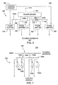
- Figure 2B depicts an elevation plan view of a beam produced by the antenna of the present invention
- Figure 3 depicts a block diagram of drive circuitry for the antenna array elements
- Figure 4 depicts a plan view of the antenna array elements
- Figure 5 depicts a vertical, cross sectional view of the antenna
- Figure 6 depicts an azimuth pattern produced by a planar antenna of the present invention.
- Figure 7 depicts a schematic diagram of a phase shifter that is used in the drive circuitry of Figure 3 .
- Figure 1 is a network diagram depicting an exemplary portion of a mesh network 100 as described in commonly assigned US patent application number 10/122,886, filed April 15, 2002 (Attorney Docket No. SKY/004-1) and application number 10/122,762, filed April 15, 2002 (Attorney Docket No. SKY/005-1).
- Network 100 comprises network access concentrators (SNAPs) 103, network access points (NAPs) 101 and network access nodes 102.
- Network traffic may be routed from a network access node 102 to a neighboring network access node 102.
- Such a neighboring network access node 102 may route such traffic to one of its neighboring network access nodes 102 and so on until a NAP 101 or a final destination network access node 102 is reached.
- nodes 102 may be in communication with one another but not with any node 101 to form a private wireless network.
- SNAPs 103 may be coupled to various backhauls 105, which backhauls 105 may be coupled to network 106.
- Network 106 may be coupled to an operations center (OC) 104.
- OC operations center
- Backhauls 105 may form a part of network 106.
- Network 106 may comprise a portion of the Internet, a private network, or the like. By private network, it is meant a network not connected to the Internet.
- NAPs 101 may be in communication with SNAPs 103 or network 106 via backhaul communication links 107. It should be understood that backhauls may be wired or wireless. In particular, backhauls coupled to NAPs 101 may have a wireless backhaul. In an embodiment, point-to-point communication is used as between a SNAP 103 and a NAP 101 in the Unlicensed National Information Infrastructure (UNII) band (e.g., using a frequency of about 5.8 Ghz). Though, at locations where wired connectivity is available, wired connectivity may be used.
- UNII Unlicensed National Information Infrastructure
- Network access nodes 102 are in wireless communication with at least one NAP 101 or node 102.
- nodes 102 or NAPs 101 may be configured for any of or some combination of broadcasting, point-to-point communication, and multicasting.
- broadcasting it is meant transmitting without singling out any particular target recipient among a potential audience of one or more recipients.
- point-to-point communication it is meant transmitting with singling out a particular target recipient among a potential audience of one or more recipients.
- multicasting it is meant transmitting with singling out a plurality of particular target recipients among a potential audience of recipients.
- communication between nodes 102, between NAPs 101, or between a NAP 101 and a node 102, described below is done in terms of point-to-point communication.
- Nodes 102 form, at least in part, a Wide Area Network (WAN) using in part wireless interlinks 108. More particularly, IEEE 802.11 a physical and link layer standards may be employed for communication in a range of 9 to 54 megabits per second (Mbits/s).
- WAN Wide Area Network
- IEEE 802.11 a physical and link layer standards may be employed for communication in a range of 9 to 54 megabits per second (Mbits/s).
- Communication slots as described herein are time slots with associated frequencies. However, one of ordinary skill in the art will understand that other types of communication spaces may be used, including without limitation codes, channels, and the like.
- the nodes of 102 may utilize both rooftop antennas 112 or a panel mount antenna 110 (i.e., a substantially planar antenna that is adapted to be mounted to a wall or window.
- the panel mount antenna 100 is capable of communicating with any mesh node 102 that is within line-of-sight to mounting location of the antenna 110.
- Figure 2A depicts a top plan view of the panel mount antenna 110 communicating with neighboring nodes 102A, 102B and 102C. While this figure shows communications with a signal neighbor node in each of the three possible beams, more than one neighbor node may reside in any of the beams.
- Figure 2B depicts a side view of panel mount antenna 110 communicating with rooftop node 102B.
- the panel mount antenna 110 synthesizes a single, directional beam that may be switched in a multitude of directions to connect to various nodes 102 within the neighborhood as well as avoid interference sources that may exist in the neighborhood.
- panel mount antenna 110 may communicate with node 102B using a beam that is directed perpendicular from the face of the antenna 110. In other instances, the beam may be shifted to communicate with other neighboring nodes 102A or 102C as described below.
- the panel mount antenna 110 does not actively control the elevation of the beam, i.e., the elevation of the beam is fixed to point at a right angle from the face of the antenna.
- the neighboring rooftop nodes are typically at a slight elevation relative to the panel mount antenna.
- the panel mount antenna has a vertical beamwidth that is sufficient to receive signals from nodes at a slight elevation relative to the panel mount antenna, to maximize the signal strength coupled to a rooftop mounted antenna, the panel mount antenna 110 may be tilted either physically or electrically. Empirical study indicates that an elevation of approximately five degrees is sufficient.
- the beam elevation may be electronically controlled in the same manner as the azimuth direction is controlled, as described below.
- Figure 3 depicts a block diagram of the antenna 110.
- the antenna 110 comprises a power delivery circuit 300 coupled to a plurality of array elements 302.
- the power delivery circuit 300 is mounted on one side of a circuit board and the array elements are mounted on the opposite side of the circuit board.
- Figure 4 depicts a top plan view of the array elements 302.
- Figure 5 depicts a vertical, cross sectional view of the antenna 110. To best understand the invention, the reader should simultaneously view Figures 3 , 4 , and 5 while reading the following description of the invention.
- the power delivery circuit 300 comprises a power divider 304, a plurality of attenuators 306, 308, 310, 312 and 314, and a pair of phase shifters 316 and 318.
- the input power to the array is applied to terminal 312, which has, for example, a 50-ohm input impedance.
- the antenna operates at approximately 5.8 GHz (e.g., frequencies in the UNII band).
- the power from port 312 is divided by the power divider 304 into five paths 305A-E, (i.e., a 1:5 power splitter).
- each output from the power divider contains attenuation (a thinning of the stripline) to adjust the relative amplitudes of the signals. To maintain a low cost, the attenuation is produced in this fixed manner.
- Four of the signals are then applied to phase shifters 316, 318, 320 and 322.
- the center signal (path 305C) is not phase shifted and forms a phase reference for the other paths 305A, B, D, E.
- phase shifters 316, 318, 320 and 322 operate by shifting the signals in discrete quantities using PIN diodes to vary the coupling within a hybrid coupler.
- Figure 7 depicts a schematic diagram of one of the phase shifters 316.
- the other phase shifters 318, 320 and 322 have the same structure.
- the phase shifter 316 comprises a hybrid coupler 700 and four PIN diodes 702A, 702B, 702C, 702D (collectively diodes 702).
- the diodes are spaced from one another along the branches 706A and 706B by an eighth of a wavelength and spaced from the cross arms 704A and 704B of the coupler 700 by an eighth of a wavelength.
- the diodes 702 can be selectively biased by control signals to form a short to ground.
- the phase shifters utilize the for PIN diodes 702 to shift the signal +90°, -90° or 0°.
- a control circuit 320 provides a bias voltage to the PIN diodes 702. When no bias is applied and the diodes form open circuits, the phase shift from input to output of the coupler 700 is -90 degrees. When diodes 702B and 702C are shorted to ground by biasing them, the phase shift through the coupler 700 is +90 degrees and, when diodes 702A and 702D are shorted to ground by biasing them, the phase shift through the coupler 700 is 0 degrees. These three discrete phase shifts may be applied to each of the four signal paths 305A, B, D, E. The shifted signal are applied to the array elements 302 through vias in the circuit board (see Figure 5 below).
- Figure 4 depicts one embodiment of an arrangement for the antenna elements within the array 302.
- This embodiment comprises five active columns 400, 402, 404, 406 and 408.
- Each column 400, 402, 404, 406, and 408 comprises eight elements 400A-H, 402A-H, 404A-H, 406A-H, and 408A-H.
- Each element is a radiating patch.
- the number of elements in the column determines the vertical beam width of the antenna. More or less than 8 elements may be used in a column.
- another type of radiating element such as a slot, dipole or other aperture, could be used.
- Each element in a column is connected to a neighboring element by a conductor 410.
- Microwave power is coupled to/from each column using a via 514 that is centrally located along the columns 402, 404, 406, 408.
- each column is spaced one half wavelength from an adjacent column.
- Other column spacings could be used with some degradation in the beam pattern side-lobes, one half wavelength spacing provides the optimum side-lobe levels.
- the embodiment can logically be considered to be a seven-column array where the "phantom" columns between 400 and 402 or between 406 and 408 have infinite attenuation and are not printed on the panel. This provides the performance of a seven-column antenna using the complexity and cost of a five-column circuit.
- column 400 is spaced about 5.17 cm from column 402, while columns 402, 404 and 406 are spaced from one another by about 2.59 cm and column 408 is spaced from column 406 by about 5.17cm.
- the elements within each column are equally spaced from one another by about 3.1 cm. Each element has the dimensions of about 0.9 cm by 1.4 cm. The size of each patch and the spacing between patches is wavelength dependent and would be scaled to design an antenna to other frequency bands.
- the phase shifters 316 and 318 control the phase of the signal applied to each of the columns such that the antenna beam may be shifted in the horizontal plane (azimuth), but is fixed in the vertical plane (elevation). As described above, to facilitate maximizing the signal strength coupled to rooftop nodes, the vertical spacing between the elements may be adjusted to provide a slight inclination to the main beam of the antenna pattern.
- FIG. 5 depicts a vertical, cross sectional view of the antenna 110.
- the antenna 110 comprises an enclosure 500 having a thickness of about 3 cm that houses a substrate, e.g., a multi-layer circuit board 502. The enclosure may be less than 3 cm thick depending upon the circuit configuration.
- the first layer 504 of metallization comprises the antenna elements 302
- the second layer 506 of metallization comprises a ground plane
- the third layer 508 comprises the driver circuit 300.
- a via 514 conductively couples each column of antenna elements 302 to their respective driver circuits 300.
- the third layer 508 also could support the transceiver and modem circuits 510.
- the antenna sends and receives microwave communications signals via the antenna elements, processes the signals within the transceiver/modem circuits and provides data input and output at port 512.
- the antenna 110 can be affixed to a window 516 via suction cups 518 or other form of adhesive. In a wall-mounted configuration, the antenna may be affixed to a wall using screws or bolts.
- the technique used to mount the planar antenna 110 can be adapted to any type of mounting configuration.
- the circuit board material is a low loss material useful for fabricating microwave circuits.
- One type of low cost material is available from Roger's Corporation as Material RO4003. This material provides a dielectric constant such that the circuit board for operation in the UNII band is 0.81 mm (0.032 inches) thick, as measured from the ground plane to the antenna elements.
- the total circuit board thickness is 1.65 mm (0.065 inches.)
- the total circuit board size is 178 mm (7 inches) by 254 mm (10 inches).
- the enclosure 500 has the approximate dimensions of 3 cm thick by 25 cm tall by 20 cm wide - a size that, when installed in a window, may easily be hidden behind a curtain.
- the antenna elements 302 of the first layer 504 may be separated from the ground plane 506 by a foam core or by an air gap.
- the drive circuitry can then be assembled on a conventional printed circuit board and mounted to the ground plane on the opposite side of the antenna elements.
- foam core or air gap based circuit construction will further lower the cost of the panel mount antenna.
- the spacing of the elements in the horizontal and vertical planes as well as the amplitude attenuation provided by the attenuators within the drive circuitry are adjusted to compensate for the impedance of the glass (or other material) against which the antenna is mounted.
- the single main beam of the antenna can be switched +/- 45° as well as the center.
- the antenna can be actively pointed toward the neighboring nodes to communicate with specific nodes as well as avoid unwanted interference from nodes that it is currently not communicating with as well as other microwave sources of interference.
- Figure 6 depicts the azimuth pattern 600 of the planar antenna 110 having the configuration described above for operation in the UNII band.
- the pattern 600 comprises a center beam 602, a right beam 604 and a left beam 606.
- the antenna 110 has a directive gain of 18.5 dBi with an elevation beamwidth of about 10 degrees and a azimuth beamwidth of about 47 degrees.
- the bandwidth of the antenna is 150 MHz.
Landscapes
- Engineering & Computer Science (AREA)
- Computer Networks & Wireless Communication (AREA)
- Variable-Direction Aerials And Aerial Arrays (AREA)
Claims (16)
- Système d'antenne de réseau maillé, comprenant :une antenne destinée à être facilement fixée à une vitre de fenêtre ou un mur communiquant avec des noeuds voisins, montés sur un toit, d'un réseau maillé comprenant :une antenne réseau possédant MxN éléments configurés pour synthétiser un diagramme de rayonnement, où M et N sont des nombres entiers supérieurs à un ; etun circuit d'attaque possédant un diviseur de puissance, dans lequel le diviseur de puissance divise la puissance de micro-ondes en M chemins de signal, pour fournir une puissance de micro-ondes à l'antenne réseau et une pluralité de circuits de déphasage pour commander la phase de la puissance de micro-ondes pour commuter une directivité d'un faisceau principal du diagramme de rayonnement dans P directions distinctes pour communiquer sélectivement avec les noeuds voisins, où P est un nombre entier supérieur à un ; et comprenant des atténuateurs (306 à 314) dans des chemins respectifs des M chemins de signal.
- Système d'antenne selon la revendication 1, dans lequel la pluralité de circuits de déphasage sont couplés à M-1 des M chemins de signal et la sortie de chaque circuit de déphasage est couplée à un élément d'antenne de l'antenne réseau, un des M chemins de signal étant couplé directement à un élément d'antenne de l'antenne réseau.
- Système d'antenne selon la revendication 1 ou 2, dans lequel M est 5 et N est 8.
- Système d'antenne selon la revendication 1, 2 ou 3, dans lequel les circuits de déphasage comprennent des coupleurs hybrides commutés qui, en réponse à un signal de commande, déphasent chacun les signaux sur les M-1 chemins selon une quantité de phase distincte correspondant à une des P directions distinctes.
- Système d'antenne selon la revendication 1, 2, 3 ou 4, dans lequel P est trois, correspondant à +45 degrés, au centre et à -45 degrés.
- Système d'antenne selon la revendication 5, dans lequel le déphasage distinct est au moins un parmi -90 degrés, 0 degrés et +90 degrés.
- Système d'antenne selon la revendication 6, dans lequel les déphasages distincts entraînent la direction du faisceau principal à 0 degrés, +45 degrés et -45 degrés.
- Système d'antenne selon une quelconque des revendications précédentes, dans lequel l'élévation du diagramme de rayonnement est fixe.
- Système d'antenne selon la revendication 8, dans lequel l'élévation du diagramme de rayonnement est fixée à une inclinaison par rapport à l'horizontale.
- Système d'antenne selon une quelconque des revendications précédentes, dans lequel le circuit d'attaque (300) est couplé à un circuit émetteur-récepteur et modem.
- Système d'antenne selon une quelconque des revendications précédentes, comprenant en outre :un enceinte (500) logeant l'antenne réseau et le circuit d'attaque, où ladite enceinte mesure approximativement 3 cm d'épaisseur.
- Système d'antenne selon une quelconque des revendications précédentes, dans lequel les M x W éléments d'antenne sont positionnés sur un substrat possédant des dimensions d'environ 25 cm par environ 20 cm.
- Système d'antenne selon une quelconque des revendications 1 à 10, comprenant en outre une enceinte (500) du circuit d'attaque et de l'antenne réseau, où l'enceinte comprend un élément adhésif.
- Système d'antenne selon la revendication 1, dans lequel l'élément adhésif (518) est adapté pour fixer l'enceinte à une surface plate.
- Système d'antenne selon une quelconque des revendications précédentes, comprenant une carte de circuit imprimé à couches multiples (502) possédant un premier côté et un second côté avec un plan de masse formé dans celle-ci, l'antenne réseau étant fixée au premier côté et le circuit d'attaque étant fixé au second côté.
- Système d'antenne selon une quelconque des revendications 1 à 14, comprenant un substrat central en mousse supportant les M x W éléments d'antenne (302).
Applications Claiming Priority (2)
| Application Number | Priority Date | Filing Date | Title |
|---|---|---|---|
| US10/607,405 US7053853B2 (en) | 2003-06-26 | 2003-06-26 | Planar antenna for a wireless mesh network |
| PCT/US2004/019427 WO2005004278A1 (fr) | 2003-06-26 | 2004-06-18 | Antenne plan pour reseau maille sans fil |
Publications (2)
| Publication Number | Publication Date |
|---|---|
| EP1636873A1 EP1636873A1 (fr) | 2006-03-22 |
| EP1636873B1 true EP1636873B1 (fr) | 2010-05-05 |
Family
ID=33540256
Family Applications (1)
| Application Number | Title | Priority Date | Filing Date |
|---|---|---|---|
| EP04755547A Expired - Lifetime EP1636873B1 (fr) | 2003-06-26 | 2004-06-18 | Antenne plan pour reseau maille sans fil |
Country Status (7)
| Country | Link |
|---|---|
| US (1) | US7053853B2 (fr) |
| EP (1) | EP1636873B1 (fr) |
| JP (1) | JP2007524273A (fr) |
| KR (1) | KR20060029626A (fr) |
| AT (1) | ATE467247T1 (fr) |
| DE (1) | DE602004027037D1 (fr) |
| WO (1) | WO2005004278A1 (fr) |
Families Citing this family (45)
| Publication number | Priority date | Publication date | Assignee | Title |
|---|---|---|---|---|
| US20040201525A1 (en) * | 2003-04-08 | 2004-10-14 | Bateman Blaine R. | Antenna arrays and methods of making the same |
| WO2005104142A1 (fr) * | 2004-04-22 | 2005-11-03 | Brother Kogyo Kabushiki Kaisha | Dispositif de communication radio par marqueurs |
| US8619662B2 (en) | 2004-11-05 | 2013-12-31 | Ruckus Wireless, Inc. | Unicast to multicast conversion |
| TWI391018B (zh) | 2004-11-05 | 2013-03-21 | Ruckus Wireless Inc | 藉由確認抑制之增強資訊量 |
| US7505447B2 (en) | 2004-11-05 | 2009-03-17 | Ruckus Wireless, Inc. | Systems and methods for improved data throughput in communications networks |
| US8638708B2 (en) | 2004-11-05 | 2014-01-28 | Ruckus Wireless, Inc. | MAC based mapping in IP based communications |
| US7586888B2 (en) * | 2005-02-17 | 2009-09-08 | Mobitrum Corporation | Method and system for mesh network embedded devices |
| US7630736B2 (en) * | 2005-10-11 | 2009-12-08 | Mobitrum Corporation | Method and system for spatial data input, manipulation and distribution via an adaptive wireless transceiver |
| US20070160020A1 (en) * | 2006-01-05 | 2007-07-12 | Robert Osann | Interleaved wireless mesh network |
| US8102868B2 (en) * | 2006-01-05 | 2012-01-24 | Folusha Forte B.V., Llc | Interleaved and directional wireless mesh network |
| US20070297366A1 (en) * | 2006-01-05 | 2007-12-27 | Robert Osann | Synchronized wireless mesh network |
| US20070183439A1 (en) * | 2006-01-05 | 2007-08-09 | Osann Robert Jr | Combined directional and mobile interleaved wireless mesh network |
| US8089881B2 (en) | 2006-03-03 | 2012-01-03 | Qualcomm Incorporated | Method and apparatus for increasing spectrum use efficiency in a mesh network |
| US7801058B2 (en) * | 2006-07-27 | 2010-09-21 | Mobitrum Corporation | Method and system for dynamic information exchange on mesh network devices |
| US8411590B2 (en) | 2006-07-27 | 2013-04-02 | Mobitrum Corporation | Mesh network remote control device |
| US8427979B1 (en) | 2006-07-27 | 2013-04-23 | Mobitrum Corporation | Method and system for dynamic information exchange on location aware mesh network devices |
| US8305935B2 (en) * | 2006-07-27 | 2012-11-06 | Mobitrum Corporation | Method and system for dynamic information exchange on location aware mesh network devices |
| USRE47894E1 (en) | 2006-07-27 | 2020-03-03 | Iii Holdings 2, Llc | Method and system for dynamic information exchange on location aware mesh network devices |
| US8305936B2 (en) | 2006-07-27 | 2012-11-06 | Mobitrum Corporation | Method and system for dynamic information exchange on a mesh network in a vehicle |
| US8547899B2 (en) | 2007-07-28 | 2013-10-01 | Ruckus Wireless, Inc. | Wireless network throughput enhancement through channel aware scheduling |
| CA2703546A1 (fr) | 2007-10-25 | 2009-04-30 | Trilliant Networks, Inc. | Gazometre ayant un materiau magnetique ultrasensible reconfigure sur un cadran de compteur et procede d'utilisation de la reconfiguration du compteur |
| US8171364B2 (en) | 2007-11-25 | 2012-05-01 | Trilliant Networks, Inc. | System and method for power outage and restoration notification in an advanced metering infrastructure network |
| EP2257884A4 (fr) * | 2007-11-25 | 2011-04-20 | Trilliant Networks Inc | Système et procédé pour émettre et recevoir des informations concernant un réseau zonal de voisinage |
| US20090135843A1 (en) * | 2007-11-25 | 2009-05-28 | Michel Veillette | System and method for operating mesh devices in multi-tree overlapping mesh networks |
| CA2705074A1 (fr) | 2007-11-25 | 2009-05-28 | Trilliant Networks, Inc. | Systeme et procede de regulation de la consommation d'energie |
| US8355343B2 (en) | 2008-01-11 | 2013-01-15 | Ruckus Wireless, Inc. | Determining associations in a mesh network |
| US20090189739A1 (en) * | 2008-01-25 | 2009-07-30 | Mobitrum Corporation | Passive voice enabled rfid devices |
| US20090231186A1 (en) * | 2008-02-06 | 2009-09-17 | Raysat Broadcasting Corp. | Compact electronically-steerable mobile satellite antenna system |
| WO2011060454A2 (fr) | 2009-11-16 | 2011-05-19 | Ruckus Wireless, Inc. | Création d'un réseau maillé avec des liaisons câblées et sans fil |
| US9979626B2 (en) * | 2009-11-16 | 2018-05-22 | Ruckus Wireless, Inc. | Establishing a mesh network with wired and wireless links |
| WO2012027634A1 (fr) * | 2010-08-27 | 2012-03-01 | Trilliant Networkd, Inc. | Système et procédé pour l'opération sans interférence d'émetteurs-récepteurs cositués |
| WO2012068045A2 (fr) | 2010-11-15 | 2012-05-24 | Trilliant Holdings Inc. | Système et procédé pour une communication sécurisée dans de multiples réseaux à l'aide d'un seul système radioélectrique |
| US9282383B2 (en) | 2011-01-14 | 2016-03-08 | Trilliant Incorporated | Process, device and system for volt/VAR optimization |
| US8970394B2 (en) | 2011-01-25 | 2015-03-03 | Trilliant Holdings Inc. | Aggregated real-time power outages/restoration reporting (RTPOR) in a secure mesh network |
| EP3285458B1 (fr) | 2011-02-10 | 2022-10-26 | Trilliant Holdings, Inc. | Dispositif et procédé pour faciliter des communications sécurisées sur un réseau cellulaire |
| US9041349B2 (en) | 2011-03-08 | 2015-05-26 | Trilliant Networks, Inc. | System and method for managing load distribution across a power grid |
| US9001787B1 (en) | 2011-09-20 | 2015-04-07 | Trilliant Networks Inc. | System and method for implementing handover of a hybrid communications module |
| KR101504041B1 (ko) * | 2013-02-14 | 2015-03-18 | 하이웨이브 주식회사 | 안테나 제어 방법 및 이를 실행하는 시스템 |
| WO2014126161A1 (fr) * | 2013-02-14 | 2014-08-21 | ハイウェーブ, インコ-ポレイティド | Procédé de commande d'antenne et système de commande d'antenne |
| US9692512B2 (en) * | 2013-03-15 | 2017-06-27 | Bae Systems Plc | Directional multiband antenna |
| US9401759B2 (en) | 2014-10-09 | 2016-07-26 | Hughes Network Systems, Llc | Multibeam coverage for a high altitude platform |
| GB2563574B (en) * | 2017-06-05 | 2021-08-04 | International Electric Company Ltd | A phased array antenna and apparatus incorporating the same |
| US11133586B2 (en) * | 2017-10-31 | 2021-09-28 | Communication Components Antenna Inc. | Antenna array with ABFN circuitry |
| US12118664B2 (en) | 2018-12-11 | 2024-10-15 | L3Vel, Llc | Systems and methods for designing and deploying wireless communication mesh networks |
| CR20210362A (es) * | 2018-12-11 | 2021-08-13 | Muhammad Ahsan Naim | Sistemas y métodos para diseñar y desplegar redes de comunicación inalámbrica de malla |
Citations (3)
| Publication number | Priority date | Publication date | Assignee | Title |
|---|---|---|---|---|
| EP0802579A2 (fr) * | 1996-04-15 | 1997-10-22 | Nippon Telegraph And Telephone Corporation | Antenne de secteurs multiples |
| EP0897230A2 (fr) * | 1997-08-12 | 1999-02-17 | Fujitsu Limited | Un système de réseau local sans fil et un émetteur-récepteur dans un tel système |
| WO2002039543A1 (fr) * | 2000-11-10 | 2002-05-16 | Am Group Corporation | Systeme d'antenne omnidirectionnelle agile pour communications sans fil |
Family Cites Families (47)
| Publication number | Priority date | Publication date | Assignee | Title |
|---|---|---|---|---|
| US4259674A (en) * | 1979-10-24 | 1981-03-31 | Bell Laboratories | Phased array antenna arrangement with filtering to reduce grating lobes |
| US4602257A (en) * | 1984-06-15 | 1986-07-22 | Grisham William H | Method of satellite operation using synthetic aperture radar addition holography for imaging |
| US4728960A (en) * | 1986-06-10 | 1988-03-01 | The United States Of America As Represented By The Secretary Of The Air Force | Multifunctional microstrip antennas |
| US4784147A (en) * | 1986-12-08 | 1988-11-15 | North American Philips Corporation | Method and apparatus for sidelobe suppression in scanning imaging systems |
| JPH01274505A (ja) | 1988-04-27 | 1989-11-02 | Mitsubishi Electric Corp | パツチアンテナ |
| JPH01279604A (ja) | 1988-05-06 | 1989-11-09 | Mitsubishi Electric Corp | マイクロストリップアンテナ |
| US5181042A (en) * | 1988-05-13 | 1993-01-19 | Yagi Antenna Co., Ltd. | Microstrip array antenna |
| GB8902421D0 (en) * | 1989-02-03 | 1989-03-22 | Secr Defence | Antenna array |
| JPH03171802A (ja) * | 1989-11-29 | 1991-07-25 | Mitsubishi Electric Corp | 大形平面アンテナ |
| JPH0644216U (ja) * | 1992-06-26 | 1994-06-10 | 三洋電機株式会社 | 平面アンテナ |
| JPH06314923A (ja) | 1993-04-19 | 1994-11-08 | Wireless Access Inc | 小型二重リングマイクロストリップアンテナ |
| JPH06334429A (ja) * | 1993-05-26 | 1994-12-02 | Toyota Central Res & Dev Lab Inc | 追尾アンテナ装置 |
| US5548813A (en) * | 1994-03-24 | 1996-08-20 | Ericsson Inc. | Phased array cellular base station and associated methods for enhanced power efficiency |
| US5832389A (en) * | 1994-03-24 | 1998-11-03 | Ericsson Inc. | Wideband digitization systems and methods for cellular radiotelephones |
| US5751248A (en) * | 1994-10-13 | 1998-05-12 | The Boeing Company | Phased array beam controller using integrated electro-optic circuits |
| US5686928A (en) * | 1995-10-13 | 1997-11-11 | Lockheed Martin Corporation | Phased array antenna for radio frequency identification |
| CA2241128A1 (fr) * | 1997-06-30 | 1998-12-30 | Sony International (Europe) Gmbh | Antenne reseau a commande de phase imprimee a large bande pour applications micrometriques et millimetriques |
| US5936592A (en) * | 1998-06-05 | 1999-08-10 | Ramanujam; Parthasarathy | Reconfigurable multiple beam satellite reflector antenna with an array feed |
| US6229486B1 (en) * | 1998-09-10 | 2001-05-08 | David James Krile | Subscriber based smart antenna |
| DE69938413T2 (de) * | 1998-09-30 | 2009-04-23 | Anritsu Corp. | Planare antenne und verfahren zur herstellung derselben |
| US6583760B2 (en) * | 1998-12-17 | 2003-06-24 | Metawave Communications Corporation | Dual mode switched beam antenna |
| US6292133B1 (en) * | 1999-07-26 | 2001-09-18 | Harris Corporation | Array antenna with selectable scan angles |
| US6266011B1 (en) * | 1999-09-30 | 2001-07-24 | Rockwell Science Center, Llc | Electronically scanned phased array antenna system and method with scan control independent of radiating frequency |
| US6426814B1 (en) * | 1999-10-13 | 2002-07-30 | Caly Corporation | Spatially switched router for wireless data packets |
| US6335703B1 (en) | 2000-02-29 | 2002-01-01 | Lucent Technologies Inc. | Patch antenna with finite ground plane |
| JP2001244717A (ja) | 2000-03-02 | 2001-09-07 | Matsushita Electric Ind Co Ltd | 無線情報家電装置 |
| DE10012080C1 (de) * | 2000-03-14 | 2001-10-31 | Daimler Chrysler Ag | Antennenarray und Verfahren zum Betrieb eines Antennenarrays |
| US7096257B2 (en) * | 2000-06-15 | 2006-08-22 | Forster Energy Llc | Automatic assignment of addresses to nodes in a network |
| US6407705B1 (en) * | 2000-06-27 | 2002-06-18 | Mohamed Said Sanad | Compact broadband high efficiency microstrip antenna for wireless modems |
| US6538603B1 (en) * | 2000-07-21 | 2003-03-25 | Paratek Microwave, Inc. | Phased array antennas incorporating voltage-tunable phase shifters |
| US6433742B1 (en) * | 2000-10-19 | 2002-08-13 | Magis Networks, Inc. | Diversity antenna structure for wireless communications |
| US6438367B1 (en) * | 2000-11-09 | 2002-08-20 | Magis Networks, Inc. | Transmission security for wireless communications |
| US6456245B1 (en) * | 2000-12-13 | 2002-09-24 | Magis Networks, Inc. | Card-based diversity antenna structure for wireless communications |
| GB0030932D0 (en) * | 2000-12-19 | 2001-01-31 | Radiant Networks Plc | Antenna apparatus, communications apparatus and method of transmission |
| US6369770B1 (en) * | 2001-01-31 | 2002-04-09 | Tantivy Communications, Inc. | Closely spaced antenna array |
| US20020137547A1 (en) * | 2001-02-07 | 2002-09-26 | Judson Bruce A. | Antenna array and method therefor |
| US6498754B2 (en) * | 2001-02-15 | 2002-12-24 | Digeo, Inc. | Memory array organization for static arrays |
| JP4569015B2 (ja) * | 2001-02-28 | 2010-10-27 | ソニー株式会社 | 広帯域アレイアンテナ |
| CA2444433A1 (fr) * | 2001-04-18 | 2002-10-31 | Skypilot Network, Inc. | Protocole d'acces aux voies d'un reseau a adaptation des interferences et des charges |
| US7616600B2 (en) * | 2001-04-18 | 2009-11-10 | Trilliant Networks, Inc. | Wireless mesh network node |
| US6529162B2 (en) * | 2001-05-17 | 2003-03-04 | Irwin L. Newberg | Phased array antenna system with virtual time delay beam steering |
| US6876337B2 (en) * | 2001-07-30 | 2005-04-05 | Toyon Research Corporation | Small controlled parasitic antenna system and method for controlling same to optimally improve signal quality |
| US6801160B2 (en) * | 2001-08-27 | 2004-10-05 | Herbert Jefferson Henderson | Dynamic multi-beam antenna using dielectrically tunable phase shifters |
| US6710742B1 (en) * | 2001-10-23 | 2004-03-23 | Kathrein-Werke Kg | Active antenna roof top system and method |
| JP3802405B2 (ja) * | 2001-11-30 | 2006-07-26 | 日本放送協会 | アクティブスロットアンテナ及びアクティブスロットアレーアンテナ及びそれを用いた送信装置と受信装置 |
| US6816116B2 (en) * | 2002-03-22 | 2004-11-09 | Quanta Computer, Inc. | Smart antenna for portable devices |
| US6765530B1 (en) * | 2002-07-16 | 2004-07-20 | Ball Aerospace & Technologies Corp. | Array antenna having pairs of antenna elements |
-
2003
- 2003-06-26 US US10/607,405 patent/US7053853B2/en not_active Expired - Fee Related
-
2004
- 2004-06-18 DE DE602004027037T patent/DE602004027037D1/de not_active Expired - Fee Related
- 2004-06-18 AT AT04755547T patent/ATE467247T1/de not_active IP Right Cessation
- 2004-06-18 EP EP04755547A patent/EP1636873B1/fr not_active Expired - Lifetime
- 2004-06-18 JP JP2006517363A patent/JP2007524273A/ja active Pending
- 2004-06-18 KR KR1020057024751A patent/KR20060029626A/ko not_active Ceased
- 2004-06-18 WO PCT/US2004/019427 patent/WO2005004278A1/fr not_active Ceased
Patent Citations (3)
| Publication number | Priority date | Publication date | Assignee | Title |
|---|---|---|---|---|
| EP0802579A2 (fr) * | 1996-04-15 | 1997-10-22 | Nippon Telegraph And Telephone Corporation | Antenne de secteurs multiples |
| EP0897230A2 (fr) * | 1997-08-12 | 1999-02-17 | Fujitsu Limited | Un système de réseau local sans fil et un émetteur-récepteur dans un tel système |
| WO2002039543A1 (fr) * | 2000-11-10 | 2002-05-16 | Am Group Corporation | Systeme d'antenne omnidirectionnelle agile pour communications sans fil |
Also Published As
| Publication number | Publication date |
|---|---|
| DE602004027037D1 (fr) | 2010-06-17 |
| ATE467247T1 (de) | 2010-05-15 |
| US7053853B2 (en) | 2006-05-30 |
| WO2005004278A1 (fr) | 2005-01-13 |
| JP2007524273A (ja) | 2007-08-23 |
| KR20060029626A (ko) | 2006-04-06 |
| EP1636873A1 (fr) | 2006-03-22 |
| US20040263390A1 (en) | 2004-12-30 |
Similar Documents
| Publication | Publication Date | Title |
|---|---|---|
| EP1636873B1 (fr) | Antenne plan pour reseau maille sans fil | |
| US6864853B2 (en) | Combination directional/omnidirectional antenna | |
| EP4429025A2 (fr) | Éléments rayonnants ayant des tiges d'alimentation inclinées et antennes de station de base les comprenant | |
| KR100746930B1 (ko) | L자형 실내 안테나 | |
| EP1751821B1 (fr) | Antenne dipole orientee | |
| US9761937B2 (en) | Fragmented aperture for the Ka/K/Ku frequency bands | |
| US20030052828A1 (en) | Co-located antenna array for passive beam forming | |
| EP0976171B1 (fr) | Procede d'amelioration des parametres de performances d'une antenne et systeme antenne | |
| WO2005062428A1 (fr) | Antenne de station de base a double polarisation et a large bande a diagramme de rayonnement optimise du faisceau horizontal et a inclinaison variable du faisceau | |
| WO2002031908A2 (fr) | Antenne interieure | |
| US11411301B2 (en) | Compact multiband feed for small cell base station antennas | |
| EP1406346B1 (fr) | Réseau d'antennes formé par éléments d'antenne patch à cavité et couplage par proximité et alimenté parallèle-série par ligne microbande | |
| US6049305A (en) | Compact antenna for low and medium earth orbit satellite communication systems | |
| CN100375332C (zh) | 通信设备、传输方法和天线设备 | |
| US10374292B2 (en) | Wireless backhaul network using traveling wave antennas | |
| US20250046999A1 (en) | High performance patch-type radiating elements for massive mimo communication systems | |
| KR100748337B1 (ko) | 이중편파 다이버시티 능동형 마이크로스트립 배열 안테나 | |
| KR20080028408A (ko) | 개선된 중계기 안테나 | |
| KR20020041771A (ko) | 아이엠티2000용 마이크로스트립 패치 어레이 안테나 | |
| WO2019136255A1 (fr) | Systèmes de dispositifs de réseau d'antennes de coin et procédés | |
| CN101218762B (zh) | 经过改进的中继器天线 | |
| KR100449836B1 (ko) | 송/수신 겸용 광대역 마이크로스트립 패치 안테나 및 이를 배열한 배열 안테나 | |
| KR20190117965A (ko) | 밀리미터파용 균일 원형 배열 안테나 | |
| KR20020061717A (ko) | 마이크로스트립 빔 성형 안테나 | |
| Hettak et al. | Millimeter wave mobile access system with intelligent antenna and radio on fiber |
Legal Events
| Date | Code | Title | Description |
|---|---|---|---|
| PUAI | Public reference made under article 153(3) epc to a published international application that has entered the european phase |
Free format text: ORIGINAL CODE: 0009012 |
|
| 17P | Request for examination filed |
Effective date: 20051213 |
|
| AK | Designated contracting states |
Kind code of ref document: A1 Designated state(s): AT BE BG CH CY CZ DE DK EE ES FI FR GB GR HU IE IT LI LU MC NL PL PT RO SE SI SK TR |
|
| 17Q | First examination report despatched |
Effective date: 20060712 |
|
| DAX | Request for extension of the european patent (deleted) | ||
| RAP1 | Party data changed (applicant data changed or rights of an application transferred) |
Owner name: SKYPILOT NETWORKS, INC. |
|
| GRAP | Despatch of communication of intention to grant a patent |
Free format text: ORIGINAL CODE: EPIDOSNIGR1 |
|
| RAP1 | Party data changed (applicant data changed or rights of an application transferred) |
Owner name: TRILLIANT NETWORKS, INC. |
|
| GRAS | Grant fee paid |
Free format text: ORIGINAL CODE: EPIDOSNIGR3 |
|
| GRAA | (expected) grant |
Free format text: ORIGINAL CODE: 0009210 |
|
| AK | Designated contracting states |
Kind code of ref document: B1 Designated state(s): AT BE BG CH CY CZ DE DK EE ES FI FR GB GR HU IE IT LI LU MC NL PL PT RO SE SI SK TR |
|
| REG | Reference to a national code |
Ref country code: GB Ref legal event code: FG4D |
|
| REG | Reference to a national code |
Ref country code: CH Ref legal event code: EP |
|
| REG | Reference to a national code |
Ref country code: IE Ref legal event code: FG4D |
|
| REF | Corresponds to: |
Ref document number: 602004027037 Country of ref document: DE Date of ref document: 20100617 Kind code of ref document: P |
|
| REG | Reference to a national code |
Ref country code: NL Ref legal event code: VDEP Effective date: 20100505 |
|
| PG25 | Lapsed in a contracting state [announced via postgrant information from national office to epo] |
Ref country code: ES Free format text: LAPSE BECAUSE OF FAILURE TO SUBMIT A TRANSLATION OF THE DESCRIPTION OR TO PAY THE FEE WITHIN THE PRESCRIBED TIME-LIMIT Effective date: 20100816 Ref country code: SE Free format text: LAPSE BECAUSE OF FAILURE TO SUBMIT A TRANSLATION OF THE DESCRIPTION OR TO PAY THE FEE WITHIN THE PRESCRIBED TIME-LIMIT Effective date: 20100505 Ref country code: NL Free format text: LAPSE BECAUSE OF FAILURE TO SUBMIT A TRANSLATION OF THE DESCRIPTION OR TO PAY THE FEE WITHIN THE PRESCRIBED TIME-LIMIT Effective date: 20100505 |
|
| PG25 | Lapsed in a contracting state [announced via postgrant information from national office to epo] |
Ref country code: SI Free format text: LAPSE BECAUSE OF FAILURE TO SUBMIT A TRANSLATION OF THE DESCRIPTION OR TO PAY THE FEE WITHIN THE PRESCRIBED TIME-LIMIT Effective date: 20100505 Ref country code: AT Free format text: LAPSE BECAUSE OF FAILURE TO SUBMIT A TRANSLATION OF THE DESCRIPTION OR TO PAY THE FEE WITHIN THE PRESCRIBED TIME-LIMIT Effective date: 20100505 Ref country code: FI Free format text: LAPSE BECAUSE OF FAILURE TO SUBMIT A TRANSLATION OF THE DESCRIPTION OR TO PAY THE FEE WITHIN THE PRESCRIBED TIME-LIMIT Effective date: 20100505 |
|
| PG25 | Lapsed in a contracting state [announced via postgrant information from national office to epo] |
Ref country code: PL Free format text: LAPSE BECAUSE OF FAILURE TO SUBMIT A TRANSLATION OF THE DESCRIPTION OR TO PAY THE FEE WITHIN THE PRESCRIBED TIME-LIMIT Effective date: 20100505 Ref country code: GR Free format text: LAPSE BECAUSE OF FAILURE TO SUBMIT A TRANSLATION OF THE DESCRIPTION OR TO PAY THE FEE WITHIN THE PRESCRIBED TIME-LIMIT Effective date: 20100806 Ref country code: CY Free format text: LAPSE BECAUSE OF FAILURE TO SUBMIT A TRANSLATION OF THE DESCRIPTION OR TO PAY THE FEE WITHIN THE PRESCRIBED TIME-LIMIT Effective date: 20100505 |
|
| PG25 | Lapsed in a contracting state [announced via postgrant information from national office to epo] |
Ref country code: MC Free format text: LAPSE BECAUSE OF NON-PAYMENT OF DUE FEES Effective date: 20100630 Ref country code: EE Free format text: LAPSE BECAUSE OF FAILURE TO SUBMIT A TRANSLATION OF THE DESCRIPTION OR TO PAY THE FEE WITHIN THE PRESCRIBED TIME-LIMIT Effective date: 20100505 Ref country code: DK Free format text: LAPSE BECAUSE OF FAILURE TO SUBMIT A TRANSLATION OF THE DESCRIPTION OR TO PAY THE FEE WITHIN THE PRESCRIBED TIME-LIMIT Effective date: 20100505 Ref country code: PT Free format text: LAPSE BECAUSE OF FAILURE TO SUBMIT A TRANSLATION OF THE DESCRIPTION OR TO PAY THE FEE WITHIN THE PRESCRIBED TIME-LIMIT Effective date: 20100906 |
|
| REG | Reference to a national code |
Ref country code: CH Ref legal event code: PL |
|
| PG25 | Lapsed in a contracting state [announced via postgrant information from national office to epo] |
Ref country code: BE Free format text: LAPSE BECAUSE OF FAILURE TO SUBMIT A TRANSLATION OF THE DESCRIPTION OR TO PAY THE FEE WITHIN THE PRESCRIBED TIME-LIMIT Effective date: 20100505 Ref country code: RO Free format text: LAPSE BECAUSE OF FAILURE TO SUBMIT A TRANSLATION OF THE DESCRIPTION OR TO PAY THE FEE WITHIN THE PRESCRIBED TIME-LIMIT Effective date: 20100505 Ref country code: SK Free format text: LAPSE BECAUSE OF FAILURE TO SUBMIT A TRANSLATION OF THE DESCRIPTION OR TO PAY THE FEE WITHIN THE PRESCRIBED TIME-LIMIT Effective date: 20100505 Ref country code: CZ Free format text: LAPSE BECAUSE OF FAILURE TO SUBMIT A TRANSLATION OF THE DESCRIPTION OR TO PAY THE FEE WITHIN THE PRESCRIBED TIME-LIMIT Effective date: 20100505 |
|
| PLBE | No opposition filed within time limit |
Free format text: ORIGINAL CODE: 0009261 |
|
| STAA | Information on the status of an ep patent application or granted ep patent |
Free format text: STATUS: NO OPPOSITION FILED WITHIN TIME LIMIT |
|
| REG | Reference to a national code |
Ref country code: FR Ref legal event code: ST Effective date: 20110228 |
|
| PG25 | Lapsed in a contracting state [announced via postgrant information from national office to epo] |
Ref country code: IT Free format text: LAPSE BECAUSE OF FAILURE TO SUBMIT A TRANSLATION OF THE DESCRIPTION OR TO PAY THE FEE WITHIN THE PRESCRIBED TIME-LIMIT Effective date: 20100505 |
|
| 26N | No opposition filed |
Effective date: 20110208 |
|
| PG25 | Lapsed in a contracting state [announced via postgrant information from national office to epo] |
Ref country code: DE Free format text: LAPSE BECAUSE OF NON-PAYMENT OF DUE FEES Effective date: 20110101 Ref country code: CH Free format text: LAPSE BECAUSE OF NON-PAYMENT OF DUE FEES Effective date: 20100630 Ref country code: IE Free format text: LAPSE BECAUSE OF NON-PAYMENT OF DUE FEES Effective date: 20100618 Ref country code: LI Free format text: LAPSE BECAUSE OF NON-PAYMENT OF DUE FEES Effective date: 20100630 |
|
| PG25 | Lapsed in a contracting state [announced via postgrant information from national office to epo] |
Ref country code: FR Free format text: LAPSE BECAUSE OF NON-PAYMENT OF DUE FEES Effective date: 20100705 |
|
| PG25 | Lapsed in a contracting state [announced via postgrant information from national office to epo] |
Ref country code: HU Free format text: LAPSE BECAUSE OF FAILURE TO SUBMIT A TRANSLATION OF THE DESCRIPTION OR TO PAY THE FEE WITHIN THE PRESCRIBED TIME-LIMIT Effective date: 20101106 Ref country code: BG Free format text: LAPSE BECAUSE OF FAILURE TO SUBMIT A TRANSLATION OF THE DESCRIPTION OR TO PAY THE FEE WITHIN THE PRESCRIBED TIME-LIMIT Effective date: 20100505 Ref country code: LU Free format text: LAPSE BECAUSE OF NON-PAYMENT OF DUE FEES Effective date: 20100618 |
|
| PG25 | Lapsed in a contracting state [announced via postgrant information from national office to epo] |
Ref country code: TR Free format text: LAPSE BECAUSE OF FAILURE TO SUBMIT A TRANSLATION OF THE DESCRIPTION OR TO PAY THE FEE WITHIN THE PRESCRIBED TIME-LIMIT Effective date: 20100505 |
|
| PG25 | Lapsed in a contracting state [announced via postgrant information from national office to epo] |
Ref country code: BG Free format text: LAPSE BECAUSE OF FAILURE TO SUBMIT A TRANSLATION OF THE DESCRIPTION OR TO PAY THE FEE WITHIN THE PRESCRIBED TIME-LIMIT Effective date: 20100805 |
|
| PGFP | Annual fee paid to national office [announced via postgrant information from national office to epo] |
Ref country code: GB Payment date: 20160627 Year of fee payment: 13 |
|
| GBPC | Gb: european patent ceased through non-payment of renewal fee |
Effective date: 20170618 |
|
| PG25 | Lapsed in a contracting state [announced via postgrant information from national office to epo] |
Ref country code: GB Free format text: LAPSE BECAUSE OF NON-PAYMENT OF DUE FEES Effective date: 20170618 |
|
| REG | Reference to a national code |
Ref country code: GB Ref legal event code: 732E Free format text: REGISTERED BETWEEN 20191219 AND 20191224 |