EP1637018B1 - Gehäuse, insbesondere für eine leiterplatte oder dergleichen, sowie verfahren zu dessen herstellung - Google Patents
Gehäuse, insbesondere für eine leiterplatte oder dergleichen, sowie verfahren zu dessen herstellung Download PDFInfo
- Publication number
- EP1637018B1 EP1637018B1 EP04732598A EP04732598A EP1637018B1 EP 1637018 B1 EP1637018 B1 EP 1637018B1 EP 04732598 A EP04732598 A EP 04732598A EP 04732598 A EP04732598 A EP 04732598A EP 1637018 B1 EP1637018 B1 EP 1637018B1
- Authority
- EP
- European Patent Office
- Prior art keywords
- housing
- bore
- receptacle
- lug
- tab
- Prior art date
- Legal status (The legal status is an assumption and is not a legal conclusion. Google has not performed a legal analysis and makes no representation as to the accuracy of the status listed.)
- Expired - Lifetime
Links
Images

Classifications
-
- H—ELECTRICITY
- H05—ELECTRIC TECHNIQUES NOT OTHERWISE PROVIDED FOR
- H05K—PRINTED CIRCUITS; CASINGS OR CONSTRUCTIONAL DETAILS OF ELECTRIC APPARATUS; MANUFACTURE OF ASSEMBLAGES OF ELECTRICAL COMPONENTS
- H05K5/00—Casings, cabinets or drawers for electric apparatus
- H05K5/10—Casings, cabinets or drawers for electric apparatus comprising several parts forming a closed casing
- H05K5/13—Casings, cabinets or drawers for electric apparatus comprising several parts forming a closed casing assembled by screws
Definitions
- the present invention relates to a housing, in particular a housing intended to contain a printed circuit (also called in English Printed Circuit Board or PCB) or the like, and a method for obtaining it.
- a printed circuit also called in English Printed Circuit Board or PCB
- the object of the present invention is therefore to provide a housing which, by its design, prevents a chip from reaching the printed circuit intended to take place inside it.
- the proposed housing has no significant additional cost compared to a housing of the prior art.
- a housing in particular a housing intended to contain electronic components or the like, comprising a support having a bore for receiving a fixing screw.
- this housing further comprises, facing the bore for receiving the screw, a receptacle extending inside the housing.
- the receptacle extends from the support having the bore and forms with this support, with the exception of the area where the bore is located, a closed space. Once the screw is in place, the chips are perfectly locked and can not create short circuits at the components.
- the receptacle is for example obtained by stamping. It presents, in a preferred embodiment, a generally tubular shape, of circular section and closed at its end opposite the bore.
- the support from the housing having the bore may be in the form of a tongue folded relative to a wall of the housing. Then, advantageously, the receptacle is carried by a folded tab on the tongue.
- Such a blank sheet makes it possible to produce a case according to the invention from a single piece of metal.
- a substantially rectangular cutout is advantageously provided between the tab and the tongue so as to form a hinge.
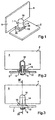
- the figure 1 shows, seen from below, the fixing of a cover 2 on a housing 4.
- the cover 2 can be a sheet metal cover, or any other material, or it can also be a printed circuit board.
- the components fixed on this printed circuit are then oriented towards the inside of the housing when this printed circuit is fixed on the housing 4.
- a screw 6 for holding the cover 2 on the housing 4. This is preferably a self-forming screw that allows excellent fixation without the use of a nut.
- the cover 2 is positioned perpendicularly to this side wall 8.
- the side wall 8 has a tab 10 in one piece with the side wall 8 and folded relative to this wall at right angles to the inside of the housing.
- this tongue 10 is made a bore 12 for receiving the self-forming screw 6. It is provided, in known manner, that this bore is of smaller diameter than the diameter of the rod of the screw 6.
- the screw 6 when it is screwed into the bore 12, deforms the tongue 10 around the bore 12 so as to form a tapping in the tongue 10.
- the tongue 10 carries a receptacle 14. This is of substantially circular cylindrical shape and is tubular. It extends perpendicular to the plane of the tongue 10 (itself parallel to the lid 2).
- the receptacle 14 rests on the tongue 10. It is open on the side of this tongue 10 and is closed at its opposite end.
- the bottom wall 16, that is to say the one lying opposite the tongue 10, is for example of hemispherical shape.
- the edge of the receptacle, on the side of the tongue 10 surrounds the bore 12 formed in this tongue 10. The receptacle 14 thus creates a closed space which is open only to the bore 12 and which is completely closed when a screw 6 is in this bore.
- the receptacle 14 is formed on a tab 18 forming a single piece with the tongue 10. This tab 18 is folded at 180 ° with respect to the tongue 10. The tab 18 is connected to the tongue 10 by two thin strips of metal forming a hinge 20.
- the receptacle 14 and its bottom wall 16 are for example obtained by stamping the tab 18.
- the tongue 10 and the receptacle 14 may advantageously form a single piece with the wall 8 of the casing 4.
- the tongue 10 is obtained for fastening the screw 6 and the receptacle 14 serving as a trap. shavings for the chips produced during the first screwing of the self-forming screw 6 into its bore 12.
- the figure 5 shows after cutting and before folding the detail of a sheet used to produce the housing 4 shown in FIGS. Figures 1 to 4 .
- the wall 8 the tongue 10 in which is formed the bore 12, the lug 18 carrying the receptacle 14 and connected to the tongue 10 by the hinge 20.
- the tongue 10 is attached to the wall 8.
- the tab 18 is connected to the wall 8 only via the tongue 10 and the hinge 20.
- the sheet blank used to produce the housing 4 has a rectangular cutout 22 separating the tongue 10 of the tab 18.
- the stamping forming the receptacle 14 can be made immediately before cutting the sheet. This operation is done on the same press with a suitable tool. Once the cut is made, two bends are made successively.
- the tab 18 is folded by 180 ° about a first axis of folding 24 and the assembly formed by the tab 18 and the tongue 10 is bent 90 ° about a second axis of folding 26 to be folded towards the Inside of the casing 4.
- the tongue 10 and the tab 18 are not necessarily placed on an edge of the side wall 8, but can be obtained at any point thereof, forming a cutout of said wall 8 on the periphery of the wall.
- the shape of the receptacle may be different from that described.
- the process of obtaining can also be different. It can indeed provide a receptacle consisting of a separate part of the housing. For example in the case of a housing for which welding operations are necessary, it can be expected to come weld a piece at a bore for receiving a self-forming screw so as to form the chip trap.
Landscapes
- Engineering & Computer Science (AREA)
- Microelectronics & Electronic Packaging (AREA)
- Casings For Electric Apparatus (AREA)
- Mounting Of Printed Circuit Boards And The Like (AREA)
- Connection Of Plates (AREA)
Claims (9)
- Gehäuse (4), insbesondere ein Gehäuse (4) für elektronische Bauelemente oder dergleichen, das eine Auflage (1) umfasst, die eine Bohrung (12) zur Aufnahme einer Befestigungsschraube (6) aufweist, dadurch gekennzeichnet, dass es außerdem gegenüber der Bohrung (12) zur Aufnahme der Schraube (6) eine Aufnahme (14) umfasst, die sich im Inneren des Gehäuses erstreckt.
- Gehäuse nach Anspruch 1, dadurch gekennzeichnet, dass die Aufnahme (14) sich von der Auflage (1) aus erstreckt, die die Bohrung (12) umfasst, und mit dieser Auflage (1) mit Ausnahme des Bereichs, in dem sich die Bohrung (12) befindet, einen geschlossenen Raum bildet.
- Gehäuse nach einem der Ansprüche 1 oder 2, dadurch gekennzeichnet, dass die Aufnahme (14) durch Tiefziehen erhalten wird.
- Gehäuse nach einem der Ansprüche 1 bis 3, dadurch gekennzeichnet, dass die Aufnahme (14) insgesamt röhrenförmig mit kreisförmigem Querschnitt ist, und an ihrem Ende gegenüber der Bohrung (12) geschlossen ist.
- Gehäuse nach einem der Ansprüche 1 bis 4, dadurch gekennzeichnet, dass die Auflage (1), die die Bohrung (12) aufweist, in Form einer Zunge (10) auftritt, die in Bezug auf eine Wand (8) des Gehäuses umgebogen ist.
- Gehäuse nach Anspruch 5, dadurch gekennzeichnet, dass die Aufnahme (14) von einer Lasche (18) getragen wird, die auf der Zunge (10) umgebogen ist.
- Geschnittene und tiefgezogene Blechscheibe, dadurch gekennzeichnet, dass sie umfasst:- eine im Wesentlichen rechteckige Zunge (10), die durch eine erste Seite auf im Wesentlichen ihrer gesamten Länge an der übrigen Blechscheibe befestigt ist,- eine Bohrung (12), die in der Zunge (10) ausgeführt ist,- eine Lasche (18), die mit der Zunge (10) durch eine benachbarte Seite der ersten Seite verbunden ist, und- eine Aufnahme (14), die durch Tiefziehen erhalten wird, das im Bereich der Lasche (18) ausgeführt wird.
- Blechscheibe nach Anspruch 7, dadurch gekennzeichnet, dass sie einen im Wesentlichen rechteckigen Zuschnitt (22) aufweist, der zwischen der Lasche (18) und der Zunge (10) ausgeführt ist, so dass er ein Scharnier (20) bildet.
- Verfahren zur Herstellung eines Gehäuses 4, in dem eine Blechscheibe geschnitten und anschließend gebogen wird, dadurch gekennzeichnet, dass es die folgenden Schritte umfasst:- Ausführen einer Blechscheibe nach einem der Ansprüche 7 oder 8,- Flachbiegen der Lasche (18) auf der Zunge (10), und- Biegen der Zunge (10) im rechten Winkel in Bezug auf die Blechscheibe,wobei die zwei letzten Schritte in einer beliebigen Reihenfolge ausgeführt werden können.
Applications Claiming Priority (2)
| Application Number | Priority Date | Filing Date | Title |
|---|---|---|---|
| FR0307669A FR2856882B1 (fr) | 2003-06-25 | 2003-06-25 | Boitier, notamment boitier destine a contenir un circuit imprime ou similaire et procede pour l'obtention de celui-ci |
| PCT/EP2004/005136 WO2004114735A1 (fr) | 2003-06-25 | 2004-05-13 | Boitier, notamment boitier destine a contenir un circuit imprime ou similaire et procede pour l’obtention de celui-ci |
Publications (2)
| Publication Number | Publication Date |
|---|---|
| EP1637018A1 EP1637018A1 (de) | 2006-03-22 |
| EP1637018B1 true EP1637018B1 (de) | 2008-07-09 |
Family
ID=33515395
Family Applications (1)
| Application Number | Title | Priority Date | Filing Date |
|---|---|---|---|
| EP04732598A Expired - Lifetime EP1637018B1 (de) | 2003-06-25 | 2004-05-13 | Gehäuse, insbesondere für eine leiterplatte oder dergleichen, sowie verfahren zu dessen herstellung |
Country Status (7)
| Country | Link |
|---|---|
| US (1) | US20060138914A1 (de) |
| EP (1) | EP1637018B1 (de) |
| JP (1) | JP2007507085A (de) |
| CN (1) | CN100518453C (de) |
| DE (1) | DE602004014929D1 (de) |
| FR (1) | FR2856882B1 (de) |
| WO (1) | WO2004114735A1 (de) |
Families Citing this family (5)
| Publication number | Priority date | Publication date | Assignee | Title |
|---|---|---|---|---|
| FR2886507B1 (fr) * | 2005-05-25 | 2010-11-05 | Siemens Vdo Automotive | Boitier destine a contenir des composants electroniques ou similaires |
| DE102007052152A1 (de) * | 2007-10-31 | 2009-05-07 | Robert Bosch Gmbh | Navigationssystem |
| JP2010092231A (ja) * | 2008-10-07 | 2010-04-22 | Panasonic Corp | 情報処理装置 |
| JP6173227B2 (ja) * | 2014-01-27 | 2017-08-02 | 三菱電機株式会社 | ネジ締結構造および電子機器 |
| FR3121005B1 (fr) * | 2021-03-17 | 2026-01-02 | Vitesco Technologies | Element metallique de boitier de protection d’un calculateur pour vehicule automobile |
Family Cites Families (18)
| Publication number | Priority date | Publication date | Assignee | Title |
|---|---|---|---|---|
| US112870A (en) * | 1871-03-21 | Improvement in combined potato-planters and diggers | ||
| US2797720A (en) * | 1953-12-14 | 1957-07-02 | Gen Motors Corp | Sheet metal nut with screw slot having frangible serrations |
| US2878905A (en) * | 1956-03-05 | 1959-03-24 | Gregg C Langermeier | Molded cap for sheet metal screws and the like |
| US3857349A (en) * | 1973-07-19 | 1974-12-31 | Amp Inc | Method for fabricating a threaded tap by stamping |
| DE8705154U1 (de) * | 1987-04-07 | 1988-08-04 | Siemens AG, 1000 Berlin und 8000 München | Zweiteiliges Gehäuse für ein Haushaltsgerät |
| DE3736986A1 (de) * | 1987-10-31 | 1989-05-11 | Grundig Emv | Einrichtung zum befestigen einer bodenplatte |
| US4987761A (en) * | 1988-07-11 | 1991-01-29 | Saccoccio August J | Method of forming a device including an integrally formed nut |
| US5039264A (en) * | 1988-12-01 | 1991-08-13 | The Monadnock Company | Scratch resistant clip-on nut |
| JPH0536112U (ja) * | 1991-10-17 | 1993-05-18 | パイオニア株式会社 | 機器取付け構造 |
| US5538377A (en) * | 1994-04-11 | 1996-07-23 | Multifastener Corporation | Enclosed nut retainer |
| CA2171918C (en) * | 1995-05-26 | 2000-06-06 | Illinois Tool Works Inc. | U-nut |
| DE19548205C1 (de) * | 1995-12-22 | 1997-01-16 | Bopla Gehaeuse Systeme Gmbh | Gehäuse aus Blechelementen |
| KR0163707B1 (ko) * | 1996-04-22 | 1998-12-15 | 김광호 | 고정구를 가진 컴퓨터 본체 |
| US6407925B1 (en) * | 1999-09-17 | 2002-06-18 | Denso Corporation | Casing for electronic control devices |
| US6536621B2 (en) * | 2000-04-28 | 2003-03-25 | Hosiden Corporation | Casing for housing small portable equipment |
| JP2003124662A (ja) * | 2001-10-11 | 2003-04-25 | Mitsubishi Electric Corp | 車載電子機器 |
| JP2005064085A (ja) * | 2003-08-08 | 2005-03-10 | Funai Electric Co Ltd | 樹脂部品のシャーシへの取付構造 |
| DE20312631U1 (de) * | 2003-08-14 | 2003-10-09 | Richard Wöhr GmbH, 75339 Höfen | Modular aufgebautes stationäres und/oder mobiles Gehäusesystem mit Schalenabdeckung und Teilschalenboden |
-
2003
- 2003-06-25 FR FR0307669A patent/FR2856882B1/fr not_active Expired - Fee Related
-
2004
- 2004-05-13 CN CNB2004800179904A patent/CN100518453C/zh not_active Expired - Fee Related
- 2004-05-13 WO PCT/EP2004/005136 patent/WO2004114735A1/fr not_active Ceased
- 2004-05-13 DE DE602004014929T patent/DE602004014929D1/de not_active Expired - Fee Related
- 2004-05-13 US US10/560,813 patent/US20060138914A1/en not_active Abandoned
- 2004-05-13 JP JP2006515771A patent/JP2007507085A/ja active Pending
- 2004-05-13 EP EP04732598A patent/EP1637018B1/de not_active Expired - Lifetime
Also Published As
| Publication number | Publication date |
|---|---|
| WO2004114735A1 (fr) | 2004-12-29 |
| DE602004014929D1 (de) | 2008-08-21 |
| JP2007507085A (ja) | 2007-03-22 |
| FR2856882B1 (fr) | 2005-08-05 |
| FR2856882A1 (fr) | 2004-12-31 |
| US20060138914A1 (en) | 2006-06-29 |
| CN100518453C (zh) | 2009-07-22 |
| EP1637018A1 (de) | 2006-03-22 |
| CN1813504A (zh) | 2006-08-02 |
Similar Documents
| Publication | Publication Date | Title |
|---|---|---|
| FR2961657A3 (fr) | Tete de travail pour une debroussailleuse rotative | |
| EP1637018B1 (de) | Gehäuse, insbesondere für eine leiterplatte oder dergleichen, sowie verfahren zu dessen herstellung | |
| EP0797132A1 (de) | Vorrichtung zur lösbaren Befestigung eines Uhrenarmbandes an einer Uhr | |
| WO1999025434A1 (fr) | Dispositif fixant une coque destinee a maintenir une chaussure sur un surf a neige | |
| FR2841613A1 (fr) | Dispositif comportant un cavalier pour la fixation d'une piece sur un panneau | |
| CH676649B5 (de) | ||
| FR2982472A1 (fr) | Appareil electromenager de preparation culinaire comportant une vis de pressage | |
| EP2258955B1 (de) | Mutternklemmvorrichtung, geeignet zur Positionierung am Rand einer Unterlage wie etwa einer Platte | |
| FR3069143A1 (fr) | Un plateau support d'un outil pour appareil de preparation culinaire et appareil de preparation culinaire le comportant | |
| EP2911803A1 (de) | Scharnierfinger zur zeitweiligen befestigung einer tür an einem fahrzeugrahmen | |
| EP1057552B1 (de) | Kombination von einem Kugelgelenk und einem Dreieckslenker | |
| EP2208895B1 (de) | Nutzapfenverbindung mit Stift | |
| FR2920739A1 (fr) | Ensemble de carrosserie pour un vehicule et vehicule equipe d'un tel ensemble | |
| EP2841774B1 (de) | Element zur befestigung eines zubehörteils an einer halterung und der halterung an einer struktur | |
| EP1647169A1 (de) | Gehäuse, insbesondere gehäuse zur aufnahme von elektronischen bauteilen oder dergleichen | |
| FR2661341A2 (fr) | Dispositif pour fixer des elements d'outils de presse dans leur support. | |
| EP1930606B1 (de) | System zur Verbindung zweier Teile mittels einer Klammervorrichtung und einem Verbindungselement | |
| EP1784342B1 (de) | Vorrichtung zur konditionierung von befestigungselementen | |
| FR2514543A1 (fr) | Plateau phonographique aplanisseur | |
| FR2835276A1 (fr) | Cartouche de charniere pour une charniere de porte, notamment pour une charniere de portiere de vehicule, charniere equipee de ladite cartouche de charniere et procede de montage d'une telle cartouche dans une charniere | |
| FR2604774A1 (fr) | Ensemble de liaison pour lampe de signalisation | |
| FR2802232A1 (fr) | Serrure a came batteuse | |
| FR2858029A1 (fr) | Ecrou a grande flottabilite | |
| FR2966193A1 (fr) | Carter intermediaire de turbomachine | |
| CH315369A (fr) | Montre de forme |
Legal Events
| Date | Code | Title | Description |
|---|---|---|---|
| PUAI | Public reference made under article 153(3) epc to a published international application that has entered the european phase |
Free format text: ORIGINAL CODE: 0009012 |
|
| 17P | Request for examination filed |
Effective date: 20051207 |
|
| AK | Designated contracting states |
Kind code of ref document: A1 Designated state(s): DE GB IT |
|
| DAX | Request for extension of the european patent (deleted) | ||
| RBV | Designated contracting states (corrected) |
Designated state(s): DE GB IT |
|
| GRAP | Despatch of communication of intention to grant a patent |
Free format text: ORIGINAL CODE: EPIDOSNIGR1 |
|
| GRAS | Grant fee paid |
Free format text: ORIGINAL CODE: EPIDOSNIGR3 |
|
| GRAA | (expected) grant |
Free format text: ORIGINAL CODE: 0009210 |
|
| AK | Designated contracting states |
Kind code of ref document: B1 Designated state(s): DE GB IT |
|
| REG | Reference to a national code |
Ref country code: GB Ref legal event code: FG4D Free format text: NOT ENGLISH |
|
| REF | Corresponds to: |
Ref document number: 602004014929 Country of ref document: DE Date of ref document: 20080821 Kind code of ref document: P |
|
| RAP2 | Party data changed (patent owner data changed or rights of a patent transferred) |
Owner name: CONTINENTAL AUTOMOTIVE FRANCE |
|
| PLBE | No opposition filed within time limit |
Free format text: ORIGINAL CODE: 0009261 |
|
| STAA | Information on the status of an ep patent application or granted ep patent |
Free format text: STATUS: NO OPPOSITION FILED WITHIN TIME LIMIT |
|
| 26N | No opposition filed |
Effective date: 20090414 |
|
| GBPC | Gb: european patent ceased through non-payment of renewal fee |
Effective date: 20090513 |
|
| PG25 | Lapsed in a contracting state [announced via postgrant information from national office to epo] |
Ref country code: GB Free format text: LAPSE BECAUSE OF NON-PAYMENT OF DUE FEES Effective date: 20090513 |
|
| PG25 | Lapsed in a contracting state [announced via postgrant information from national office to epo] |
Ref country code: DE Free format text: LAPSE BECAUSE OF NON-PAYMENT OF DUE FEES Effective date: 20091201 |
|
| PG25 | Lapsed in a contracting state [announced via postgrant information from national office to epo] |
Ref country code: IT Free format text: LAPSE BECAUSE OF NON-PAYMENT OF DUE FEES Effective date: 20090513 |