EP1637065A1 - Instrument endoscopique - Google Patents
Instrument endoscopique Download PDFInfo
- Publication number
- EP1637065A1 EP1637065A1 EP05016840A EP05016840A EP1637065A1 EP 1637065 A1 EP1637065 A1 EP 1637065A1 EP 05016840 A EP05016840 A EP 05016840A EP 05016840 A EP05016840 A EP 05016840A EP 1637065 A1 EP1637065 A1 EP 1637065A1
- Authority
- EP
- European Patent Office
- Prior art keywords
- coupling part
- endoscopic instrument
- coupling
- axial seal
- face
- Prior art date
- Legal status (The legal status is an assumption and is not a legal conclusion. Google has not performed a legal analysis and makes no representation as to the accuracy of the status listed.)
- Granted
Links
Images

Classifications
-
- A—HUMAN NECESSITIES
- A61—MEDICAL OR VETERINARY SCIENCE; HYGIENE
- A61B—DIAGNOSIS; SURGERY; IDENTIFICATION
- A61B1/00—Instruments for performing medical examinations of the interior of cavities or tubes of the body by visual or photographical inspection, e.g. endoscopes; Illuminating arrangements therefor
- A61B1/00112—Connection or coupling means
- A61B1/00121—Connectors, fasteners and adapters, e.g. on the endoscope handle
- A61B1/00128—Connectors, fasteners and adapters, e.g. on the endoscope handle mechanical, e.g. for tubes or pipes
-
- A—HUMAN NECESSITIES
- A61—MEDICAL OR VETERINARY SCIENCE; HYGIENE
- A61B—DIAGNOSIS; SURGERY; IDENTIFICATION
- A61B1/00—Instruments for performing medical examinations of the interior of cavities or tubes of the body by visual or photographical inspection, e.g. endoscopes; Illuminating arrangements therefor
- A61B1/12—Instruments for performing medical examinations of the interior of cavities or tubes of the body by visual or photographical inspection, e.g. endoscopes; Illuminating arrangements therefor with cooling or rinsing arrangements
-
- A—HUMAN NECESSITIES
- A61—MEDICAL OR VETERINARY SCIENCE; HYGIENE
- A61B—DIAGNOSIS; SURGERY; IDENTIFICATION
- A61B17/00—Surgical instruments, devices or methods
- A61B17/00234—Surgical instruments, devices or methods for minimally invasive surgery
-
- A—HUMAN NECESSITIES
- A61—MEDICAL OR VETERINARY SCIENCE; HYGIENE
- A61B—DIAGNOSIS; SURGERY; IDENTIFICATION
- A61B17/00—Surgical instruments, devices or methods
- A61B2017/0046—Surgical instruments, devices or methods with a releasable handle; with handle and operating part separable
Definitions
- the invention relates to an endoscopic instrument having the features specified in the preamble of claim 1.
- Endoscopic instruments such as those used for resectoscopy, generally have a shaft through which work implements are typically guided in the form of a working insert, which are tied to the proximal end of the shaft.
- a rinsing fluid is introduced into the shaft in these instruments, supplied to the operating area and then sucked off again together with tissue residues.
- the shafts of the instruments with a continuous flush are double-walled and are referred to as so-called “continuos flow” shafts.
- irrigating fluid is continuously supplied to the operating area via an inner shaft tube, while irrigation fluid is sucked out again at the same time via an annular gap formed by the inner and an outer shaft tube.
- It is known to form endoscopic instruments with a "continuos flow” shaft such that a working insert guided in the inner shaft tube is rotatable together with the inner shaft tube, while the outer shaft tube is not twisted. This is advantageous because a twisting of the outer shaft traumatize the surrounding tissue could.
- the disadvantage is that the outer diameter of the "continuos flow” shafts by design is very large and the body tissue surrounding the shaft loaded in a different way.
- the present invention has the object to provide an endoscopic instrument which avoids the disadvantages described above and is easy to clean.
- the endoscopic instrument according to the invention is typically designed to be intermittently rinsing. It has a hollow shaft which is provided on the proximal side with a connection part with at least one suction and / or rinsing connection and a coupling part for fixing a working insert, wherein the coupling part is rotatably mounted relative to the connection part. Furthermore, the instrument has means for releasably connecting the coupling part and the connection part and an annular axial seal which is arranged between the connection part and the coupling part.
- Proximal wood a coupling part is arranged on the connecting part.
- the coupling part is used to set the working insert, which is guided by the shaft tube.
- the coupling part is detachably connected to the connection part such that the coupling part is rotatable relative to the connection part. This allows a rotation of the working insert during an endoscopic procedure, without the hollow shaft of the endoscopic instrument is rotated. In this way, a load on the patient, for example a traumatization of the body tissue surrounding the shaft, which can occur during rotation of the shaft, can be prevented.
- the connection part is not rotated in the endoscopic instrument according to the invention during rotation of the working insert, so that a surgeon, e.g.
- coupling part and connecting part also makes it possible for the coupling part, for example, to be quickly and easily separated from the connecting part for cleaning purposes and later reassembled.
- the coupling part is sealed relative to the connecting part.
- the axial seal is arranged so that it bears sealingly against the coupling part and the connecting part.
- no further seals are required in the endoscopic instrument according to the invention in order to seal the connection part with respect to the coupling part.
- the axial seal preferably bears against a proximal end face of the connection part and a distal end face of the coupling part.
- the axial seal can be connected to the connecting part on the proximal side and seal it against a rotating distal end face of the coupling part.
- the axial seal is arranged distally on the coupling part, and rotates with the coupling part, while it sealingly bears against an end face of the connection part. Because of the rotation of the axial seal relative to the fixed connection part, the axial seal is advantageously made of a material which, in addition to very good sealing properties, also has a low coefficient of friction.
- the axial seal is formed of an elastomeric plastic, but there are also other materials conceivable having the above-mentioned material properties.
- the coupling part preferably has a hollow-cylindrical section, which is stepped.
- the axial seal is advantageously supported.
- the end face is annular and is formed by a arranged at the distal end of the hollow cylindrical portion gradation of the outer contour of the coupling part.
- the axial seal lies on so that it is fixed both in the radial and in the axial direction of the coupling part.
- the end face is advantageously spaced so far from the distal end of the coupling part that an axial seal bearing against this end face projects beyond the step and thus the coupling part in the axial direction.
- the connection part has a slide valve.
- This connects the hollow shaft optionally with a purge or a suction channel.
- two terminals are arranged on the connecting part.
- the proximal end face of the rotary valve of the slide valve is used simultaneously as an abutment and sealing surface for the axial seal.
- the rotary valve of the spool valve is liquid-tightly disposed in the connector so as to release only one of these ports at a time, that is, it connects either only the scavenging port or the suction port respectively connected at one of these ports to the hollow shaft.
- the operator can connect the hollow shaft with the flushing connection or connect it to the suction connection by actuating the slide valve.
- the rotary valve of the slide valve is arranged at the proximal end of the connecting part, that it can be easily removed from the connecting part for cleaning.
- a proximal end surface of the rotary valve can then form the contact surface for the arranged on the coupling part axial surface on which the axial seal is supported on the distal side.
- the coupling part is advantageously rotatably mounted relative to the means for releasably connecting the coupling part to the connecting part.
- the connecting means themselves are then connected in a rotationally fixed manner to the connection part.
- the means for releasably connecting the coupling part and the connection part have a coupling nut arranged on the coupling nut and an external thread arranged on the connection part.
- the union nut and the external thread arranged on the connection part are then expediently screwed against a stop in such a way that the coupling part is always freely rotatable relative to the connection part.
- the stop can be arranged both on the union nut and on the connection part, but is preferably formed on the connection part. If the union nut is screwed onto the connection part, the stop limits the common thread of union nut and external thread in such a way.
- the union nut is held positively between an end face on the outer circumference of the coupling part and a fixing ring arranged on a peripheral surface of the hollow cylindrical projection of the coupling part.
- the union nut which engages over the outer circumference of the coupling part in the region of the hollow cylindrical projection with little play, is connected to the coupling part in such a manner that the coupling part is rotatable relative to the union nut, but held in a form-fitting manner on it. Since the nut must be rotatable anyway, it is particularly favorable here to provide the rotatable mounting between the coupling part and connector.
- the end face on the outer circumference of the coupling part can be advantageously formed by a shoulder on the outside of the coupling part, which offers the coupling nut on the coupling part a proximal-side bearing surface and thus the thrust bearing for receiving forces form in the proximal direction.
- the fixing ring is rotatably mounted on the coupling part on the peripheral surface of the hollow cylindrical projection with little axial clearance.
- the fixing ring advantageously has an internal thread, with which it engages in an external thread, which is provided on a peripheral surface of the hollow cylindrical projection of the coupling part. This allows easy attachment of the union nut on the coupling part.
- the fixing ring forms a stop which determines the bearing clearance with which the union nut is rotatably mounted on the coupling part.
- the hollow shaft of the endoscopic instrument and the hollow shaft facing distal-side opening of the coupling part, wherein the proximal-side opening of the coupling part is arranged eccentrically to the distal-side opening.
- This embodiment is preferably provided for the use of such work inserts, which are not rotationally symmetrical with respect to a common longitudinal axis over the entire length.
- work inserts have, for example, a portion where they are fixed to the coupling part, which is aligned eccentrically to the portion of the working portion, which is guided in the hollow shaft.
- work inserts have different diameters in these sections.
- the coupling part is designed so that in the endoscopic instrument only provided for this instrument work inserts can be used.
- the hollow shaft and the Hollow shaft facing distal opening of the coupling part are aligned, ie, have a common center axis.
- the coupling part according to the invention can be used not only in endoscopic instruments with a simple hollow shaft, but also in those instruments that are continuously flushed and thus have a double-walled "continuos flow" shaft, so that These instruments then also benefit from the low cleaning and maintenance required by the coupling part.
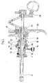
- the endoscopic instrument shown in FIG. 1 is a resectoscope with a distal-side hollow shaft 2, at the proximal end of which a connection part 4 is arranged.
- the connecting part 4 has both a line connection 6 for introducing a rinsing liquid into the hollow shaft 2 and a line connection 8 for sucking the rinsing liquid out of the hollow shaft 2.
- a slide valve 10 arranged in the connection part 4 either the line connection 6 or the line connection 8 can be closed or released. Closes in a middle position the slide valve 10, both the line connection 6 and the line connection 8.
- the slide valve 10 has a rotary valve 12 which is rotatable about a longitudinal axis of the hollow shaft 2 by means of a lever 14 that in a first position of the rotary valve 12 of the terminal. 6 released and the terminal 8 is closed and closed in a second position, the terminal 6 and the terminal 8 is released.
- a coupling part 16 connects to the connection part 4.
- this coupling part 16 is a known per se and therefore not described here in detail work insert 18, in which a not shown optics and an HF cutting sling are performed.
- the proximal end of the cutting loop is fixed in a lock body 24, which also carries the electrical connection contact 31.
- the lock body 24 handles 26 and 28, the cutting loop can be moved in the longitudinal direction.
- the coupling part 16 has a complementary to the contour of the working insert 18 opening 30.
- This aperture 30 has a distal-side opening 32 and a proximal-side opening 34, wherein the opening 34 is arranged eccentrically to the opening 32, that is, only the opening 32 is aligned with the shaft 2.
- a hollow-cylindrical projection 33 is formed at the front side of the essentially cylindrical coupling part 16, on which a shoulder 36 is provided.
- a sealing ring 38 is arranged so that it bears tightly against an end face formed by the shoulder 38 and on the peripheral surface formed by the shoulder.
- the sealing ring 38 is supported by the shoulder 36 both in the radial and in the axial direction and is thus connected in a rotationally fixed manner to the coupling part 16.
- a second shoulder 40 is formed on the outer circumference of the coupling part 16.
- a union nut 44 is rotatably mounted.
- the two-hole nut 42 has an internal thread with which it is screwed onto an external thread, which is arranged on a distal side of the shoulder 40 adjoining peripheral region of the coupling part 16. It has an end face on a stop ring, which is formed so that the union nut 44, when the two-nut 42 is screwed against the shoulder 40, is mounted both radially and axially with little play.
- the union nut 44 is rotatable relative to the coupling part 16 and forms both an axial and a radial bearing for the coupling part sixteenth
- the coupling part 16 with the connection part 4 is connectable.
- the connecting part 4 at its proximal end on the circumference of an external thread 46, on which the union nut 44 is screwed.
- an annular shoulder 48 is provided in order to deliver the coupling part 16 to the connection part 4 only so far that the coupling part 16 rests liquid-tight on the connection part 4, but the coupling part 16 remains rotatable relative to the connection part 4 and the shaft 2 arranged thereon, on the outer circumference of the connection part 4 on the distal side.
- the shoulder 48 forms a stop against which the union nut can be screwed to the external thread 46, so that the coupling part is freely rotatable.
- a coupling 52 is arranged on the proximal side, which serves for securing the working insert 18 in the coupling part 16.
- the clutch 52 is formed as known couplings of this type and therefore not described in detail here.
Landscapes
- Life Sciences & Earth Sciences (AREA)
- Health & Medical Sciences (AREA)
- Surgery (AREA)
- Engineering & Computer Science (AREA)
- Biophysics (AREA)
- Medical Informatics (AREA)
- Nuclear Medicine, Radiotherapy & Molecular Imaging (AREA)
- Optics & Photonics (AREA)
- Pathology (AREA)
- Radiology & Medical Imaging (AREA)
- Veterinary Medicine (AREA)
- Biomedical Technology (AREA)
- Heart & Thoracic Surgery (AREA)
- Physics & Mathematics (AREA)
- Molecular Biology (AREA)
- Animal Behavior & Ethology (AREA)
- General Health & Medical Sciences (AREA)
- Public Health (AREA)
- Mechanical Engineering (AREA)
- Endoscopes (AREA)
- Surgical Instruments (AREA)
Applications Claiming Priority (1)
| Application Number | Priority Date | Filing Date | Title |
|---|---|---|---|
| DE202004014828U DE202004014828U1 (de) | 2004-09-21 | 2004-09-21 | Endoskopisches Instrument |
Publications (2)
| Publication Number | Publication Date |
|---|---|
| EP1637065A1 true EP1637065A1 (fr) | 2006-03-22 |
| EP1637065B1 EP1637065B1 (fr) | 2012-04-11 |
Family
ID=33495460
Family Applications (1)
| Application Number | Title | Priority Date | Filing Date |
|---|---|---|---|
| EP05016840A Expired - Lifetime EP1637065B1 (fr) | 2004-09-21 | 2005-08-03 | Instrument endoscopique |
Country Status (4)
| Country | Link |
|---|---|
| US (1) | US8118729B2 (fr) |
| EP (1) | EP1637065B1 (fr) |
| AT (1) | ATE552769T1 (fr) |
| DE (1) | DE202004014828U1 (fr) |
Families Citing this family (11)
| Publication number | Priority date | Publication date | Assignee | Title |
|---|---|---|---|---|
| DE202004014828U1 (de) * | 2004-09-21 | 2004-12-02 | Richard Wolf Gmbh | Endoskopisches Instrument |
| US9504461B2 (en) * | 2005-05-20 | 2016-11-29 | Neotract, Inc. | Anchor delivery system |
| US7927271B2 (en) * | 2006-05-17 | 2011-04-19 | C.R. Bard, Inc. | Endoscope tool coupling |
| US7905882B1 (en) * | 2007-05-03 | 2011-03-15 | Ellman Alan G | Activator for electrosurgical handpiece |
| DE102008029301A1 (de) | 2008-06-19 | 2009-12-24 | Richard Wolf Gmbh | Endoskop- und Schaftsystem |
| US10271716B2 (en) | 2008-06-27 | 2019-04-30 | C.R. Bard, Inc. | Endoscopic vacuum controller |
| CN102905635B (zh) * | 2010-05-28 | 2015-09-09 | 捷锐士阿希迈公司 | 连续流动式内窥镜系统 |
| EP3190941A4 (fr) * | 2014-09-12 | 2017-09-13 | Massachusetts Institute of Technology | Instruments chirurgicaux ayant des poignées sélectivement rotatives |
| US10004385B2 (en) * | 2015-02-27 | 2018-06-26 | Covidien Lp | Oblique tip endoscope with zero degree field angle |
| EP4099887B1 (fr) * | 2020-02-04 | 2025-05-21 | Boston Scientific Scimed, Inc. | Dispositif médical rotatif |
| DE102023123938A1 (de) * | 2023-09-06 | 2025-03-06 | Karl Storz Se & Co. Kg | Dichtungsvorrichtung für ein chirurgisches Instrument und Verfahren |
Citations (7)
| Publication number | Priority date | Publication date | Assignee | Title |
|---|---|---|---|---|
| US5287845A (en) * | 1991-01-19 | 1994-02-22 | Olympus Winter & Ibe Gmbh | Endoscope for transurethral surgery |
| US5486155A (en) * | 1994-07-15 | 1996-01-23 | Circon Corporation | Rotatable endoscope sheath |
| DE19826311A1 (de) * | 1998-06-12 | 1999-12-23 | Bauer Und Haeselbarth Chirurg | Laserresektoskop |
| DE20004329U1 (de) * | 1999-03-10 | 2000-06-08 | Karl Storz GmbH & Co. KG, 78532 Tuttlingen | Rohrschaftsinstrument, insbesondere Proktoskop |
| US6358200B1 (en) * | 1999-09-01 | 2002-03-19 | Circon Corporation | Continuous flow resectoscope with single tube sheath assembly and rotatable connection |
| DE10138331A1 (de) * | 2001-07-27 | 2003-02-20 | Aesculap Ag & Co Kg | Endoskop |
| DE202004014828U1 (de) * | 2004-09-21 | 2004-12-02 | Richard Wolf Gmbh | Endoskopisches Instrument |
Family Cites Families (5)
| Publication number | Priority date | Publication date | Assignee | Title |
|---|---|---|---|---|
| DE7107645U (de) * | 1971-03-02 | 1971-05-27 | Storz K | Endoskop insbesondere cystoskop |
| US5435805A (en) | 1992-08-12 | 1995-07-25 | Vidamed, Inc. | Medical probe device with optical viewing capability |
| US5151101A (en) | 1988-06-02 | 1992-09-29 | Circon Corporation | System for disconnectably mounting an endoscope sheath with an endoscope tool |
| US6808505B2 (en) * | 2000-02-01 | 2004-10-26 | Kadan Jeffrey S | Diagnostic needle arthroscopy and lavage system |
| US20030050603A1 (en) * | 2001-09-12 | 2003-03-13 | Todd Erik F. | Cannula that provides bi-directional fluid flow that is regulated by a single valve |
-
2004
- 2004-09-21 DE DE202004014828U patent/DE202004014828U1/de not_active Expired - Lifetime
-
2005
- 2005-08-03 EP EP05016840A patent/EP1637065B1/fr not_active Expired - Lifetime
- 2005-08-03 AT AT05016840T patent/ATE552769T1/de active
- 2005-09-20 US US11/231,172 patent/US8118729B2/en active Active
Patent Citations (7)
| Publication number | Priority date | Publication date | Assignee | Title |
|---|---|---|---|---|
| US5287845A (en) * | 1991-01-19 | 1994-02-22 | Olympus Winter & Ibe Gmbh | Endoscope for transurethral surgery |
| US5486155A (en) * | 1994-07-15 | 1996-01-23 | Circon Corporation | Rotatable endoscope sheath |
| DE19826311A1 (de) * | 1998-06-12 | 1999-12-23 | Bauer Und Haeselbarth Chirurg | Laserresektoskop |
| DE20004329U1 (de) * | 1999-03-10 | 2000-06-08 | Karl Storz GmbH & Co. KG, 78532 Tuttlingen | Rohrschaftsinstrument, insbesondere Proktoskop |
| US6358200B1 (en) * | 1999-09-01 | 2002-03-19 | Circon Corporation | Continuous flow resectoscope with single tube sheath assembly and rotatable connection |
| DE10138331A1 (de) * | 2001-07-27 | 2003-02-20 | Aesculap Ag & Co Kg | Endoskop |
| DE202004014828U1 (de) * | 2004-09-21 | 2004-12-02 | Richard Wolf Gmbh | Endoskopisches Instrument |
Also Published As
| Publication number | Publication date |
|---|---|
| US20060063975A1 (en) | 2006-03-23 |
| US8118729B2 (en) | 2012-02-21 |
| DE202004014828U1 (de) | 2004-12-02 |
| EP1637065B1 (fr) | 2012-04-11 |
| ATE552769T1 (de) | 2012-04-15 |
Similar Documents
| Publication | Publication Date | Title |
|---|---|---|
| EP1523932B1 (fr) | Endoscope | |
| DE60130431T2 (de) | Rotierende fräswerkzeuge mit absaugkanälen aufweisende frässpitzen | |
| EP0496110B1 (fr) | Endoscope pour opération transurétrale | |
| EP0860148B1 (fr) | Attache de type à baionnette pour l'assemblage démontable de deux instruments tubulaires ou de deux pièces d'un instrument | |
| EP1325704B1 (fr) | Hystéroscope à tiges interchangeables | |
| EP0199848B1 (fr) | Dispositif pour introduire un endoscope ou un instrument chirurgical dans les organes creux avec des moyens pour alimenter et évacuer un liquide d'irrigation | |
| EP2135542B1 (fr) | Système d'endoscope et d'arbre | |
| DE19633124B4 (de) | Schab- bzw. Schneidinstrument | |
| WO1997018745A2 (fr) | Instrument de raclage et de coupe | |
| DE19819432C2 (de) | Handstück für ein medizinisches Gerät zum Saugen und Spülen | |
| EP1637065B1 (fr) | Instrument endoscopique | |
| EP2903494B1 (fr) | Système d'endoscopie et de biopsie à usage unique | |
| EP1234548B1 (fr) | Instrument de traitement médical ou dentaire avec un élément filtrant | |
| EP3015082B1 (fr) | Instrument medical demontable | |
| DE102021108314B4 (de) | Absperrhahn, Küken für einen Absperrhahn sowie Verfahren zur Herstellung eines Kükens für einen Absperrhahn | |
| DE10242608A1 (de) | Resektoskop mit abkuppelbarem Außenschaft | |
| DE69608975T2 (de) | Zwischenstück für dentales Handstück | |
| DE4402153C1 (de) | Spül- und Saugvorrichtung, insbesondere für die Chirurgie | |
| EP4151138B1 (fr) | Arbre externe pour un endoscope et système d'endoscopie | |
| DE3231693C2 (fr) | ||
| DE202024103652U1 (de) | Zerkleinerungsvorrichtung zur minimal-invasiven Zerkleinerung von Gewebe | |
| DE20112949U1 (de) | Endoskop | |
| DE19756629C2 (de) | Instrument, insbesondere Trokar oder Endoskop | |
| WO2026046551A1 (fr) | Système d'irrigation continue à usage médical | |
| DE102018121660B4 (de) | Endoskopanschlusskörper |
Legal Events
| Date | Code | Title | Description |
|---|---|---|---|
| PUAI | Public reference made under article 153(3) epc to a published international application that has entered the european phase |
Free format text: ORIGINAL CODE: 0009012 |
|
| AK | Designated contracting states |
Kind code of ref document: A1 Designated state(s): AT BE BG CH CY CZ DE DK EE ES FI FR GB GR HU IE IS IT LI LT LU LV MC NL PL PT RO SE SI SK TR |
|
| AX | Request for extension of the european patent |
Extension state: AL BA HR MK YU |
|
| 17P | Request for examination filed |
Effective date: 20060908 |
|
| 17Q | First examination report despatched |
Effective date: 20061019 |
|
| AKX | Designation fees paid |
Designated state(s): AT BE BG CH CY CZ DE DK EE ES FI FR GB GR HU IE IS IT LI LT LU LV MC NL PL PT RO SE SI SK TR |
|
| GRAP | Despatch of communication of intention to grant a patent |
Free format text: ORIGINAL CODE: EPIDOSNIGR1 |
|
| GRAS | Grant fee paid |
Free format text: ORIGINAL CODE: EPIDOSNIGR3 |
|
| GRAA | (expected) grant |
Free format text: ORIGINAL CODE: 0009210 |
|
| AK | Designated contracting states |
Kind code of ref document: B1 Designated state(s): AT BE BG CH CY CZ DE DK EE ES FI FR GB GR HU IE IS IT LI LT LU LV MC NL PL PT RO SE SI SK TR |
|
| REG | Reference to a national code |
Ref country code: GB Ref legal event code: FG4D Free format text: NOT ENGLISH |
|
| REG | Reference to a national code |
Ref country code: CH Ref legal event code: EP |
|
| REG | Reference to a national code |
Ref country code: AT Ref legal event code: REF Ref document number: 552769 Country of ref document: AT Kind code of ref document: T Effective date: 20120415 |
|
| REG | Reference to a national code |
Ref country code: IE Ref legal event code: FG4D Free format text: LANGUAGE OF EP DOCUMENT: GERMAN |
|
| REG | Reference to a national code |
Ref country code: DE Ref legal event code: R096 Ref document number: 502005012609 Country of ref document: DE Effective date: 20120606 |
|
| REG | Reference to a national code |
Ref country code: CH Ref legal event code: NV Representative=s name: ISLER & PEDRAZZINI AG |
|
| REG | Reference to a national code |
Ref country code: NL Ref legal event code: T3 |
|
| LTIE | Lt: invalidation of european patent or patent extension |
Effective date: 20120411 |
|
| PG25 | Lapsed in a contracting state [announced via postgrant information from national office to epo] |
Ref country code: LT Free format text: LAPSE BECAUSE OF FAILURE TO SUBMIT A TRANSLATION OF THE DESCRIPTION OR TO PAY THE FEE WITHIN THE PRESCRIBED TIME-LIMIT Effective date: 20120411 Ref country code: IS Free format text: LAPSE BECAUSE OF FAILURE TO SUBMIT A TRANSLATION OF THE DESCRIPTION OR TO PAY THE FEE WITHIN THE PRESCRIBED TIME-LIMIT Effective date: 20120811 Ref country code: PL Free format text: LAPSE BECAUSE OF FAILURE TO SUBMIT A TRANSLATION OF THE DESCRIPTION OR TO PAY THE FEE WITHIN THE PRESCRIBED TIME-LIMIT Effective date: 20120411 Ref country code: CY Free format text: LAPSE BECAUSE OF FAILURE TO SUBMIT A TRANSLATION OF THE DESCRIPTION OR TO PAY THE FEE WITHIN THE PRESCRIBED TIME-LIMIT Effective date: 20120411 Ref country code: FI Free format text: LAPSE BECAUSE OF FAILURE TO SUBMIT A TRANSLATION OF THE DESCRIPTION OR TO PAY THE FEE WITHIN THE PRESCRIBED TIME-LIMIT Effective date: 20120411 Ref country code: SE Free format text: LAPSE BECAUSE OF FAILURE TO SUBMIT A TRANSLATION OF THE DESCRIPTION OR TO PAY THE FEE WITHIN THE PRESCRIBED TIME-LIMIT Effective date: 20120411 |
|
| PG25 | Lapsed in a contracting state [announced via postgrant information from national office to epo] |
Ref country code: LV Free format text: LAPSE BECAUSE OF FAILURE TO SUBMIT A TRANSLATION OF THE DESCRIPTION OR TO PAY THE FEE WITHIN THE PRESCRIBED TIME-LIMIT Effective date: 20120411 Ref country code: PT Free format text: LAPSE BECAUSE OF FAILURE TO SUBMIT A TRANSLATION OF THE DESCRIPTION OR TO PAY THE FEE WITHIN THE PRESCRIBED TIME-LIMIT Effective date: 20120813 Ref country code: GR Free format text: LAPSE BECAUSE OF FAILURE TO SUBMIT A TRANSLATION OF THE DESCRIPTION OR TO PAY THE FEE WITHIN THE PRESCRIBED TIME-LIMIT Effective date: 20120712 Ref country code: SI Free format text: LAPSE BECAUSE OF FAILURE TO SUBMIT A TRANSLATION OF THE DESCRIPTION OR TO PAY THE FEE WITHIN THE PRESCRIBED TIME-LIMIT Effective date: 20120411 |
|
| PG25 | Lapsed in a contracting state [announced via postgrant information from national office to epo] |
Ref country code: SK Free format text: LAPSE BECAUSE OF FAILURE TO SUBMIT A TRANSLATION OF THE DESCRIPTION OR TO PAY THE FEE WITHIN THE PRESCRIBED TIME-LIMIT Effective date: 20120411 Ref country code: CZ Free format text: LAPSE BECAUSE OF FAILURE TO SUBMIT A TRANSLATION OF THE DESCRIPTION OR TO PAY THE FEE WITHIN THE PRESCRIBED TIME-LIMIT Effective date: 20120411 Ref country code: EE Free format text: LAPSE BECAUSE OF FAILURE TO SUBMIT A TRANSLATION OF THE DESCRIPTION OR TO PAY THE FEE WITHIN THE PRESCRIBED TIME-LIMIT Effective date: 20120411 Ref country code: DK Free format text: LAPSE BECAUSE OF FAILURE TO SUBMIT A TRANSLATION OF THE DESCRIPTION OR TO PAY THE FEE WITHIN THE PRESCRIBED TIME-LIMIT Effective date: 20120411 Ref country code: RO Free format text: LAPSE BECAUSE OF FAILURE TO SUBMIT A TRANSLATION OF THE DESCRIPTION OR TO PAY THE FEE WITHIN THE PRESCRIBED TIME-LIMIT Effective date: 20120411 |
|
| PLBE | No opposition filed within time limit |
Free format text: ORIGINAL CODE: 0009261 |
|
| STAA | Information on the status of an ep patent application or granted ep patent |
Free format text: STATUS: NO OPPOSITION FILED WITHIN TIME LIMIT |
|
| PG25 | Lapsed in a contracting state [announced via postgrant information from national office to epo] |
Ref country code: IT Free format text: LAPSE BECAUSE OF FAILURE TO SUBMIT A TRANSLATION OF THE DESCRIPTION OR TO PAY THE FEE WITHIN THE PRESCRIBED TIME-LIMIT Effective date: 20120411 |
|
| 26N | No opposition filed |
Effective date: 20130114 |
|
| PG25 | Lapsed in a contracting state [announced via postgrant information from national office to epo] |
Ref country code: MC Free format text: LAPSE BECAUSE OF NON-PAYMENT OF DUE FEES Effective date: 20120831 |
|
| PG25 | Lapsed in a contracting state [announced via postgrant information from national office to epo] |
Ref country code: ES Free format text: LAPSE BECAUSE OF FAILURE TO SUBMIT A TRANSLATION OF THE DESCRIPTION OR TO PAY THE FEE WITHIN THE PRESCRIBED TIME-LIMIT Effective date: 20120722 |
|
| REG | Reference to a national code |
Ref country code: DE Ref legal event code: R097 Ref document number: 502005012609 Country of ref document: DE Effective date: 20130114 |
|
| REG | Reference to a national code |
Ref country code: IE Ref legal event code: MM4A |
|
| PG25 | Lapsed in a contracting state [announced via postgrant information from national office to epo] |
Ref country code: BG Free format text: LAPSE BECAUSE OF FAILURE TO SUBMIT A TRANSLATION OF THE DESCRIPTION OR TO PAY THE FEE WITHIN THE PRESCRIBED TIME-LIMIT Effective date: 20120711 Ref country code: IE Free format text: LAPSE BECAUSE OF NON-PAYMENT OF DUE FEES Effective date: 20120803 |
|
| REG | Reference to a national code |
Ref country code: AT Ref legal event code: MM01 Ref document number: 552769 Country of ref document: AT Kind code of ref document: T Effective date: 20120831 |
|
| PG25 | Lapsed in a contracting state [announced via postgrant information from national office to epo] |
Ref country code: AT Free format text: LAPSE BECAUSE OF NON-PAYMENT OF DUE FEES Effective date: 20120831 |
|
| PG25 | Lapsed in a contracting state [announced via postgrant information from national office to epo] |
Ref country code: TR Free format text: LAPSE BECAUSE OF FAILURE TO SUBMIT A TRANSLATION OF THE DESCRIPTION OR TO PAY THE FEE WITHIN THE PRESCRIBED TIME-LIMIT Effective date: 20120411 |
|
| PG25 | Lapsed in a contracting state [announced via postgrant information from national office to epo] |
Ref country code: HU Free format text: LAPSE BECAUSE OF FAILURE TO SUBMIT A TRANSLATION OF THE DESCRIPTION OR TO PAY THE FEE WITHIN THE PRESCRIBED TIME-LIMIT Effective date: 20050803 |
|
| REG | Reference to a national code |
Ref country code: FR Ref legal event code: PLFP Year of fee payment: 12 |
|
| REG | Reference to a national code |
Ref country code: FR Ref legal event code: PLFP Year of fee payment: 13 |
|
| REG | Reference to a national code |
Ref country code: FR Ref legal event code: PLFP Year of fee payment: 14 |
|
| PGFP | Annual fee paid to national office [announced via postgrant information from national office to epo] |
Ref country code: NL Payment date: 20200819 Year of fee payment: 16 |
|
| PGFP | Annual fee paid to national office [announced via postgrant information from national office to epo] |
Ref country code: LU Payment date: 20200819 Year of fee payment: 16 Ref country code: GB Payment date: 20200824 Year of fee payment: 16 |
|
| PGFP | Annual fee paid to national office [announced via postgrant information from national office to epo] |
Ref country code: CH Payment date: 20200825 Year of fee payment: 16 Ref country code: BE Payment date: 20200818 Year of fee payment: 16 |
|
| REG | Reference to a national code |
Ref country code: DE Ref legal event code: R084 Ref document number: 502005012609 Country of ref document: DE |
|
| REG | Reference to a national code |
Ref country code: CH Ref legal event code: PL |
|
| REG | Reference to a national code |
Ref country code: NL Ref legal event code: MM Effective date: 20210901 |
|
| REG | Reference to a national code |
Ref country code: BE Ref legal event code: MM Effective date: 20210831 |
|
| GBPC | Gb: european patent ceased through non-payment of renewal fee |
Effective date: 20210803 |
|
| PG25 | Lapsed in a contracting state [announced via postgrant information from national office to epo] |
Ref country code: LI Free format text: LAPSE BECAUSE OF NON-PAYMENT OF DUE FEES Effective date: 20210831 Ref country code: CH Free format text: LAPSE BECAUSE OF NON-PAYMENT OF DUE FEES Effective date: 20210831 |
|
| PG25 | Lapsed in a contracting state [announced via postgrant information from national office to epo] |
Ref country code: LU Free format text: LAPSE BECAUSE OF NON-PAYMENT OF DUE FEES Effective date: 20210803 |
|
| PG25 | Lapsed in a contracting state [announced via postgrant information from national office to epo] |
Ref country code: NL Free format text: LAPSE BECAUSE OF NON-PAYMENT OF DUE FEES Effective date: 20210901 |
|
| PG25 | Lapsed in a contracting state [announced via postgrant information from national office to epo] |
Ref country code: GB Free format text: LAPSE BECAUSE OF NON-PAYMENT OF DUE FEES Effective date: 20210803 Ref country code: BE Free format text: LAPSE BECAUSE OF NON-PAYMENT OF DUE FEES Effective date: 20210831 |
|
| PGFP | Annual fee paid to national office [announced via postgrant information from national office to epo] |
Ref country code: FR Payment date: 20230821 Year of fee payment: 19 Ref country code: DE Payment date: 20230821 Year of fee payment: 19 |
|
| REG | Reference to a national code |
Ref country code: DE Ref legal event code: R119 Ref document number: 502005012609 Country of ref document: DE |
|
| PG25 | Lapsed in a contracting state [announced via postgrant information from national office to epo] |
Ref country code: DE Free format text: LAPSE BECAUSE OF NON-PAYMENT OF DUE FEES Effective date: 20250301 |
|
| PG25 | Lapsed in a contracting state [announced via postgrant information from national office to epo] |
Ref country code: FR Free format text: LAPSE BECAUSE OF NON-PAYMENT OF DUE FEES Effective date: 20240831 |