EP1637251A1 - Antrieb einer Drahtzuführeinheit für eine Federformmaschine - Google Patents
Antrieb einer Drahtzuführeinheit für eine Federformmaschine Download PDFInfo
- Publication number
- EP1637251A1 EP1637251A1 EP04022427A EP04022427A EP1637251A1 EP 1637251 A1 EP1637251 A1 EP 1637251A1 EP 04022427 A EP04022427 A EP 04022427A EP 04022427 A EP04022427 A EP 04022427A EP 1637251 A1 EP1637251 A1 EP 1637251A1
- Authority
- EP
- European Patent Office
- Prior art keywords
- wire feeder
- driving device
- manufacturing machine
- axial driving
- spring manufacturing
- Prior art date
- Legal status (The legal status is an assumption and is not a legal conclusion. Google has not performed a legal analysis and makes no representation as to the accuracy of the status listed.)
- Granted
Links
- 238000004519 manufacturing process Methods 0.000 title claims abstract description 56
- 230000007246 mechanism Effects 0.000 title claims abstract description 17
- 239000002184 metal Substances 0.000 abstract description 18
- 238000013459 approach Methods 0.000 abstract description 3
- 238000000034 method Methods 0.000 description 6
- 230000008569 process Effects 0.000 description 6
- 238000005452 bending Methods 0.000 description 3
- 238000006073 displacement reaction Methods 0.000 description 3
- 230000008859 change Effects 0.000 description 2
- 238000009434 installation Methods 0.000 description 2
- 238000012423 maintenance Methods 0.000 description 2
- 239000000463 material Substances 0.000 description 2
- 230000035939 shock Effects 0.000 description 2
- 238000004804 winding Methods 0.000 description 2
- 230000008901 benefit Effects 0.000 description 1
- 238000005520 cutting process Methods 0.000 description 1
- 230000007812 deficiency Effects 0.000 description 1
- 238000013461 design Methods 0.000 description 1
- 238000012545 processing Methods 0.000 description 1
- 239000002994 raw material Substances 0.000 description 1
Images


Classifications
-
- B—PERFORMING OPERATIONS; TRANSPORTING
- B21—MECHANICAL METAL-WORKING WITHOUT ESSENTIALLY REMOVING MATERIAL; PUNCHING METAL
- B21F—WORKING OR PROCESSING OF METAL WIRE
- B21F35/00—Making springs from wire
-
- B—PERFORMING OPERATIONS; TRANSPORTING
- B21—MECHANICAL METAL-WORKING WITHOUT ESSENTIALLY REMOVING MATERIAL; PUNCHING METAL
- B21F—WORKING OR PROCESSING OF METAL WIRE
- B21F23/00—Feeding wire in wire-working machines or apparatus
Definitions
- the present invention relates in general to a wire feeder driving mechanism for a spring manufacturing machine, and more particularly, to a mechanism which enables a spring manufacturing machine to simplify the actuating mechanism of its tool seat and thereby significantly cuts down the labor hours consumed for adjustment of the tool set of the spring manufacturing machine.
- the present invention enhances the easiness and the convenience of the operation of the spring manufacturing machine.
- springs are widely utilized in the shock absorbing or shock reducing, such as for automobiles, toys, electric appliances, switches, medical utilities, and so on, they have become an indispensable part of electric or mechanical equipments.
- the demand of spring shape becomes more and more versatile; it is therefore cannot be satisfied by a conventional spring manufacturing machine. Accordingly, to develop a next generation product to satisfy the strong demand of the market is an important issue for persons skilled in the spring manufacturing machine.
- a conventional spring manufacturing machine includes a machine base 10a and a work table 20a.
- the machine base 10a is secured thereon a wire feeder 11a which has a wire feeding chuck 12a at the front end thereof.
- the feeding chuck 12a is able to output the metal wire which will be formed into a spring.
- the work table 20a has a feeder hole 21a formed in the middle thereof which is able to receive the feeding chuck 12a.
- a plurality of tool seats 22a are installed on the work table 20a.
- Each tool seat 22a includes a driving rod 221a, a rail cam 222a, and a tool set 223a. By utilizing the driving rod 221a and the rail cam 222a, the tool set 223a is able to perform a linear or a curve motion for bending, winding, or cutting process of the metal wire.
- the conventional spring manufacturing machine has several radical problems.
- Third, to perform a curve motion of the tool set 223a it is conventional to further install a complicated or adjustable driving member.
- This auxiliary driving member not only raises the material and manufacture cost but also increases the difficulty of assembling and maintenance. Fourth, when various manufacture industries' demand for spring configuration becomes more and more complicated, the tool seats 22a installed on the work table 20a for convention are not sufficient. It is unable to satisfy modem manufacture industries' demand.
- the present invention provides a wire feeder driving mechanism for a spring manufacturing machine, which enables a wire feeder to perform a two-dimensional or a three-dimensional motion through installation of a two-dimensional driving device or a three-dimensional driving device.
- This invention successfully enables a spring manufacturing machine to simplify the actuating mechanism of its tool seat and thereby significantly cuts down the labor hours consumed for adjustment of the tool set of a spring manufacturing machine.
- the present invention enhances the easiness and the convenience of the operation and maintenance of a spring manufacturing machine.
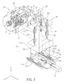
- the present invention provides a wire feeder driving mechanism for a spring manufacturing machine.
- This wire feeder driving mechanism includes a wire feeder 10, a first axial driving device 20, and a second axial driving device 30.
- a three dimensional Cartesian coordinate system is further designated in some figures.
- the wire feeder 10 includes a feeding box 11, a reeling motor 15, a feeding motor 16, a feeding chuck 18, and a spindle rotating motor 19.
- the feeding box 11 has a fixing platform 12 installed at one side thereof.
- a shaft mount 13 extends from the fixing platform 12.
- a shaft hole 14 is formed at the center of the shaft mount 13.
- the reeling motor 15 and the feeding motor 16 are connected to the rear of the feeding box 11.
- the reeling motor 15 rotates a metal wire reel in order to supply the wire feeder 10 with a metal wire.
- the feeding motor 16 feeds forward the metal wire through the rotating of a feed roller set 17.
- the feeding chuck 18 has a central hole which is utilized to receive and forward the metal wire.
- the spindle rotating motor 19 is able to drive and rotate the feeding chuck 18, which facilitates processing the metal wire at different angles.
- the first axial driving device 20 can be disposed parallel with the X axis, the Y axis, or the Z axis of the spring manufacturing machine. In the present embodiment the first driving device 20 is parallel with the Y axis of the spring manufacturing machine.
- the first axial driving device 20 includes a Y axis base body 21, a servo motor 22, a Y axis lead screw 23, and a flange mount 24.
- the Y axis base body 21 is constructed of a horizontal board 211 and a vertical frame 212, with a L-shaped configuration.
- a shaft mount 213 is formed at and extends from the middle of one side of the horizontal board 211.
- a shaft hole 214 is bored from the center of the shaft mount 213.
- the vertical frame 212 has parallel slide rails 215 installed at the both sides thereof.
- a plurality of slide blocks 216 are installed onto each slide rail 215.
- the slide block 216 is connected to the fixing platform 12 of the wire feeder 10.
- a fixed brace 217 is formed at and extends from the top of the vertical frame 212.
- the fixed brace 217 is utilized to install the servo motor 22.
- the servo motor 22 has a motor shaft which is oriented toward and coupled to the Y axis lead screw 23 through a shaft coupler or other mechanical elements.
- the Y axis lead screw 23 is oriented parallel with the moving direction of the slide rail 215.
- the flange mount 24 is screwed onto the Y axis lead screw 23 with one end thereof received by the shaft hole 14 of the feeding box 11 while the other end thereof secured on the shaft mount 13 of the feeding box 11 through bolts and nuts or other means.
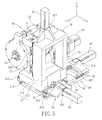
- the second axial driving device 30 can be disposed parallel with the X axis, the Y axis, or the Z axis of the spring manufacturing machine. In the present embodiment the second driving device 30 is parallel with the X axis of the spring manufacturing machine. The moving direction of the second axial driving device 30 is thereby perpendicular to that of the first axial driving device 20.
- the second axial driving device 30 is secured on the spring manufacturing machine through bolts and nuts or other mechanical elements, and further assembled with the first axial driving device 20 to enable the wire feeder 10 to perform a two dimensional planar movement.
- the second axial driving device 30 includes a X axis base body 31, a servo motor 32, a X axis lead screw 33, and a flange mount 34.
- the X axis base body 31 is secured on the spring manufacturing machine through a plurality of bolts and nuts or other means.
- a shaft mount 311 is formed at and extends from the middle of one side of X axis base body 31.
- a shaft hole 312 is bored from the center of the shaft mount 311.
- the X axis base body 31 has parallel slide rails 313 installed thereon which are perpendicular with the direction of the shaft hole 312.
- a plurality of slide blocks 314 are installed onto each slide rail 313.
- the horizontal board 211 of the Y axis base body 21 is placed onto and connected with the slide blocks 314.
- a fixed brace 315 is formed at and extends from one side of the X axis base body 31.
- the fixed brace 315 is utilized to install the servo motor 32.
- the servo motor 32 has a motor shaft which is oriented toward and coupled to the X axis lead screw 33 through a shaft coupler and other mechanical elements.
- the X axis lead screw 33 is disposed parallel with the moving direction of the slide rail 313.
- the flange mount 34 is screwed onto the X axis lead screw 33 with one end thereof received by the shaft hole 214 of the Y axis base body 21 while the other end thereof secured on the shaft mount 213 of the Y axis base body 21 through bolts or other means.
- another embodiment of the present invention further includes a third axial driving device 40 which is installed beneath the second axial driving device 30.
- the third axial driving device 40 can be disposed parallel with the X axis, the Y axis, or the Z axis of the spring manufacturing machine.
- the third axial driving device 40 is parallel with the Z axis of the spring manufacturing machine.
- the moving direction of the third axial driving device 40 is thereby perpendicular to those of the first and the second axial driving device 20, 30.
- the third axial driving device 40 is secured on the spring manufacturing machine through bolts and nuts or other means.
- the third axial driving device 40 is further assembled with the first and the second axial driving device 20, 30 to enable the wire feeder 10 to perform a three-dimensional movement.
- the third axial driving device 40 includes a Z axis base body 41, a servo motor 42, a Z axis lead screw 43, and a flange mount 44.
- the Z axis base body 41 has a plurality of through holes 411 formed thereon which are able to be inserted through by a plurality of bolts to secure the Z axis base body 41 onto the spring manufacturing machine, respectively.
- the Z axis base body 41 has parallel slide rails 412 installed on the top thereof. A plurality of slide blocks 413 are installed onto each slide rail 412.
- the X axis base body 31 is placed onto and connected with the slide blocks 413. Further, a fixed brace 414 is formed at and extends from one side of the Z axis base body 41. The fixed brace 414 is utilized to install the servo motor 42.
- the servo motor 42 has a motor shaft which is oriented toward and coupled to the Z axis lead screw 43 through a shaft coupler and other mechanical elements.
- the Z axis lead screw 43 is oriented parallel with the moving direction of the slide rail 412.
- the flange mount 44 is screwed onto the Z axis lead screw 43 with one end thereof received by the shaft hole 312 of the X axis base body 31 while the other end thereof secured on the shaft mount 311 of the X axis base body 31 through bolts or other means.
- a wire feeder 10 and a work table 52 are assembled onto the machine base 51 of the spring manufacturing machine 5.
- the spring manufacturing machine 5 has the machine base 51 installed parallel with the Z axis thereof which is perpendicular to the X-Y plane.
- the machine base 51 is a long rectangular prism in shape.
- the work table 52 is installed at the front end of the machine base 51, perpendicular to the machine base 51, and oriented parallel with the X-Y plane of the spring manufacturing machine 5.
- the work table 52 has a circular opening 53 formed in the middle thereof. Within the circular opening 53, the feeding chuck 18 of the wire feeder 10 is able to move upward, downward, left, right, forth, or backward, or move toward a combined direction which combines with the mentioned directions.
- the work table 52 has a plurality of tool seats 54 mounted thereon.
- a variety of tool sets 55 with different functions are respectively secured to each front end of the tool seats 54.
- the tool set 55 is capable of moving linearly relative to the tool seat 54 or rotating through the driving of a servo motor. The linear motion of the tool set 55 enables the tool secured thereon to enter or leave the inner of the circular opening 53.
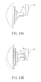
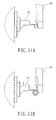
- a partial front view of a spring manufacturing machine illustrates the operation of the present invention.
- the tool set 55 is able to move linearly along the mounted direction of the tool seat 54 into the circular opening 53 of the work table 52.
- the axial driving devices 20, 30, 40 enable the wire feeder 10 to perform a desired displacement.
- the metal wire led by the feeding chuck 18 is thereby able to approach the tool set 55 through a two-dimensional or three-dimensional movement. Accordingly, the metal wire is capable of being manufactured into various spring final products with different complicated configurations.
- the spring manufacturing machine changes the position of the metal wire led by the feeding chuck 18 of the wire feeder 10 through the axial driving devices 20, 30, 40. Further utilizing the special shapes and structures of the tool set 55, the spring manufacturing machine is able to manufacture various springs with different shapes and styles. As illustrated in figure 9A and figure 9B, by the displacement of the feeding chuck 18 the metal wire is able to change its position relative to the tool set 55. Further accordingly changing the rotational direction of the tool set 55, the spring manufacturing machine is able to perform an upward curving or a downward curving.
- a wire feeder driving mechanism for a spring manufacturing machine in accordance with the present invention has at least four merits.
- First, the installation of the axial driving devices enable the feeding chuck of the wire feeder to perform a two-dimensional or three-dimensional approach to the tool set. This unique design exempts a spring manufacturing machine from using a complicated tool seat driving mechanism of a conventional art. The labor hours for adjustment of the tool set is thereby greatly cut down.
- Second, the movement of the tool set of the present invention is linear. It is easy to quantify the position point of the tool set. The replacement or adjustment of the tool set can be performed by an ordinary operator.
- Third, the displacement data of the axial driving devices is forward to the computer controller to automatically and precisely control the feeding chuck to perform a desired motion.
- the feeding chuck of the present invention is able to perform a three-dimensional motion, the usage of a tool set is more efficient than that of the prior art.
- the present invention therefore remedies the tool seat deficiency problem of the prior art.
Landscapes
- Engineering & Computer Science (AREA)
- Mechanical Engineering (AREA)
- Wire Processing (AREA)
- Springs (AREA)
Priority Applications (4)
| Application Number | Priority Date | Filing Date | Title |
|---|---|---|---|
| DE602004009928T DE602004009928T2 (de) | 2004-09-21 | 2004-09-21 | Federformmaschine mit einer Drahtzuführeinheit |
| PL04022427T PL1637251T3 (pl) | 2004-09-21 | 2004-09-21 | Maszyna do wytwarzania sprężyn zawierająca mechanizm napędowy podajnika drutu |
| EP04022427A EP1637251B1 (de) | 2004-09-21 | 2004-09-21 | Federformmaschine mit einer Drahtzuführeinheit |
| AT04022427T ATE377466T1 (de) | 2004-09-21 | 2004-09-21 | Federformmaschine mit einer drahtzuführeinheit |
Applications Claiming Priority (1)
| Application Number | Priority Date | Filing Date | Title |
|---|---|---|---|
| EP04022427A EP1637251B1 (de) | 2004-09-21 | 2004-09-21 | Federformmaschine mit einer Drahtzuführeinheit |
Publications (2)
| Publication Number | Publication Date |
|---|---|
| EP1637251A1 true EP1637251A1 (de) | 2006-03-22 |
| EP1637251B1 EP1637251B1 (de) | 2007-11-07 |
Family
ID=34926645
Family Applications (1)
| Application Number | Title | Priority Date | Filing Date |
|---|---|---|---|
| EP04022427A Expired - Lifetime EP1637251B1 (de) | 2004-09-21 | 2004-09-21 | Federformmaschine mit einer Drahtzuführeinheit |
Country Status (4)
| Country | Link |
|---|---|
| EP (1) | EP1637251B1 (de) |
| AT (1) | ATE377466T1 (de) |
| DE (1) | DE602004009928T2 (de) |
| PL (1) | PL1637251T3 (de) |
Cited By (5)
| Publication number | Priority date | Publication date | Assignee | Title |
|---|---|---|---|---|
| DE102007031514A1 (de) | 2007-07-06 | 2009-01-08 | Wafios Ag | Drahtverformungsmaschine |
| WO2012139932A3 (de) * | 2011-04-12 | 2012-12-20 | Wafios Ag | Verfahren und federmaschine zur herstellung von federn |
| CN106455332A (zh) * | 2016-11-15 | 2017-02-22 | 东莞东聚电子电讯制品有限公司 | 视觉自动折弯对位机构 |
| CN110227772A (zh) * | 2019-07-11 | 2019-09-13 | 李杭跃 | 长尾夹手柄制造机 |
| CN115582499A (zh) * | 2022-09-29 | 2023-01-10 | 厦门立洲五金弹簧有限公司 | 一种弧形弹簧的制作装置及方法 |
Citations (4)
| Publication number | Priority date | Publication date | Assignee | Title |
|---|---|---|---|---|
| EP0804978A1 (de) * | 1996-05-02 | 1997-11-05 | OMD OFFICINA MECCANICA DOMASO S.p.A. | Maschine zum Wickeln von Schraubenfedern mit Einfach- oder Doppelwindungen |
| US6151942A (en) * | 1998-08-21 | 2000-11-28 | Kabushiki Kaisha Itaya Seisaku Sho | Spring manufacturing apparatus |
| DE10100387A1 (de) * | 2001-01-05 | 2002-07-18 | Tang Well Tech Co | Kraftübertragungssteuersystem für eine Drahtformmaschine |
| US20040154365A1 (en) * | 2003-02-10 | 2004-08-12 | Katsuhide Tsuritani | Spring manufacturing machine |
-
2004
- 2004-09-21 EP EP04022427A patent/EP1637251B1/de not_active Expired - Lifetime
- 2004-09-21 DE DE602004009928T patent/DE602004009928T2/de not_active Expired - Lifetime
- 2004-09-21 AT AT04022427T patent/ATE377466T1/de not_active IP Right Cessation
- 2004-09-21 PL PL04022427T patent/PL1637251T3/pl unknown
Patent Citations (4)
| Publication number | Priority date | Publication date | Assignee | Title |
|---|---|---|---|---|
| EP0804978A1 (de) * | 1996-05-02 | 1997-11-05 | OMD OFFICINA MECCANICA DOMASO S.p.A. | Maschine zum Wickeln von Schraubenfedern mit Einfach- oder Doppelwindungen |
| US6151942A (en) * | 1998-08-21 | 2000-11-28 | Kabushiki Kaisha Itaya Seisaku Sho | Spring manufacturing apparatus |
| DE10100387A1 (de) * | 2001-01-05 | 2002-07-18 | Tang Well Tech Co | Kraftübertragungssteuersystem für eine Drahtformmaschine |
| US20040154365A1 (en) * | 2003-02-10 | 2004-08-12 | Katsuhide Tsuritani | Spring manufacturing machine |
Cited By (11)
| Publication number | Priority date | Publication date | Assignee | Title |
|---|---|---|---|---|
| DE102007031514A1 (de) | 2007-07-06 | 2009-01-08 | Wafios Ag | Drahtverformungsmaschine |
| US8166786B2 (en) | 2007-07-06 | 2012-05-01 | Wafios Aktiengesellschaft | Wire-forming machine |
| WO2012139932A3 (de) * | 2011-04-12 | 2012-12-20 | Wafios Ag | Verfahren und federmaschine zur herstellung von federn |
| CN103781570A (zh) * | 2011-04-12 | 2014-05-07 | 瓦菲奥斯股份公司 | 用于制造弹簧的方法和弹簧机 |
| US9370817B2 (en) | 2011-04-12 | 2016-06-21 | Wafios Ag | Method and system for programming the control of a multiaxis forming machine and forming machine |
| TWI625177B (zh) * | 2011-04-12 | 2018-06-01 | 瓦菲思公司 | 彈簧製造方法及執行此方法的彈簧機 |
| CN106455332A (zh) * | 2016-11-15 | 2017-02-22 | 东莞东聚电子电讯制品有限公司 | 视觉自动折弯对位机构 |
| CN106455332B (zh) * | 2016-11-15 | 2018-12-04 | 东莞东聚电子电讯制品有限公司 | 视觉自动折弯对位机构 |
| CN110227772A (zh) * | 2019-07-11 | 2019-09-13 | 李杭跃 | 长尾夹手柄制造机 |
| CN110227772B (zh) * | 2019-07-11 | 2024-01-30 | 陶永亮 | 长尾夹手柄制造机 |
| CN115582499A (zh) * | 2022-09-29 | 2023-01-10 | 厦门立洲五金弹簧有限公司 | 一种弧形弹簧的制作装置及方法 |
Also Published As
| Publication number | Publication date |
|---|---|
| DE602004009928D1 (de) | 2007-12-20 |
| DE602004009928T2 (de) | 2008-08-21 |
| EP1637251B1 (de) | 2007-11-07 |
| PL1637251T3 (pl) | 2008-03-31 |
| ATE377466T1 (de) | 2007-11-15 |
Similar Documents
| Publication | Publication Date | Title |
|---|---|---|
| US7134305B2 (en) | Wire feeder driving mechanism for spring manufacturing machine | |
| TWI337903B (en) | Wire-forming machine | |
| EP3195952B1 (de) | Omnidirektionaler manipulator zur verwendung mit federformmaschine | |
| US20140165348A1 (en) | Machine tool with lathe tool and milling cutter | |
| US20120107064A1 (en) | CNC Machine Tool Having Two Spindles | |
| JPH08174120A (ja) | 線材成形装置 | |
| JP5798162B2 (ja) | ワイヤ成形装置 | |
| US20140020527A1 (en) | Machine tool with uninterrupted cutting | |
| EP1637251B1 (de) | Federformmaschine mit einer Drahtzuführeinheit | |
| JP5325369B2 (ja) | ばね製造機 | |
| US8336353B2 (en) | Coil spring manufacturing machine | |
| CN116351989B (zh) | 线材用送料装置 | |
| US6571591B2 (en) | Spring manufacturing apparatus and wire guide used for the same | |
| KR20180130986A (ko) | 공작 기계의 이송장치 | |
| CN110814213B (zh) | 一种五轴弯线机 | |
| JP4336637B2 (ja) | ばね製造装置におけるワイヤフィーダ駆動機構 | |
| CN203956649U (zh) | 数控刀片磨削设备 | |
| JP5371212B2 (ja) | ばね製造機 | |
| KR200370821Y1 (ko) | 스프링 제조 장치용 와이어 공급기 구동 메카니즘 | |
| CN111790780B (zh) | 一种薄铁皮异形件连续折弯机 | |
| CN111673009B (zh) | 一种数控弹簧成型机3d成型结构 | |
| JP5366143B2 (ja) | コイルばね製造装置及びコイルばね製造方法 | |
| CN112719128B (zh) | 一种线材自由弯曲成形设备 | |
| US9238306B2 (en) | Feeding device and machine tool using the same | |
| CN116353081B (zh) | 椅子坐垫的组装方法和设备 |
Legal Events
| Date | Code | Title | Description |
|---|---|---|---|
| PUAI | Public reference made under article 153(3) epc to a published international application that has entered the european phase |
Free format text: ORIGINAL CODE: 0009012 |
|
| 17P | Request for examination filed |
Effective date: 20050707 |
|
| AK | Designated contracting states |
Kind code of ref document: A1 Designated state(s): AT BE BG CH CY CZ DE DK EE ES FI FR GB GR HU IE IT LI LU MC NL PL PT RO SE SI SK TR |
|
| AX | Request for extension of the european patent |
Extension state: AL HR LT LV MK |
|
| 17Q | First examination report despatched |
Effective date: 20060201 |
|
| AKX | Designation fees paid |
Designated state(s): AT BE BG CH CY CZ DE DK EE ES FI FR GB GR HU IE IT LI LU MC NL PL PT RO SE SI SK TR |
|
| GRAP | Despatch of communication of intention to grant a patent |
Free format text: ORIGINAL CODE: EPIDOSNIGR1 |
|
| RTI1 | Title (correction) |
Free format text: SPRING MANUFACTURING MACHINE COMPRISING A WIRE FEEDER DRIVING MECHANISM |
|
| GRAS | Grant fee paid |
Free format text: ORIGINAL CODE: EPIDOSNIGR3 |
|
| GRAA | (expected) grant |
Free format text: ORIGINAL CODE: 0009210 |
|
| AK | Designated contracting states |
Kind code of ref document: B1 Designated state(s): AT BE BG CH CY CZ DE DK EE ES FI FR GB GR HU IE IT LI LU MC NL PL PT RO SE SI SK TR |
|
| REG | Reference to a national code |
Ref country code: GB Ref legal event code: FG4D |
|
| REG | Reference to a national code |
Ref country code: IE Ref legal event code: FG4D |
|
| REG | Reference to a national code |
Ref country code: CH Ref legal event code: EP |
|
| REF | Corresponds to: |
Ref document number: 602004009928 Country of ref document: DE Date of ref document: 20071220 Kind code of ref document: P |
|
| REG | Reference to a national code |
Ref country code: PL Ref legal event code: T3 |
|
| PG25 | Lapsed in a contracting state [announced via postgrant information from national office to epo] |
Ref country code: LI Free format text: LAPSE BECAUSE OF FAILURE TO SUBMIT A TRANSLATION OF THE DESCRIPTION OR TO PAY THE FEE WITHIN THE PRESCRIBED TIME-LIMIT Effective date: 20071107 Ref country code: SE Free format text: LAPSE BECAUSE OF FAILURE TO SUBMIT A TRANSLATION OF THE DESCRIPTION OR TO PAY THE FEE WITHIN THE PRESCRIBED TIME-LIMIT Effective date: 20080207 Ref country code: NL Free format text: LAPSE BECAUSE OF FAILURE TO SUBMIT A TRANSLATION OF THE DESCRIPTION OR TO PAY THE FEE WITHIN THE PRESCRIBED TIME-LIMIT Effective date: 20071107 Ref country code: ES Free format text: LAPSE BECAUSE OF FAILURE TO SUBMIT A TRANSLATION OF THE DESCRIPTION OR TO PAY THE FEE WITHIN THE PRESCRIBED TIME-LIMIT Effective date: 20080218 Ref country code: CH Free format text: LAPSE BECAUSE OF FAILURE TO SUBMIT A TRANSLATION OF THE DESCRIPTION OR TO PAY THE FEE WITHIN THE PRESCRIBED TIME-LIMIT Effective date: 20071107 |
|
| NLV1 | Nl: lapsed or annulled due to failure to fulfill the requirements of art. 29p and 29m of the patents act | ||
| PG25 | Lapsed in a contracting state [announced via postgrant information from national office to epo] |
Ref country code: SI Free format text: LAPSE BECAUSE OF FAILURE TO SUBMIT A TRANSLATION OF THE DESCRIPTION OR TO PAY THE FEE WITHIN THE PRESCRIBED TIME-LIMIT Effective date: 20071107 Ref country code: BG Free format text: LAPSE BECAUSE OF FAILURE TO SUBMIT A TRANSLATION OF THE DESCRIPTION OR TO PAY THE FEE WITHIN THE PRESCRIBED TIME-LIMIT Effective date: 20080207 |
|
| REG | Reference to a national code |
Ref country code: CH Ref legal event code: PL |
|
| ET | Fr: translation filed | ||
| PG25 | Lapsed in a contracting state [announced via postgrant information from national office to epo] |
Ref country code: AT Free format text: LAPSE BECAUSE OF FAILURE TO SUBMIT A TRANSLATION OF THE DESCRIPTION OR TO PAY THE FEE WITHIN THE PRESCRIBED TIME-LIMIT Effective date: 20071107 |
|
| PG25 | Lapsed in a contracting state [announced via postgrant information from national office to epo] |
Ref country code: DK Free format text: LAPSE BECAUSE OF FAILURE TO SUBMIT A TRANSLATION OF THE DESCRIPTION OR TO PAY THE FEE WITHIN THE PRESCRIBED TIME-LIMIT Effective date: 20071107 |
|
| PG25 | Lapsed in a contracting state [announced via postgrant information from national office to epo] |
Ref country code: RO Free format text: LAPSE BECAUSE OF FAILURE TO SUBMIT A TRANSLATION OF THE DESCRIPTION OR TO PAY THE FEE WITHIN THE PRESCRIBED TIME-LIMIT Effective date: 20071107 Ref country code: SK Free format text: LAPSE BECAUSE OF FAILURE TO SUBMIT A TRANSLATION OF THE DESCRIPTION OR TO PAY THE FEE WITHIN THE PRESCRIBED TIME-LIMIT Effective date: 20071107 |
|
| PLBE | No opposition filed within time limit |
Free format text: ORIGINAL CODE: 0009261 |
|
| STAA | Information on the status of an ep patent application or granted ep patent |
Free format text: STATUS: NO OPPOSITION FILED WITHIN TIME LIMIT |
|
| PG25 | Lapsed in a contracting state [announced via postgrant information from national office to epo] |
Ref country code: PT Free format text: LAPSE BECAUSE OF FAILURE TO SUBMIT A TRANSLATION OF THE DESCRIPTION OR TO PAY THE FEE WITHIN THE PRESCRIBED TIME-LIMIT Effective date: 20080407 |
|
| 26N | No opposition filed |
Effective date: 20080808 |
|
| PG25 | Lapsed in a contracting state [announced via postgrant information from national office to epo] |
Ref country code: GR Free format text: LAPSE BECAUSE OF FAILURE TO SUBMIT A TRANSLATION OF THE DESCRIPTION OR TO PAY THE FEE WITHIN THE PRESCRIBED TIME-LIMIT Effective date: 20080208 |
|
| PG25 | Lapsed in a contracting state [announced via postgrant information from national office to epo] |
Ref country code: FI Free format text: LAPSE BECAUSE OF FAILURE TO SUBMIT A TRANSLATION OF THE DESCRIPTION OR TO PAY THE FEE WITHIN THE PRESCRIBED TIME-LIMIT Effective date: 20071107 |
|
| PG25 | Lapsed in a contracting state [announced via postgrant information from national office to epo] |
Ref country code: EE Free format text: LAPSE BECAUSE OF FAILURE TO SUBMIT A TRANSLATION OF THE DESCRIPTION OR TO PAY THE FEE WITHIN THE PRESCRIBED TIME-LIMIT Effective date: 20071107 Ref country code: MC Free format text: LAPSE BECAUSE OF NON-PAYMENT OF DUE FEES Effective date: 20080930 |
|
| PG25 | Lapsed in a contracting state [announced via postgrant information from national office to epo] |
Ref country code: IE Free format text: LAPSE BECAUSE OF NON-PAYMENT OF DUE FEES Effective date: 20080922 Ref country code: CY Free format text: LAPSE BECAUSE OF FAILURE TO SUBMIT A TRANSLATION OF THE DESCRIPTION OR TO PAY THE FEE WITHIN THE PRESCRIBED TIME-LIMIT Effective date: 20071107 |
|
| PG25 | Lapsed in a contracting state [announced via postgrant information from national office to epo] |
Ref country code: LU Free format text: LAPSE BECAUSE OF NON-PAYMENT OF DUE FEES Effective date: 20080921 Ref country code: HU Free format text: LAPSE BECAUSE OF FAILURE TO SUBMIT A TRANSLATION OF THE DESCRIPTION OR TO PAY THE FEE WITHIN THE PRESCRIBED TIME-LIMIT Effective date: 20080508 |
|
| PGFP | Annual fee paid to national office [announced via postgrant information from national office to epo] |
Ref country code: TR Payment date: 20140912 Year of fee payment: 11 |
|
| REG | Reference to a national code |
Ref country code: FR Ref legal event code: PLFP Year of fee payment: 12 |
|
| PGFP | Annual fee paid to national office [announced via postgrant information from national office to epo] |
Ref country code: CZ Payment date: 20150917 Year of fee payment: 12 |
|
| PGFP | Annual fee paid to national office [announced via postgrant information from national office to epo] |
Ref country code: BE Payment date: 20150921 Year of fee payment: 12 Ref country code: FR Payment date: 20150916 Year of fee payment: 12 Ref country code: PL Payment date: 20150910 Year of fee payment: 12 |
|
| PGFP | Annual fee paid to national office [announced via postgrant information from national office to epo] |
Ref country code: GB Payment date: 20160914 Year of fee payment: 13 Ref country code: DE Payment date: 20160926 Year of fee payment: 13 |
|
| PG25 | Lapsed in a contracting state [announced via postgrant information from national office to epo] |
Ref country code: BE Free format text: LAPSE BECAUSE OF NON-PAYMENT OF DUE FEES Effective date: 20160930 |
|
| PGFP | Annual fee paid to national office [announced via postgrant information from national office to epo] |
Ref country code: IT Payment date: 20160927 Year of fee payment: 13 |
|
| PG25 | Lapsed in a contracting state [announced via postgrant information from national office to epo] |
Ref country code: CZ Free format text: LAPSE BECAUSE OF NON-PAYMENT OF DUE FEES Effective date: 20160921 |
|
| REG | Reference to a national code |
Ref country code: FR Ref legal event code: ST Effective date: 20170531 |
|
| PG25 | Lapsed in a contracting state [announced via postgrant information from national office to epo] |
Ref country code: FR Free format text: LAPSE BECAUSE OF NON-PAYMENT OF DUE FEES Effective date: 20160930 |
|
| REG | Reference to a national code |
Ref country code: BE Ref legal event code: MM Effective date: 20160930 |
|
| PG25 | Lapsed in a contracting state [announced via postgrant information from national office to epo] |
Ref country code: PL Free format text: LAPSE BECAUSE OF NON-PAYMENT OF DUE FEES Effective date: 20160921 |
|
| REG | Reference to a national code |
Ref country code: DE Ref legal event code: R119 Ref document number: 602004009928 Country of ref document: DE |
|
| GBPC | Gb: european patent ceased through non-payment of renewal fee |
Effective date: 20170921 |
|
| PG25 | Lapsed in a contracting state [announced via postgrant information from national office to epo] |
Ref country code: DE Free format text: LAPSE BECAUSE OF NON-PAYMENT OF DUE FEES Effective date: 20180404 Ref country code: GB Free format text: LAPSE BECAUSE OF NON-PAYMENT OF DUE FEES Effective date: 20170921 |
|
| PG25 | Lapsed in a contracting state [announced via postgrant information from national office to epo] |
Ref country code: IT Free format text: LAPSE BECAUSE OF NON-PAYMENT OF DUE FEES Effective date: 20170921 |
|
| PG25 | Lapsed in a contracting state [announced via postgrant information from national office to epo] |
Ref country code: TR Free format text: LAPSE BECAUSE OF NON-PAYMENT OF DUE FEES Effective date: 20160921 |