EP1637252B1 - Dispositif de lubrification et de refroidissement des formes, en particulier matrices et outils de forgeage dans la technique de formage - Google Patents
Dispositif de lubrification et de refroidissement des formes, en particulier matrices et outils de forgeage dans la technique de formage Download PDFInfo
- Publication number
- EP1637252B1 EP1637252B1 EP04022305A EP04022305A EP1637252B1 EP 1637252 B1 EP1637252 B1 EP 1637252B1 EP 04022305 A EP04022305 A EP 04022305A EP 04022305 A EP04022305 A EP 04022305A EP 1637252 B1 EP1637252 B1 EP 1637252B1
- Authority
- EP
- European Patent Office
- Prior art keywords
- lubricant
- coolant
- channels
- flow channels
- nozzles
- Prior art date
- Legal status (The legal status is an assumption and is not a legal conclusion. Google has not performed a legal analysis and makes no representation as to the accuracy of the status listed.)
- Expired - Lifetime
Links
- 238000001816 cooling Methods 0.000 title claims description 7
- 238000005242 forging Methods 0.000 title claims description 7
- 238000005461 lubrication Methods 0.000 title claims description 6
- 239000002184 metal Substances 0.000 title claims 2
- 239000000314 lubricant Substances 0.000 claims abstract description 47
- 239000002826 coolant Substances 0.000 claims abstract description 35
- 238000005507 spraying Methods 0.000 claims description 19
- 238000007789 sealing Methods 0.000 claims description 4
- 238000007599 discharging Methods 0.000 claims 2
- 239000007921 spray Substances 0.000 abstract description 35
- 239000000110 cooling liquid Substances 0.000 description 5
- 238000000034 method Methods 0.000 description 4
- 239000000203 mixture Substances 0.000 description 4
- 230000001050 lubricating effect Effects 0.000 description 3
- XLYOFNOQVPJJNP-UHFFFAOYSA-N water Substances O XLYOFNOQVPJJNP-UHFFFAOYSA-N 0.000 description 3
- 238000010276 construction Methods 0.000 description 2
- 239000010687 lubricating oil Substances 0.000 description 2
- 239000003570 air Substances 0.000 description 1
- 238000000889 atomisation Methods 0.000 description 1
- 238000007664 blowing Methods 0.000 description 1
- 238000004891 communication Methods 0.000 description 1
- 238000011144 upstream manufacturing Methods 0.000 description 1
Images



Classifications
-
- B—PERFORMING OPERATIONS; TRANSPORTING
- B05—SPRAYING OR ATOMISING IN GENERAL; APPLYING FLUENT MATERIALS TO SURFACES, IN GENERAL
- B05B—SPRAYING APPARATUS; ATOMISING APPARATUS; NOZZLES
- B05B1/00—Nozzles, spray heads or other outlets, with or without auxiliary devices such as valves, heating means
- B05B1/34—Nozzles, spray heads or other outlets, with or without auxiliary devices such as valves, heating means designed to influence the nature of flow of the liquid or other fluent material, e.g. to produce swirl
- B05B1/3405—Nozzles, spray heads or other outlets, with or without auxiliary devices such as valves, heating means designed to influence the nature of flow of the liquid or other fluent material, e.g. to produce swirl to produce swirl
- B05B1/341—Nozzles, spray heads or other outlets, with or without auxiliary devices such as valves, heating means designed to influence the nature of flow of the liquid or other fluent material, e.g. to produce swirl to produce swirl before discharging the liquid or other fluent material, e.g. in a swirl chamber upstream the spray outlet
- B05B1/3421—Nozzles, spray heads or other outlets, with or without auxiliary devices such as valves, heating means designed to influence the nature of flow of the liquid or other fluent material, e.g. to produce swirl to produce swirl before discharging the liquid or other fluent material, e.g. in a swirl chamber upstream the spray outlet with channels emerging substantially tangentially in the swirl chamber
- B05B1/3431—Nozzles, spray heads or other outlets, with or without auxiliary devices such as valves, heating means designed to influence the nature of flow of the liquid or other fluent material, e.g. to produce swirl to produce swirl before discharging the liquid or other fluent material, e.g. in a swirl chamber upstream the spray outlet with channels emerging substantially tangentially in the swirl chamber the channels being formed at the interface of cooperating elements, e.g. by means of grooves
- B05B1/3442—Nozzles, spray heads or other outlets, with or without auxiliary devices such as valves, heating means designed to influence the nature of flow of the liquid or other fluent material, e.g. to produce swirl to produce swirl before discharging the liquid or other fluent material, e.g. in a swirl chamber upstream the spray outlet with channels emerging substantially tangentially in the swirl chamber the channels being formed at the interface of cooperating elements, e.g. by means of grooves the interface being a cone having the same axis as the outlet
-
- B—PERFORMING OPERATIONS; TRANSPORTING
- B05—SPRAYING OR ATOMISING IN GENERAL; APPLYING FLUENT MATERIALS TO SURFACES, IN GENERAL
- B05B—SPRAYING APPARATUS; ATOMISING APPARATUS; NOZZLES
- B05B1/00—Nozzles, spray heads or other outlets, with or without auxiliary devices such as valves, heating means
- B05B1/14—Nozzles, spray heads or other outlets, with or without auxiliary devices such as valves, heating means with multiple outlet openings; with strainers in or outside the outlet opening
-
- B—PERFORMING OPERATIONS; TRANSPORTING
- B05—SPRAYING OR ATOMISING IN GENERAL; APPLYING FLUENT MATERIALS TO SURFACES, IN GENERAL
- B05B—SPRAYING APPARATUS; ATOMISING APPARATUS; NOZZLES
- B05B7/00—Spraying apparatus for discharge of liquids or other fluent materials from two or more sources, e.g. of liquid and air, of powder and gas
- B05B7/02—Spray pistols; Apparatus for discharge
- B05B7/08—Spray pistols; Apparatus for discharge with separate outlet orifices, e.g. to form parallel jets, i.e. the axis of the jets being parallel, to form intersecting jets, i.e. the axis of the jets converging but not necessarily intersecting at a point
- B05B7/0892—Spray pistols; Apparatus for discharge with separate outlet orifices, e.g. to form parallel jets, i.e. the axis of the jets being parallel, to form intersecting jets, i.e. the axis of the jets converging but not necessarily intersecting at a point the outlet orifices for jets constituted by a liquid or a mixture containing a liquid being disposed on a circle
-
- B—PERFORMING OPERATIONS; TRANSPORTING
- B21—MECHANICAL METAL-WORKING WITHOUT ESSENTIALLY REMOVING MATERIAL; PUNCHING METAL
- B21J—FORGING; HAMMERING; PRESSING METAL; RIVETING; FORGE FURNACES
- B21J1/00—Preparing metal stock or similar ancillary operations prior, during or post forging, e.g. heating or cooling
- B21J1/06—Heating or cooling methods or arrangements specially adapted for performing forging or pressing operations
-
- B—PERFORMING OPERATIONS; TRANSPORTING
- B21—MECHANICAL METAL-WORKING WITHOUT ESSENTIALLY REMOVING MATERIAL; PUNCHING METAL
- B21J—FORGING; HAMMERING; PRESSING METAL; RIVETING; FORGE FURNACES
- B21J3/00—Lubricating during forging or pressing
Definitions
- the invention relates to a device for lubricating and cooling of molds, in particular of forging dies and tools in the forming technique, with flow channels for supplying a lubricant and a coolant and with nozzles for spraying the lubricant and the coolant, wherein the flow channels for lubricant and coolant separated from each other are and wherein the lubricant flow channels for spraying the lubricant designed nozzles and the coolant flow channels for spraying the coolant designed nozzles are assigned, according to the preamble of claim 1.
- Disk spray heads are known (EP-PS 0 724 486 ), by assembling the outer shape of the mold of the die can be adapted and in a gravure facing plate bores for the application of a mixture consisting of a lubricant and water, have.
- Such spray heads are relatively expensive and have the disadvantage that the lubricant water mixture can not be sprayed optimally, so that the lubricant consumption is relatively high.
- Pneumatic atomizing nozzles are also known, which are guided by an industrial robot and start the engraving of the die in tracks and spray with a lubricant water mixture.
- Spray elements in particular for molds that produce and release a lubricant / coolant mixture are, for example, from DE 44 20 679 A1 known.
- the effort to handle such Einzelsprühdüsen is very large.
- a device for lubricating and cooling forging dies in which the flow channels for lubricant and coolant are separated from each other and associated with the lubricant flow channels for spraying the lubricant nozzles and the coolant flow channels designed for spraying the coolant nozzles.
- Lubricant piping and coolant piping are arranged on a support arm. Respectively assigned spray nozzles are activated when the holding arm advances in the direction of the workpieces when the forging dies are opened.
- a forming machine is provided with lubricating and cooling devices, are provided in the separate exhaust nozzles for blowing out a die and lubricant nozzles for applying lubricant.
- the exhaust nozzles and the lubricant nozzles are at the end of separate Pipes arranged, which in turn are connected to a Manipulierarm. The manipulation arm travels between the upper die and the lower die, and then the exhaust nozzle and the lubricant nozzle are activated.
- the invention has for its object to provide a simplification of such lubrication and cooling devices.
- a device of the type mentioned that the flow channels for the lubricant and for the coolant in a common housing, ie in a single spray head, are laid, said housing is attached to guide arms in a conventional manner which are movable into the open molds or dies, and that the housing is provided with a central chamber and at least one lid which covers the chamber and has flow channels, in particular annular channels, separate from the chamber with at least one of the ones for the spraying operation required medium are applied.
- the spray nozzles for coolant on the one hand and for the lubricant can now be optimally designed on the other hand, and it can be provided, for example, so-called minimal lubrication nozzles for spraying the lubricant, so that the consumption of lubricant can be significantly reduced.
- the coolant consumption because here too can be used for spraying the coolant optimal nozzle types. Separate guidance of coolant or lubricant nozzles is therefore superfluous. It is also achieved a compact and relatively simple design of a spray head.
- the flow channels in the cover can be designed as ring channels, which come from outside feed channels are loaded with a medium required for the spraying process.
- These feed channels can advantageously open radially into the annular channels.
- the central chamber is expediently provided with a radially opening feed channel for the coolant and closed by a circular cover disc, which is equipped with coolant nozzles, which are arranged to several evenly distributed over a diameter of the cover disc.
- This cover plate can be screwed in a simple manner in a cover ring and completed by a gasket to the central chamber out. This results in a simple construction of the spray device.
- each coolant nozzle can be preceded by a swirl insert, wherein these swirl inserts can be screwed into threaded bores which are provided on the side facing the central chamber side of the coolant nozzle bores.
- the annular channels can be provided in the surrounding region of the central chamber of the housing as circumferential grooves, which are completed by a cover ring comprising the cover ring into which the cover plate is also screwed.
- the outer annular channel may be connected to a supply channel for lubricant, the inner annular channel with a compressed air supply.
- Schmierstoffsprühdüsen in particular in the form of minimal lubrication nozzles, may be provided in the cover ring, which are each connected to branch channels for compressed air supply, leading to the inner ring channel.
- branch channels in turn, can be designed in a simple manner as transverse bores, which open into the core hole of the fastening thread for the lubricant spray nozzles.
- the supply channels for compressed air, lubricant and coolant can be laid parallel to each other in a serving as a guide arm connecting piece through which the device according to the invention, i. that is, the spray head according to the invention, can be introduced into the forging die or in the tool.
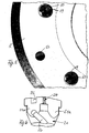
- the Fig. 1 to 4 show a cylindrical housing 1 in the form of a one-sided open shell, which is provided on one side with a flat flattening 2, which is parallel to the central axis 3 of the housing first runs.
- the central chamber 4 of the housing 1 is completed on the side of fenen of a lid which consists of a cover ring 5 with a lateral flattening 2 flattening and from a screwed-in cover plate 6, in a thread 7 of the cover ring. 5 is screwed and is provided for the assembly process with lateral parallel attack surfaces 8 for a tool.
- the countersunk screws 9 hold the cover ring 5 on the housing. 1
- the flattening 2 is provided in the region of the housing 1 with connections for the media to be sprayed and there is provided, for example, a connection 10 for cooling liquid, a connection 11 for a liquid lubricant and a connection 12 for compressed air.
- a connection 10 for cooling liquid for cooling liquid
- a connection 11 for a liquid lubricant for a liquid lubricant
- a connection 12 for compressed air on the flattening 2 can then, as dashed in the Fig. 1 and 2 is indicated, a flange 13 are placed, which is part of a connection piece 14 in which the supply lines for the cooling liquid, for the lubricant and for the compressed air parallel to each other and which can also serve as a guide arm for the spray head according to the invention.
- spray nozzles 17 are provided for a lubricant, which is supplied via the terminal 11 and then opens into an annular channel 15, which is initially formed as a circumferential groove on the open side of the housing 1 and the then closed by the attached cover ring 5 and by inserted sealing rings 16, for example, commercially available O-rings.
- the spray nozzles 17 can be formed as so-called Minimalsprühdüsen, which are known per se. Compressed air is supplied to these spray nozzles 17 via a further annular channel 18 which is made in the same way as the annular channel 15 as a groove and is then closed by placing the cover ring 5 and the sealing rings 16.
- This inner annular channel 18 is connected via a respective tap hole 19 with the space for the screw thread the respective nozzle 17 in connection, so that the spray nozzles 17, except with the lubricant, also with compressed air for Feinversprühung the lubricant can be supplied.
- the spray nozzles 17 can be designed in this way especially for the compressed air atomization of the lubricant.
- the lubricant consumption can be kept very low.
- Fig. 5 shows the cover ring 5 fragmentary and in high magnification.
- Well visible are screw thread 50 for the lubricant nozzles 17 and opening into the space for the screw thread 50 tap hole 19 for the supply of compressed air.
- threaded bores 52 can be seen, which are provided for fastening the cover ring 5 on the housing 1.
- the circular cylindrical chamber 4 of the housing 1 is connected via a provided in its wall opening 30 in a manner not shown with the connection 10 for the cooling liquid in communication, which is guided in this way in the chamber 4 and sprayed from there through nozzle openings 20 to the outside can be.
- the cooling liquid is introduced through the opening 30 tangentially or at least off-center, so that there are stable flow conditions in the chamber 4.
- the cover plate 6 thus forms a bundle nozzle unit with the embodiment provided for the seven nozzle holes 20, which in each case, as in particular from Fig. 4 can be seen, swirl inserts 21 are connected upstream, with which a cone beam at the outlet of the nozzle holes 20 is to be generated.
- the swirl inserts 21 are here, as Fig.
- the cover plate 6 has at its periphery a thread and is screwed into a matching internal thread on the cover ring 5.
- the cover plate 6 is sealed relative to the cover ring 5 via an inserted flat sealing ring 27.
- the spray head of Fig. 1 to 4 is designed for spraying coolant and lubricant to one side. It can be adapted in its dimension to the Gessprungenden die or a tool for the forming technique. Its outer shape and also the arrangement of the spray nozzles 17 and the spray openings 20 can therefore deviate from the circular shape.
- housing 1 or housing ring 1a is secured by a cylindrical pin 28 which is parallel to the axis 3, engages through the cover ring 5 and is in each case brought into the housing 1 or the housing 1 a.
- Fig. 7 to 9 now show a spray head, the construction of those of Fig. 1 to 4 but which is designed for two-sided spraying of a mold.
- the same parts are therefore provided with the same reference numerals.
- the housing 1 ' is not formed as a closed shell on one side, but as a housing ring, which is constructed on both sides of a cover consisting of the cover ring 5 and the screwed-in cover disc 6.
- the cover to the housing 1 'has one of the cover rings threaded holes, the two cover ring countersinks for screw heads and the housing 1' through holes.
- the two covers are thus connected to each other by means of through bolts and with the housing 1 '.
- the cooling liquid is introduced through the port 10 into the chamber 4 and is distributed there in the form of conical jets through the nozzle holes 20 to the outside.
- the liquid lubricant flows through the port 11 in the annular channel 15 and from there via the spray nozzles 17 to the outside.
- the atomizing air coming from the inner annular channel 18 ensures that the lubricant supplied via the stepped bore in front of the spray nozzles 17 is divided into the finest droplets on leaving the spray nozzles.
Landscapes
- Engineering & Computer Science (AREA)
- Mechanical Engineering (AREA)
- Forging (AREA)
- Nozzles (AREA)
Claims (12)
- Dispositif de lubrification et de refroidissement de formes, en particulier de matrices d'estampage et d'outils de forgeage dans la technique de formage, avec des canaux d'écoulement pour acheminer un lubrifiant et un réfrigérant, ainsi qu'avec des buses pour pulvériser le lubrifiant et le réfrigérant, sachant que les canaux d'écoulement (11, 15) pour le lubrifiant et les canaux d'écoulement pour le réfrigérant sont séparés, et qu'aux canaux d'écoulement de lubrifiant sont affectées des buses (17) conçues pour pulvériser le lubrifiant, et qu'aux canaux d'écoulement de réfrigérant sont affectées des buses (20, 21) conçues pour pulvériser le réfrigérant, caractérisé en ce que les canaux d'écoulement (11, 15) pour le lubrifiant et les canaux d'écoulement (10) pour le réfrigérant sont disposés dans un carter (1) commun qui peut être fixé sur des bras conducteurs (14) qui peuvent être introduits de manière mobile dans la forme ou la matrice ouverte, et que le carter (1) présente une chambre centrale (4) et au moins un couvercle (6) qui recouvre la chambre (4), et que dans le carter (1) sont prévus des canaux d'écoulement (15, 18), en particulier des canaux annulaires qui, séparés de la chambre (4), sont alimentés par au moins un fluide nécessaire à la pulvérisation.
- Dispositif selon la revendication 1, caractérisé en ce que les canaux d'écoulement (15, 18) sont des canaux annulaires qui sont alimentés par un fluide nécessaire à la pulvérisation via des canaux d'alimentation (11, 12) venant de l'extérieur.
- Dispositif selon la revendication 2, caractérisé en ce que les canaux d'alimentation (11, 12) aboutissent radialement dans les canaux annulaires (15, 18).
- Dispositif selon au moins l'une des revendications précédentes, caractérisé en ce que le carter (1) est muni d'une chambre centrale (4) et que la chambre centrale (4) présente un canal d'alimentation pour le réfrigérant excentré et aboutissant en particulier tangentiellement, et est fermée par une plaque de recouvrement circulaire (6) munie de plusieurs orifices (20) pour le réfrigérant répartis régulièrement sur un cercle de la plaque de recouvrement (6).
- Dispositif selon la revendication 4, caractérisé en ce que la plaque de recouvrement (6) est vissée dans un anneau de recouvrement (5) et est fermée du côté de la chambre centrale (4) par une bague d'étanchéité plane (27).
- Dispositif selon la revendication 4 ou 5, caractérisé en ce qu'un générateur de tourbillonnement (21) est placé en amont de chaque orifice (20) pour le réfrigérant.
- Dispositif selon la revendication 6, caractérisé en ce que chaque générateur de tourbillonnement (21) est vissé dans un taraudage (23) qui est prévu du côté orienté vers la chambre centrale (4) de l'orifice (20) pour le réfrigérant.
- Dispositif selon la revendication 1 et au moins l'une des revendications 2 à 7, caractérisé en ce que les canaux annulaires (15, 18) prévus comme gorges circonférentielles dans la zone du carter (1) entourant la chambre centrale, sont fermés par l'anneau de recouvrement (5) comprenant la plaque de recouvrement (6).
- Dispositif selon la revendication 8, caractérisé en ce que le canal annulaire extérieur (15) est relié à un canal d'alimentation (11) pour le lubrifiant et le canal annulaire intérieur (18) est relié à un canal d'alimentation (12) pour l'air comprimé.
- Dispositif selon la revendication 8 ou 9, caractérisé en ce que, sur l'anneau de recouvrement (5), sont prévues des buses de pulvérisation de lubrifiant (17) régulièrement réparties sur une circonférence, en particulier sous forme de buses de lubrification minimale, qui sont chacune reliées à l'alimentation en air comprimé par des canaux de liaison (19) qui mènent au canal annulaire intérieur (18).
- Dispositif selon la revendication 10, caractérisé en ce que les canaux de liaison (19) sont formés par des perçages transversaux qui aboutissent dans l'avant-trou du taraudage de fixation des buses de pulvérisation de lubrifiant (17).
- Dispositif selon au moins l'une des revendications précédentes, caractérisé en ce que les canaux d'alimentation (10, 11, 12) pour le réfrigérant, le lubrifiant et l'air comprimé sont disposés dans un carter commun (1, 1'), et parallèlement au moins par tronçons dans un manchon de raccordement (14) servant de bras conducteur.
Priority Applications (6)
| Application Number | Priority Date | Filing Date | Title |
|---|---|---|---|
| DE502004008414T DE502004008414D1 (de) | 2004-09-20 | 2004-09-20 | Vorrichtung zum Schmieren und Kühlen von Formen, insbesondere von Schmiedegesenken und Werkzeugen in der Umformtechnik |
| PL04022305T PL1637252T3 (pl) | 2004-09-20 | 2004-09-20 | Urządzenie do smarowania i chłodzenia form, zwłaszcza matryc kuźniczych i narzędzi przy obróbce plastycznej |
| AT04022305T ATE413244T1 (de) | 2004-09-20 | 2004-09-20 | Vorrichtung zum schmieren und kühlen von formen, insbesondere von schmiedegesenken und werkzeugen in der umformtechnik |
| ES04022305T ES2316910T3 (es) | 2004-09-20 | 2004-09-20 | Dispositivo para la lubricacion y refrigeracion de moldes, en particular de estampas de forja y herramientas en la tecnica de conformcion de metales. |
| EP04022305A EP1637252B1 (fr) | 2004-09-20 | 2004-09-20 | Dispositif de lubrification et de refroidissement des formes, en particulier matrices et outils de forgeage dans la technique de formage |
| US11/230,328 US7290426B2 (en) | 2004-09-20 | 2005-09-19 | Device for lubricating and cooling molds, in particular forging dies and tools in metal forming |
Applications Claiming Priority (1)
| Application Number | Priority Date | Filing Date | Title |
|---|---|---|---|
| EP04022305A EP1637252B1 (fr) | 2004-09-20 | 2004-09-20 | Dispositif de lubrification et de refroidissement des formes, en particulier matrices et outils de forgeage dans la technique de formage |
Publications (2)
| Publication Number | Publication Date |
|---|---|
| EP1637252A1 EP1637252A1 (fr) | 2006-03-22 |
| EP1637252B1 true EP1637252B1 (fr) | 2008-11-05 |
Family
ID=34926608
Family Applications (1)
| Application Number | Title | Priority Date | Filing Date |
|---|---|---|---|
| EP04022305A Expired - Lifetime EP1637252B1 (fr) | 2004-09-20 | 2004-09-20 | Dispositif de lubrification et de refroidissement des formes, en particulier matrices et outils de forgeage dans la technique de formage |
Country Status (5)
| Country | Link |
|---|---|
| EP (1) | EP1637252B1 (fr) |
| AT (1) | ATE413244T1 (fr) |
| DE (1) | DE502004008414D1 (fr) |
| ES (1) | ES2316910T3 (fr) |
| PL (1) | PL1637252T3 (fr) |
Families Citing this family (3)
| Publication number | Priority date | Publication date | Assignee | Title |
|---|---|---|---|---|
| DE102006046568B4 (de) * | 2006-09-30 | 2008-09-04 | Thyssenkrupp Gerlach Gmbh | Verfahren zum Aufbringen einer Trennmittelsuspension sowie Vorrichtung zur Durchführung des Verfahrens |
| DE102015114202A1 (de) | 2015-07-17 | 2017-01-19 | Sms Group Gmbh | Sprühkopf zur Kühlschmierung mindestens eines Gesenks einer Umformmaschine sowie Verfahren zur Herstellung eines derartigen Sprühkopfs |
| DE102017100438B4 (de) | 2017-01-11 | 2024-12-12 | Sms Group Gmbh | Zweistoffdüse, Sprühkopf sowie Verfahren zum Zerstäuben eines Gemisches aus Sprühmittel und Sprühluft mittels einer Zweistoffdüse |
Family Cites Families (5)
| Publication number | Priority date | Publication date | Assignee | Title |
|---|---|---|---|---|
| DE3039914C2 (de) * | 1980-10-23 | 1983-01-27 | Langenstein & Schemann Ag, 8630 Coburg | Schmier/Ausblaseinrichtung einer Umformmaschine |
| JPS58167047A (ja) * | 1982-03-29 | 1983-10-03 | Daido Steel Co Ltd | アプセッタにおける鍛造型冷却潤滑装置 |
| DE4420679A1 (de) | 1993-09-09 | 1995-03-16 | Acheson Ind Deutschland Zweign | Sprühelement, insbesondere für Formsprüheinrichtungen |
| DE4336250A1 (de) | 1993-10-23 | 1995-04-27 | Wotec Automationssysteme Gmbh | Sprühblock eines Sprühwerkzeugs |
| DE19812128A1 (de) * | 1998-03-19 | 1999-09-30 | Fraunhofer Ges Forschung | Vorrichtung zum Regeln von Durchflußmengen strömender Medien und Verfahren zur Minimalmengen-Kühlschmiervorrichtung |
-
2004
- 2004-09-20 EP EP04022305A patent/EP1637252B1/fr not_active Expired - Lifetime
- 2004-09-20 ES ES04022305T patent/ES2316910T3/es not_active Expired - Lifetime
- 2004-09-20 AT AT04022305T patent/ATE413244T1/de not_active IP Right Cessation
- 2004-09-20 PL PL04022305T patent/PL1637252T3/pl unknown
- 2004-09-20 DE DE502004008414T patent/DE502004008414D1/de not_active Expired - Lifetime
Also Published As
| Publication number | Publication date |
|---|---|
| ES2316910T3 (es) | 2009-04-16 |
| EP1637252A1 (fr) | 2006-03-22 |
| PL1637252T3 (pl) | 2009-04-30 |
| ATE413244T1 (de) | 2008-11-15 |
| DE502004008414D1 (de) | 2008-12-18 |
Similar Documents
| Publication | Publication Date | Title |
|---|---|---|
| DE102016102756B4 (de) | Regelzylinder für eine Regelarmatur und Regelarmatur mit einem derartigen Regelzylinder | |
| DE2751946C2 (de) | Druckmittelverteiler | |
| DE112006002295T5 (de) | Sprühdüsenanordnung zur Atomisierung mittels externer Luftmischung | |
| DE102007062347B4 (de) | Kühlanordnung für einen Zylinderkopf einer Brennkraftmaschine | |
| DE1938305A1 (de) | Duesen- und Verteileranordnung fuer Gasturbinen | |
| DE102018118737A1 (de) | Düse für eine Spritzpistole, Düsensatz für eine Spritzpistole, Spritzpistolen und Verfahren zur Herstellung einer Düse für eine Spritzpistole | |
| DE102015114202A1 (de) | Sprühkopf zur Kühlschmierung mindestens eines Gesenks einer Umformmaschine sowie Verfahren zur Herstellung eines derartigen Sprühkopfs | |
| EP0979964B1 (fr) | Ensemble de soupapes pour la commande de l'écoulement du matériau dans une installation de revêtement | |
| EP0672443A1 (fr) | Dispositif de contrôle au moins deux courants partiels de fluide | |
| DE3629696C2 (fr) | ||
| EP2047931A1 (fr) | Alimentation en liquide de refroidissement | |
| WO1992006817A2 (fr) | Porte-outil | |
| EP4045267B1 (fr) | Outil de moulage par injection | |
| DE10233198A1 (de) | Rotationszerstäuber | |
| EP1356868A1 (fr) | Buse binaire avec un insert changeables | |
| DE4431757C2 (de) | Verfahren zum Lackieren eines länglichen Werkstücks | |
| CH620759A5 (fr) | ||
| EP1637252A1 (fr) | Dispositif de lubrification et de refroidissement des formes, en particulier matrices et outils de forgeage dans la technique de formage | |
| DE3871805T2 (de) | Pulverspritzpistole. | |
| EP2705238B1 (fr) | Procédé de fabrication d'un piston à canal de refroidissement et piston associé | |
| EP2425899A1 (fr) | Changeur de teinte | |
| DE10015709A1 (de) | Kolben mit einem ringförmigen Kühlkanal | |
| EP1355057A2 (fr) | Dispositif pour la recirculation des gaz d'échappement d'un moteur à combustion interne | |
| EP0020813A1 (fr) | Valve d'étranglement de vapeur | |
| DE1910285A1 (de) | Betaetigungszylinder fuer eine hydraulische Bremsanlage |
Legal Events
| Date | Code | Title | Description |
|---|---|---|---|
| PUAI | Public reference made under article 153(3) epc to a published international application that has entered the european phase |
Free format text: ORIGINAL CODE: 0009012 |
|
| AK | Designated contracting states |
Kind code of ref document: A1 Designated state(s): AT BE BG CH CY CZ DE DK EE ES FI FR GB GR HU IE IT LI LU MC NL PL PT RO SE SI SK TR |
|
| AX | Request for extension of the european patent |
Extension state: AL HR LT LV MK |
|
| 17P | Request for examination filed |
Effective date: 20060412 |
|
| AKX | Designation fees paid |
Designated state(s): AT BE BG CH CY CZ DE DK EE ES FI FR GB GR HU IE IT LI LU MC NL PL PT RO SE SI SK TR |
|
| 17Q | First examination report despatched |
Effective date: 20070717 |
|
| GRAP | Despatch of communication of intention to grant a patent |
Free format text: ORIGINAL CODE: EPIDOSNIGR1 |
|
| GRAS | Grant fee paid |
Free format text: ORIGINAL CODE: EPIDOSNIGR3 |
|
| GRAA | (expected) grant |
Free format text: ORIGINAL CODE: 0009210 |
|
| AK | Designated contracting states |
Kind code of ref document: B1 Designated state(s): AT BE BG CH CY CZ DE DK EE ES FI FR GB GR HU IE IT LI LU MC NL PL PT RO SE SI SK TR |
|
| REG | Reference to a national code |
Ref country code: GB Ref legal event code: FG4D Free format text: NOT ENGLISH |
|
| REG | Reference to a national code |
Ref country code: CH Ref legal event code: EP |
|
| REG | Reference to a national code |
Ref country code: IE Ref legal event code: FG4D Free format text: LANGUAGE OF EP DOCUMENT: GERMAN |
|
| REF | Corresponds to: |
Ref document number: 502004008414 Country of ref document: DE Date of ref document: 20081218 Kind code of ref document: P |
|
| REG | Reference to a national code |
Ref country code: SE Ref legal event code: TRGR |
|
| REG | Reference to a national code |
Ref country code: RO Ref legal event code: EPE |
|
| NLV1 | Nl: lapsed or annulled due to failure to fulfill the requirements of art. 29p and 29m of the patents act | ||
| REG | Reference to a national code |
Ref country code: ES Ref legal event code: FG2A Ref document number: 2316910 Country of ref document: ES Kind code of ref document: T3 |
|
| REG | Reference to a national code |
Ref country code: PL Ref legal event code: T3 |
|
| PG25 | Lapsed in a contracting state [announced via postgrant information from national office to epo] |
Ref country code: FI Free format text: LAPSE BECAUSE OF FAILURE TO SUBMIT A TRANSLATION OF THE DESCRIPTION OR TO PAY THE FEE WITHIN THE PRESCRIBED TIME-LIMIT Effective date: 20081105 Ref country code: NL Free format text: LAPSE BECAUSE OF FAILURE TO SUBMIT A TRANSLATION OF THE DESCRIPTION OR TO PAY THE FEE WITHIN THE PRESCRIBED TIME-LIMIT Effective date: 20081105 Ref country code: SI Free format text: LAPSE BECAUSE OF FAILURE TO SUBMIT A TRANSLATION OF THE DESCRIPTION OR TO PAY THE FEE WITHIN THE PRESCRIBED TIME-LIMIT Effective date: 20081105 |
|
| REG | Reference to a national code |
Ref country code: IE Ref legal event code: FD4D |
|
| PG25 | Lapsed in a contracting state [announced via postgrant information from national office to epo] |
Ref country code: EE Free format text: LAPSE BECAUSE OF FAILURE TO SUBMIT A TRANSLATION OF THE DESCRIPTION OR TO PAY THE FEE WITHIN THE PRESCRIBED TIME-LIMIT Effective date: 20081105 Ref country code: IE Free format text: LAPSE BECAUSE OF FAILURE TO SUBMIT A TRANSLATION OF THE DESCRIPTION OR TO PAY THE FEE WITHIN THE PRESCRIBED TIME-LIMIT Effective date: 20081105 Ref country code: BG Free format text: LAPSE BECAUSE OF FAILURE TO SUBMIT A TRANSLATION OF THE DESCRIPTION OR TO PAY THE FEE WITHIN THE PRESCRIBED TIME-LIMIT Effective date: 20090205 Ref country code: DK Free format text: LAPSE BECAUSE OF FAILURE TO SUBMIT A TRANSLATION OF THE DESCRIPTION OR TO PAY THE FEE WITHIN THE PRESCRIBED TIME-LIMIT Effective date: 20081105 |
|
| PG25 | Lapsed in a contracting state [announced via postgrant information from national office to epo] |
Ref country code: PT Free format text: LAPSE BECAUSE OF FAILURE TO SUBMIT A TRANSLATION OF THE DESCRIPTION OR TO PAY THE FEE WITHIN THE PRESCRIBED TIME-LIMIT Effective date: 20090406 Ref country code: CZ Free format text: LAPSE BECAUSE OF FAILURE TO SUBMIT A TRANSLATION OF THE DESCRIPTION OR TO PAY THE FEE WITHIN THE PRESCRIBED TIME-LIMIT Effective date: 20081105 |
|
| PLBE | No opposition filed within time limit |
Free format text: ORIGINAL CODE: 0009261 |
|
| STAA | Information on the status of an ep patent application or granted ep patent |
Free format text: STATUS: NO OPPOSITION FILED WITHIN TIME LIMIT |
|
| PG25 | Lapsed in a contracting state [announced via postgrant information from national office to epo] |
Ref country code: SK Free format text: LAPSE BECAUSE OF FAILURE TO SUBMIT A TRANSLATION OF THE DESCRIPTION OR TO PAY THE FEE WITHIN THE PRESCRIBED TIME-LIMIT Effective date: 20081105 |
|
| 26N | No opposition filed |
Effective date: 20090806 |
|
| PGFP | Annual fee paid to national office [announced via postgrant information from national office to epo] |
Ref country code: DE Payment date: 20090925 Year of fee payment: 6 |
|
| BERE | Be: lapsed |
Owner name: LECHLER G.M.B.H. Effective date: 20090930 |
|
| PG25 | Lapsed in a contracting state [announced via postgrant information from national office to epo] |
Ref country code: MC Free format text: LAPSE BECAUSE OF NON-PAYMENT OF DUE FEES Effective date: 20090930 |
|
| REG | Reference to a national code |
Ref country code: CH Ref legal event code: PL |
|
| EUG | Se: european patent has lapsed | ||
| GBPC | Gb: european patent ceased through non-payment of renewal fee |
Effective date: 20090920 |
|
| REG | Reference to a national code |
Ref country code: FR Ref legal event code: ST Effective date: 20100531 |
|
| PG25 | Lapsed in a contracting state [announced via postgrant information from national office to epo] |
Ref country code: RO Free format text: LAPSE BECAUSE OF NON-PAYMENT OF DUE FEES Effective date: 20081105 Ref country code: HU Free format text: LAPSE BECAUSE OF NON-PAYMENT OF DUE FEES Effective date: 20090921 Ref country code: FR Free format text: LAPSE BECAUSE OF NON-PAYMENT OF DUE FEES Effective date: 20090930 |
|
| PG25 | Lapsed in a contracting state [announced via postgrant information from national office to epo] |
Ref country code: BE Free format text: LAPSE BECAUSE OF NON-PAYMENT OF DUE FEES Effective date: 20090930 |
|
| PG25 | Lapsed in a contracting state [announced via postgrant information from national office to epo] |
Ref country code: CH Free format text: LAPSE BECAUSE OF NON-PAYMENT OF DUE FEES Effective date: 20090930 Ref country code: GR Free format text: LAPSE BECAUSE OF FAILURE TO SUBMIT A TRANSLATION OF THE DESCRIPTION OR TO PAY THE FEE WITHIN THE PRESCRIBED TIME-LIMIT Effective date: 20090206 Ref country code: LI Free format text: LAPSE BECAUSE OF NON-PAYMENT OF DUE FEES Effective date: 20090930 |
|
| PG25 | Lapsed in a contracting state [announced via postgrant information from national office to epo] |
Ref country code: AT Free format text: LAPSE BECAUSE OF NON-PAYMENT OF DUE FEES Effective date: 20090920 Ref country code: GB Free format text: LAPSE BECAUSE OF NON-PAYMENT OF DUE FEES Effective date: 20090920 |
|
| PG25 | Lapsed in a contracting state [announced via postgrant information from national office to epo] |
Ref country code: IT Free format text: LAPSE BECAUSE OF NON-PAYMENT OF DUE FEES Effective date: 20090920 |
|
| PG25 | Lapsed in a contracting state [announced via postgrant information from national office to epo] |
Ref country code: LU Free format text: LAPSE BECAUSE OF NON-PAYMENT OF DUE FEES Effective date: 20090920 |
|
| PG25 | Lapsed in a contracting state [announced via postgrant information from national office to epo] |
Ref country code: SE Free format text: LAPSE BECAUSE OF NON-PAYMENT OF DUE FEES Effective date: 20090921 Ref country code: PL Free format text: LAPSE BECAUSE OF NON-PAYMENT OF DUE FEES Effective date: 20090920 |
|
| REG | Reference to a national code |
Ref country code: PL Ref legal event code: LAPE |
|
| REG | Reference to a national code |
Ref country code: ES Ref legal event code: FD2A Effective date: 20110711 |
|
| REG | Reference to a national code |
Ref country code: DE Ref legal event code: R119 Ref document number: 502004008414 Country of ref document: DE Effective date: 20110401 |
|
| PG25 | Lapsed in a contracting state [announced via postgrant information from national office to epo] |
Ref country code: DE Free format text: LAPSE BECAUSE OF NON-PAYMENT OF DUE FEES Effective date: 20110401 Ref country code: ES Free format text: LAPSE BECAUSE OF NON-PAYMENT OF DUE FEES Effective date: 20110629 |
|
| PG25 | Lapsed in a contracting state [announced via postgrant information from national office to epo] |
Ref country code: TR Free format text: LAPSE BECAUSE OF FAILURE TO SUBMIT A TRANSLATION OF THE DESCRIPTION OR TO PAY THE FEE WITHIN THE PRESCRIBED TIME-LIMIT Effective date: 20081105 |
|
| PG25 | Lapsed in a contracting state [announced via postgrant information from national office to epo] |
Ref country code: CY Free format text: LAPSE BECAUSE OF FAILURE TO SUBMIT A TRANSLATION OF THE DESCRIPTION OR TO PAY THE FEE WITHIN THE PRESCRIBED TIME-LIMIT Effective date: 20081105 Ref country code: ES Free format text: LAPSE BECAUSE OF NON-PAYMENT OF DUE FEES Effective date: 20090921 |