EP1637367A2 - Federteller - Google Patents
Federteller Download PDFInfo
- Publication number
- EP1637367A2 EP1637367A2 EP05019611A EP05019611A EP1637367A2 EP 1637367 A2 EP1637367 A2 EP 1637367A2 EP 05019611 A EP05019611 A EP 05019611A EP 05019611 A EP05019611 A EP 05019611A EP 1637367 A2 EP1637367 A2 EP 1637367A2
- Authority
- EP
- European Patent Office
- Prior art keywords
- spring
- spring plate
- helical spring
- contour
- plate according
- Prior art date
- Legal status (The legal status is an assumption and is not a legal conclusion. Google has not performed a legal analysis and makes no representation as to the accuracy of the status listed.)
- Granted
Links
- 230000002093 peripheral effect Effects 0.000 claims description 5
- 238000004804 winding Methods 0.000 abstract 1
- 230000000694 effects Effects 0.000 description 2
- 239000006096 absorbing agent Substances 0.000 description 1
- 230000002349 favourable effect Effects 0.000 description 1
- 238000004519 manufacturing process Methods 0.000 description 1
- 238000004080 punching Methods 0.000 description 1
- 239000012858 resilient material Substances 0.000 description 1
- 230000035939 shock Effects 0.000 description 1
- 239000000758 substrate Substances 0.000 description 1
- 239000000725 suspension Substances 0.000 description 1
- 238000009827 uniform distribution Methods 0.000 description 1
Images


Classifications
-
- B—PERFORMING OPERATIONS; TRANSPORTING
- B60—VEHICLES IN GENERAL
- B60G—VEHICLE SUSPENSION ARRANGEMENTS
- B60G15/00—Resilient suspensions characterised by arrangement, location or type of combined spring and vibration damper, e.g. telescopic type
- B60G15/02—Resilient suspensions characterised by arrangement, location or type of combined spring and vibration damper, e.g. telescopic type having mechanical spring
- B60G15/06—Resilient suspensions characterised by arrangement, location or type of combined spring and vibration damper, e.g. telescopic type having mechanical spring and fluid damper
- B60G15/062—Resilient suspensions characterised by arrangement, location or type of combined spring and vibration damper, e.g. telescopic type having mechanical spring and fluid damper the spring being arranged around the damper
- B60G15/063—Resilient suspensions characterised by arrangement, location or type of combined spring and vibration damper, e.g. telescopic type having mechanical spring and fluid damper the spring being arranged around the damper characterised by the mounting of the spring on the damper
-
- F—MECHANICAL ENGINEERING; LIGHTING; HEATING; WEAPONS; BLASTING
- F16—ENGINEERING ELEMENTS AND UNITS; GENERAL MEASURES FOR PRODUCING AND MAINTAINING EFFECTIVE FUNCTIONING OF MACHINES OR INSTALLATIONS; THERMAL INSULATION IN GENERAL
- F16F—SPRINGS; SHOCK-ABSORBERS; MEANS FOR DAMPING VIBRATION
- F16F9/00—Springs, vibration-dampers, shock-absorbers, or similarly-constructed movement-dampers using a fluid or the equivalent as damping medium
- F16F9/32—Details
- F16F9/3207—Constructional features
-
- B—PERFORMING OPERATIONS; TRANSPORTING
- B60—VEHICLES IN GENERAL
- B60G—VEHICLE SUSPENSION ARRANGEMENTS
- B60G2202/00—Indexing codes relating to the type of spring, damper or actuator
- B60G2202/30—Spring/Damper and/or actuator Units
- B60G2202/31—Spring/Damper and/or actuator Units with the spring arranged around the damper, e.g. MacPherson strut
- B60G2202/312—The spring being a wound spring
-
- B—PERFORMING OPERATIONS; TRANSPORTING
- B60—VEHICLES IN GENERAL
- B60G—VEHICLE SUSPENSION ARRANGEMENTS
- B60G2204/00—Indexing codes related to suspensions per se or to auxiliary parts
- B60G2204/10—Mounting of suspension elements
- B60G2204/12—Mounting of springs or dampers
- B60G2204/124—Mounting of coil springs
- B60G2204/1242—Mounting of coil springs on a damper, e.g. MacPerson strut
- B60G2204/12422—Mounting of coil springs on a damper, e.g. MacPerson strut anchoring the end coils on the spring support plate
-
- B—PERFORMING OPERATIONS; TRANSPORTING
- B60—VEHICLES IN GENERAL
- B60G—VEHICLE SUSPENSION ARRANGEMENTS
- B60G2204/00—Indexing codes related to suspensions per se or to auxiliary parts
- B60G2204/40—Auxiliary suspension parts; Adjustment of suspensions
- B60G2204/44—Centering or positioning means
Definitions
- the invention relates to a spring plate according to the preamble of patent claim 1.
- DE 42 03 658 C2 describes in particular for a vehicle strut a spring plate, which has a profile for the end turn of a coil spring, which radially centered the coil spring and is supported against rotation.
- the spring plate has a non-circular peripheral region on which the coil spring is supported radially.
- the helical spring lies almost in the region of the entire end turn with its inner diameter on the spring plate.
- Object of the present invention is to minimize a spring plate in terms of noise with a coil spring.
- the object is achieved in that the centering surface is divided into individual Partzentrier vom that come to rest on the peripheral contour of the coil spring.
- the attacking on the outer contour of the coil spring centering is arranged approximately in the range of half the circumferential angle between a first and a last acting on the inner contour of the coil spring centering.
- the partial centering surface in the direction of the helical spring on a discharge region has a smaller outer radius than the inner contour of the helical spring. Any diameter deviations of the coil spring thus do not lead to jamming with a sectionzentrier design.
- a gutter is formed between two partial centering surfaces acting on the inner contour of the helical spring.
- the partial centering surfaces end radially inward in the direction of the gutter.
- the sectionzentrier insects are arranged parallel to a uniformly round contact line of the coil spring on the spring plate, so that a simple round Endwindung can be used, which can be compared to a non-round Endwindung easier to produce.
- a connecting contour between two partial centering surfaces on the inner contour of the helical spring is designed as a non-curved inclined surface.
- This spring plate shape is particularly dimensionally stable.
- Fig. 1 shows very simplified a section of a strut 1, on the cylinder 3, a spring plate 5 is fixed, which carries a coil spring 7.
- the spring plate 5 can be seen corresponding to FIG. 1 as a single part, which has a sleeve portion 9 for attachment to the cylinder.
- This sleeve portion 9 merges into an inclined support surface 11, on which an end turn 13 of the coil spring 7 comes to rest.
- the contact line 15 of the Endwindung 13 is shown on the support surface 11 as a thin solid line. From the plane of the support surface extends radially inwardly with respect to the contact line of the end turn a centering surface, which in individual Operazentrier vom 17; 19 is articulated and come to the peripheral contour, in this representation on the inner contour, the coil spring to the plant.
- An outer contour of the helical spring is also supported by a centering surface 21 which extends over a limited circumferential angle, wherein the partial centering surfaces 17; 19; 21 are arranged parallel to the uniformly round contact line 15 for the coil spring.
- the partial centering surfaces 17; 19; 21, which act on the inner and outer contour are offset in the circumferential direction to each other, so that each free space 23; 25; 27 between the partial centering surfaces 23; 25; 27 are present, which possibly form and position deviations of the Endwindung based on the Detailzentrier vom, which can be produced much more precise punching technology, compensate.
- the engaging on the outer contour of the coil spring centering surface 21 is approximately in the range of half the circumferential angle between a first and a last acting on the inner contour centering surface 17; 19 arranged. Consequently, only three partial centering surfaces 17; 19; 21 effective to take over the radial support of the end turn of the coil spring.
- a connecting contour 29 between the centering surfaces 17; 19 executed on the inner contour of the coil spring as a non-curved inclined surface.
- This design feature has a strong solidifying effect on the entire spring plate 5, so that a marginal region adjoining the support surface 11 radially outward can be provided with openings 31 for weight minimization.
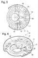
- FIGS. 5 and 6 show a spring plate 5 with partial centering surfaces 17; 19 for the inner contour of the Endwindung, wherein between the Operazentrier vom 17; 19 a gutter 35 is arranged for dirt and moisture.
- the partial centering surfaces 17; 19 ends radially inward in the direction of the gutter 35, the widens in the direction of the sleeve portion 9.
- the partial centering surface 17 in the region of an end stop 37 for the end turn has an outlet region 39 in the direction of the helical spring, which has a smaller outer radius than the inner contour of the helical spring, so that an undercut is created, which offers space for the outlet of the end turn.
Landscapes
- Engineering & Computer Science (AREA)
- Mechanical Engineering (AREA)
- General Engineering & Computer Science (AREA)
- Springs (AREA)
- Polishing Bodies And Polishing Tools (AREA)
- Vehicle Body Suspensions (AREA)
- Fluid-Damping Devices (AREA)
Abstract
Description
- Die Erfindung betrifft einen Federteller gemäß dem Oberbegriff von Patentanspruch 1.
- Die DE 42 03 658 C2 beschreibt insbesondere für ein Fahrzeugfederbein einen Federteller, der für die Endwindung einer Schraubenfeder ein Profil aufweist, das die Schraubenfeder radial zentriert und gegen eine Verdrehung abstützt. Der Federteller verfügt über einen unrunden Umfangsbereich, an dem sich die Schraubenfeder radial abstützt. Wie aus der Figur 4 der DE 42 03 658 C2 ersichtlich ist, liegt die Schraubenfeder nahezu im Bereich der gesamten Endwindung mit ihrem Innendurchmesser am Federteller an.
- Diese räumliche Ausgestaltung eines Federtellers ist in der Theorie sehr günstig, da die Federkraft der Schraubenfeder großflächig abgestützt wird. Des weiteren kann durch das unrunde Profil der Schraubenfederauflage auch eine Verdrehsicherungsfunktion erreicht werden. Das Problem besteht jedoch darin, dass die Endwindung einer Feder unter Berücksichtigung der Fertigungskosten nur in einem eingeschränkten Toleranzbereich gefertigt werden kann, so dass die im Stand der Technik beschriebene Kombination einer Schraubenfeder mit einem Federteller nur schwerlich umsetzbar ist.
- Wenn die Schraubenfeder nicht optimal auf dem Federteller aufliegt, dann treten einerseits hohe Spannungen im Federteller auf. Diese erhöhten Spannungen könnten u. U. durch die Verwendung entsprechend belastbarer Werkstoffe aufgenommen werden. Ein ebenso großes Problem stellen jedoch die Geräusche dar, die bei Längenänderungen der Schraubenfeder aufgrund einer Federungsbewegung auftreten. Vielfach werden die Geräuschprobleme durch die Verwendung einer Unterlage aus einem Kunststoff zwischen der Schraubenfeder und dem Federteller unterbunden. Bei dieser Lösung wird jedoch nicht die Ursache der Geräuschbildung behoben, sondern nur die Auswirkungen. Bei älteren Fahrzeugen kann die Unterlage auch verschlissen sein, so dass dann das Geräusch deutlich vernehmbar ist.
- Aufgabe der vorliegenden Erfindung ist es, einen Federteller im Hinblick auf eine Geräuschbildung mit einer Schraubenfeder zu minimieren.
- Erfindungsgemäß wird die Aufgabe dadurch gelöst, dass die Zentrierfläche in einzelne Teilzentrierflächen gegliedert ist, die an der Umfangskontur der Schraubenfeder zur Anlage kommen.
- Die in Teilzentrierflächen gegliederte Gesamtzentrierfläche führt zu einer deutlichen Geräuschreduzierung, da etwaige Formabweichungen in Freiräumen zwischen den Teilzentrierflächen kompensiert werden können.
- In weiterer vorteilhafter Ausgestaltung der Erfindung greift jeweils an der Innen- und Außenkontur mindestens eine Teilzentrierfläche an, wobei die Teilzentrierflächen für die Außen- und Innenkontur der Schraubenfeder in Umfangsrichtung versetzt zueinander angeordnet sind. Einer Teilzentrierfläche an der Innenkontur liegt an der Außenkontur der Schraubenfeder eine Lücke gegenüber, so dass die Feder keinesfalls zwischen zwei gegenüberliegenden Teilzentrierflächen eingeklemmt sein kann.
- Im Hinblick auf eine möglichst kleine Gesamtzentrierfläche und eine gleichmäßige Verteilung der Teilzentrierflächen ist die an der Außenkontur der Schraubenfeder angreifende Zentrierfläche etwa im Bereich des halben Umfangswinkels zwischen einer ersten und einer letzten an der Innenkontur der Schraubenfeder angreifenden Zentrierfläche angeordnet.
- In diesem Sinne kommt an der Außenkontur der Schraubenfeder nur eine Teilzentrierfläche mit einem beschränkten Umfangswinkel zur Anlage.
- In weiterer vorteilhafter Ausgestaltung weist die Teilzentrierfläche in Richtung der Schraubenfeder auf einem Auslaufbereich einen kleineren Außenradius auf als die Innenkontur der Schraubenfeder. Etwaige Durchmesserabweichungen der Schraubenfeder führen somit nicht zu einem Verklemmen mit einer Teilzentrierfläche.
- Damit sich auf dem Federteller möglichst wenig Feuchtigkeit und Schmutz sammeln kann, ist zwischen zwei an der Innenkontur der Schraubenfeder angreifenden Teilzentrierflächen eine Ablaufrinne ausgeformt.
- Zur Festigkeitssteigerung des Federtellers enden die Teilzentrierflächen nach radial innen in Richtung der Ablaufrinne.
- Die Teilzentrierflächen sind parallel zu einer gleichmäßig runden Berührlinie der Schraubenfeder auf dem Federteller angeordnet, so dass eine einfache runde Endwindung verwendet werden kann, die sich im Vergleich zu einer unrunden Endwindung leichter herstellen lässt.
- Bei einer Ausführungsform ist eine Verbindungskontur zwischen zwei Teilzentrierflächen an der Innenkontur der Schraubenfeder als eine ungekrümmt verlaufende Schrägfläche ausgeführt. Diese Federtellerform ist besonders formstabil.
- Im Hinblick auf einen geringen Umformgrad am Federteller wird ein Verdrehsicherungsanschlag für die Schraubenfeder von einer aufgestellten Zunge des Federtellers gebildet.
- Anhand der folgenden Figurenbeschreibung soll die Erfindung näher erläutert werden.
- Es zeigt:
- Fig. 1
- Gesamtdarstellung eines Federtellers an einem Federbein
- Fig. 2
- Draufsicht des Federtellers aus Fig. 1
- Fig. 3
- Schnittdarstellung des Federtellers aus Fig. 1
- Fig. 4
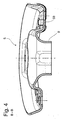
- Weitere Schnittdarstellung des Federtellers aus Fig. 1
- Fig. 5 u. 6
- Federteller mit einer Ablaufrinne
- Die Fig. 1 zeigt sehr stark vereinfacht einen Ausschnitt aus einem Federbein 1, an dessen Zylinder 3 ein Federteller 5 befestigt ist, der einen Schraubenfeder 7 trägt.
- Aus der Zusammenschau der Fig. 2 bis 4 ist der Federteller 5 entsprechend der Fig. 1 als Einzelteil erkennbar, der einen Hülsenabschnitt 9 für die Befestigung am Zylinder aufweist. Dieser Hülsenabschnitt 9 geht in eine schrägverlaufende Abstützfläche 11 über, auf der eine Endwindung 13 der Schraubenfeder 7 zur Anlage kommt. In der Draufsicht nach Fig. 2 ist die Berührlinie 15 der Endwindung 13 auf der Abstützfläche 11 als dünne Volllinie dargestellt. Aus der Ebene der Abstützfläche erstreckt sich radial innen bezogen auf die Berührlinie der Endwindung eine Zentrierfläche, die in einzelne Teilzentrierflächen 17; 19 gegliedert ist und an der Umfangskontur, in dieser Darstellung an der Innenkontur, der Schraubenfeder zur Anlage kommen. Auch eine Außenkontur der Schraubenfeder wird von einer sich auf einem beschränkten Umfangswinkel erstreckende Zentrierfläche 21 abgestützt, wobei die Teilzentrierflächen 17; 19; 21 parallel zu der gleichmäßig runden Berührlinie 15 für die Schraubenfeder angeordnet sind. Die Teilzentrierflächen 17; 19; 21, die an der Innen- und Außenkontur angreifen sind in Umfangsrichtung versetzt zueinander angeordnet, so dass jweils Freiräume 23; 25; 27 zwischen den Teilzentrierflächen 23; 25; 27 vorliegen, die ggf. Form- und Lageabweichungen der Endwindung bezogen auf die Teilzentrierflächen, die sich stanztechnisch wesentlich präziser herstellen lassen, kompensieren. Dabei ist die an der Außenkontur der Schraubenfeder angreifende Zentrierfläche 21 etwa im Bereich des halben Umfangswinkels zwischen einer ersten und einer letzten an der Innenkontur angreifenden Zentrierfläche 17; 19 angeordnet. Folglich sind insgesamt nur drei Teilzentrierflächen 17; 19; 21 wirksam, die die radiale Abstützung der Endwindung der Schraubenfeder übernehmen.
- In diesem Ausführungsbeispiel ist eine Verbindungskontur 29 zwischen den Zentrierflächen 17; 19 an der Innenkontur der Schraubenfeder als eine ungekrümmt verlaufende Schrägfläche ausgeführt. Dieses Gestaltungsmerkmal wirkt sich stark verfestigend auf den gesamten Federteller 5 aus, so dass ein sich der Abstützfläche 11 nach radial außen anschließender Randbereich mit Öffnungen 31 zur Gewichtsminimierung versehen werden kann.
- Als Verdrehsicherung für die Endwindung 13 der Schraubenfeder 7 dient eine aus der axialen Abstützfläche 11 ausgestanzten und aufgestellten Zunge 33 des Federtellers 5.
- Die Figuren 5 und 6 zeigen einen Federteller 5 mit Teilzentrierflächen 17; 19 für die Innenkontur der Endwindung, wobei zwischen den Teilzentrierflächen 17; 19 eine Ablaufrinne 35 für Schmutz und Feuchtigkeit angeordnet ist. Die Teilzentrierflächen 17; 19 enden nach radial innen in Richtung der Ablaufrinne 35, die sich in Richtung des Hülsenabschnitts 9 verbreitert. Die Teilzentrierfläche 17 im Bereich eines Endanschlags 37 für die Endwindung weist einen Auslaufbereich 39 in Richtung der Schraubenfeder auf, der einen kleineren Außenradius besitzt als die Innenkontur der Schraubenfeder, so dass eine Hinterschneidung entsteht, die Bauraum für den Auslauf der Endwindung bietet.
- Insgesamt steht mit dem erfindungsgemäßen Federteller 5 ein leichtes Bauteil zur Verfügung, das, wie Versuche gezeigt haben, auch ohne Federunterlage keine Geräusche durch Reibkontakt zwischen den Teilzentrierflächen 17; 19 ; 21 und der Schraubenfeder 7 aufkommen lässt.
Claims (10)
- Federteller, insbesondere für ein Federbein, umfassend eine axiale Abstützfläche für eine Endwindung einer Schraubenfeder, wobei die Schraubenfeder von radialen Zentrierflächen im Bereich einer Umfangskontur der Endwindung zentriert wird,
dadurch gekennzeichnet,
dass die Zentrierfläche in einzelne Teilzentrierflächen (17; 19; 21) gegliedert ist, die an der Umfangskontur der Schraubenfeder (7) zur Anlage kommen. - Federteller nach Anspruch 1,
dadurch gekennzeichnet,
dass an der Innen- und Außenkontur jeweils mindestens eine Teilzentrierfläche (17; 19; 21) angreift, wobei die Teilzentrierflächen (17; 19; 21) für die Außen- und Innenkontur der Schraubenfeder (7) in Umfangsrichtung versetzt zueinander angeordnet sind. - Federteller nach Anspruch 2,
dadurch gekennzeichnet,
dass die an der Außenkontur der Schraubenfeder (7) angreifende Zentrierfläche (21) etwa im Bereich des halben Umfangswinkels zwischen einer ersten und einer letzten an der Innenkontur der Schraubenfeder angreifenden Zentrierfläche (17; 19) angeordnet ist. - Federteller nach Anspruch 1,
dadurch gekennzeichnet,
dass an der Außenkontur der Schraubenfeder (7) nur eine Zentrierfläche (21) mit einem beschränkten Umfangswinkel zur Anlage kommt. - Federteller nach Anspruch 1,
dadurch gekennzeichnet,
dass die Teilzentrierfläche (17; 19) in Richtung der Innenkontur der Schraubenfeder (7) auf einem Auslaufbereich einen kleinerer Außenradius (39) aufweist als die Innenkontur der Schraubenfeder (7). - Federteller nach Anspruch 1,
dadurch gekennzeichnet,
dass zwischen zwei an der Innenkontur der Schraubenfeder (7) angreifenden Teilzentrierflächen (17; 19) eine Ablaufrinne (35) ausgeformt ist. - Federteller nach Anspruch 6,
dadurch gekennzeichnet,
dass die Teilzentrierflächen (17; 19) nach radial innen in Richtung der Ablaufrinne (35) enden. - Federteller nach Anspruch 1,
dadurch gekennzeichnet,
dass die Teilzentrierflächen (17; 19; 21) parallel zu einer gleichmäßig runden Berührlinie (15) der Schraubenfeder (7) auf dem Federteller (5) angeordnet sind. - Federteller nach Anspruch 1,
dadurch gekennzeichnet,
dass eine Verbindungskontur (29) zwischen zwei Teilzentrierflächen (17; 19) an der Innenkontur der Schraubenfeder als eine ungekrümmt verlaufende Schrägfläche ausgeführt ist. - Federteller nach Anspruch 1,
dadurch gekennzeichnet,
dass ein Verdrehsicherungsanschlag für die Schraubenfeder (7) von einer aufgestellten Zunge (33) des Federtellers (5) gebildet wird.
Priority Applications (1)
| Application Number | Priority Date | Filing Date | Title |
|---|---|---|---|
| SI200530125T SI1637367T1 (sl) | 2004-09-16 | 2005-09-09 | Vzmetni kroznik |
Applications Claiming Priority (1)
| Application Number | Priority Date | Filing Date | Title |
|---|---|---|---|
| DE102004044752A DE102004044752B3 (de) | 2004-09-16 | 2004-09-16 | Federteller |
Publications (3)
| Publication Number | Publication Date |
|---|---|
| EP1637367A2 true EP1637367A2 (de) | 2006-03-22 |
| EP1637367A3 EP1637367A3 (de) | 2006-04-05 |
| EP1637367B1 EP1637367B1 (de) | 2007-11-14 |
Family
ID=35335692
Family Applications (1)
| Application Number | Title | Priority Date | Filing Date |
|---|---|---|---|
| EP05019611A Expired - Lifetime EP1637367B1 (de) | 2004-09-16 | 2005-09-09 | Federteller |
Country Status (7)
| Country | Link |
|---|---|
| US (1) | US8919753B2 (de) |
| EP (1) | EP1637367B1 (de) |
| AT (1) | ATE378205T1 (de) |
| DE (2) | DE102004044752B3 (de) |
| ES (1) | ES2296032T3 (de) |
| PT (1) | PT1637367E (de) |
| SI (1) | SI1637367T1 (de) |
Families Citing this family (4)
| Publication number | Priority date | Publication date | Assignee | Title |
|---|---|---|---|---|
| DE102005028761A1 (de) * | 2005-06-22 | 2007-01-04 | Zf Friedrichshafen Ag | Federteller für einen Schwingungsdämpfer |
| WO2009054636A1 (en) * | 2007-10-24 | 2009-04-30 | Lg Electronics, Inc. | Linear compressor |
| DE102010028290B4 (de) * | 2010-04-28 | 2019-01-31 | Zf Friedrichshafen Ag | Federteller |
| US10816055B2 (en) * | 2018-04-27 | 2020-10-27 | Tenneco Automotive Operating Company Inc. | Damper bumper cap with labyrinth air passageway |
Citations (1)
| Publication number | Priority date | Publication date | Assignee | Title |
|---|---|---|---|---|
| DE4203658C2 (de) | 1992-02-08 | 1995-07-13 | Bayerische Motoren Werke Ag | Schraubenfederabstützung, insbesondere an einem Fahrzeugfederbein |
Family Cites Families (18)
| Publication number | Priority date | Publication date | Assignee | Title |
|---|---|---|---|---|
| CH380546A (it) * | 1960-10-26 | 1964-07-31 | Gomma Antivibranti Applic | Rondella antivibrante in gomma per sospensioni a molla elicoidale |
| DE2938101C2 (de) | 1979-09-20 | 1981-10-08 | Daimler-Benz Ag, 7000 Stuttgart | Federteller mit einer Stützrille für eine Schraubenfeder |
| JPS5769134A (en) * | 1980-10-13 | 1982-04-27 | Kayaba Ind Co Ltd | Spring seat |
| DE3442108A1 (de) * | 1984-11-17 | 1986-05-22 | Fichtel & Sachs Ag, 8720 Schweinfurt | Federbein fuer fahrzeuge |
| JP2632825B2 (ja) * | 1987-01-14 | 1997-07-23 | 株式会社ユニシアジェックス | スプリングシート |
| DE4104859C1 (de) * | 1991-02-16 | 1992-07-09 | Dr.Ing.H.C. F. Porsche Ag, 7000 Stuttgart, De | |
| US5421565A (en) * | 1994-08-11 | 1995-06-06 | General Motors Corporation | Suspension spring insulator |
| JP3149702B2 (ja) * | 1994-10-05 | 2001-03-26 | トヨタ自動車株式会社 | スプリングシート構造 |
| JP3836178B2 (ja) * | 1996-01-17 | 2006-10-18 | 株式会社ショーワ | ストラット型懸架装置 |
| JPH10138727A (ja) * | 1996-11-14 | 1998-05-26 | Nissan Motor Co Ltd | サスペンション構造 |
| US6155544A (en) * | 1998-10-09 | 2000-12-05 | Chrysler Corporation | Vehicle shock absorber and strut damper spring seat pad having a discontinuous spring seat surface |
| FR2789944A1 (fr) * | 1999-02-19 | 2000-08-25 | Michelin & Cie | Jambe de force d'une suspension de roue de type mac pherson |
| DE60014440T2 (de) * | 2000-01-03 | 2005-11-17 | Ibérica de Reproducción Asistida, S.L. | Vorrichtung zur künstlichen befruchtung von schweinen |
| FR2825126B1 (fr) * | 2001-05-22 | 2004-02-20 | Allevard Rejna Technologie Fro | Systeme anti-rotation et anti-migration d'un ressort sur ses appuis |
| JP3801947B2 (ja) | 2001-05-29 | 2006-07-26 | 三菱製鋼株式会社 | スプリングシート |
| JP3992097B2 (ja) * | 2002-01-30 | 2007-10-17 | カヤバ工業株式会社 | ストラット型懸架装置 |
| DE10258936A1 (de) * | 2002-12-17 | 2004-07-01 | Volkswagen Ag | Federbein für eine Kraftfahrzeug-Radaufhängung |
| DE10336151A1 (de) * | 2003-08-07 | 2005-03-10 | Zahnradfabrik Friedrichshafen | Schwingungsdämpfer in Leichtbauweise |
-
2004
- 2004-09-16 DE DE102004044752A patent/DE102004044752B3/de not_active Expired - Fee Related
-
2005
- 2005-09-09 AT AT05019611T patent/ATE378205T1/de not_active IP Right Cessation
- 2005-09-09 EP EP05019611A patent/EP1637367B1/de not_active Expired - Lifetime
- 2005-09-09 ES ES05019611T patent/ES2296032T3/es not_active Expired - Lifetime
- 2005-09-09 SI SI200530125T patent/SI1637367T1/sl unknown
- 2005-09-09 PT PT05019611T patent/PT1637367E/pt unknown
- 2005-09-09 DE DE502005001948T patent/DE502005001948D1/de not_active Expired - Lifetime
- 2005-09-13 US US11/225,278 patent/US8919753B2/en not_active Expired - Fee Related
Patent Citations (1)
| Publication number | Priority date | Publication date | Assignee | Title |
|---|---|---|---|---|
| DE4203658C2 (de) | 1992-02-08 | 1995-07-13 | Bayerische Motoren Werke Ag | Schraubenfederabstützung, insbesondere an einem Fahrzeugfederbein |
Also Published As
| Publication number | Publication date |
|---|---|
| US8919753B2 (en) | 2014-12-30 |
| DE502005001948D1 (de) | 2007-12-27 |
| DE102004044752B3 (de) | 2006-01-12 |
| US20060061025A1 (en) | 2006-03-23 |
| ES2296032T3 (es) | 2008-04-16 |
| EP1637367B1 (de) | 2007-11-14 |
| SI1637367T1 (sl) | 2008-04-30 |
| EP1637367A3 (de) | 2006-04-05 |
| PT1637367E (pt) | 2008-01-04 |
| ATE378205T1 (de) | 2007-11-15 |
Similar Documents
| Publication | Publication Date | Title |
|---|---|---|
| EP1233205B1 (de) | Federungsanordnung | |
| EP0424388B1 (de) | Spanneinrichtung zum axialen festspannen eines werkzeuges, insbesondere einer scheibe | |
| EP2414180A1 (de) | Elastomergelen | |
| EP3423317A1 (de) | Lufttrocknerpatrone und schraubenfeder für lufttrocknerpatrone | |
| EP0493731B1 (de) | Elastisches Lager | |
| EP3867124B1 (de) | Elektromechanisches lenksystem mit einem federelement für ein untersetzungsgetriebe des lenksystems | |
| DE102021206084A1 (de) | Bremssattel mit einer Blende | |
| DE102004037202A1 (de) | Schutzelement für ein Lager | |
| DE69004477T2 (de) | Rolle. | |
| EP1637367B1 (de) | Federteller | |
| DE102020105412A1 (de) | Getriebegehäuseeinheit mit gewölbter Wellfederauflage für axialen Spielausgleich | |
| EP0631081A1 (de) | Anschlussvorrichtung für Rohrleitungen mit geschlitztem Klemmring | |
| DE69811118T2 (de) | Schwingungsdämpfender ring für die radaufhängung eines kraftfahrzeuges | |
| DE19856688B4 (de) | Magnethaltestruktur für einen Linearmotor | |
| EP3771841B1 (de) | Lagerschale für ein kugelgelenk sowie kugelgelenk | |
| EP3106691B1 (de) | Lagerfassung, verteilungselement und vakuumpume | |
| DD233397A5 (de) | Kreuzgelenk | |
| EP2181270A2 (de) | Befestigungsanordnung für ein gelenklager | |
| WO2020011597A1 (de) | Schlepprollenhohlachse, schlepprollenmontageset, fahrtreppenstufe umfassend eine schlepprollenhohlachse sowie verfahren zur montage einer schlepprolle unter verwendung eines schlepprollenmontagesets | |
| EP3186527B1 (de) | Knickfedereinrichtung | |
| DE102020113706B3 (de) | Montagehilfe und Verfahren zur Montage und Demontage von Blockierelementen an einem Federbein | |
| DE102022104980A1 (de) | Lenkungsaktuator | |
| DE20021481U1 (de) | Federwegbegrenzungselement | |
| DE20005583U1 (de) | Verbindungselement für eine elastische Verbindung zweier Bauteile | |
| DE102007015590B3 (de) | Schwingungsdämpfer |
Legal Events
| Date | Code | Title | Description |
|---|---|---|---|
| PUAI | Public reference made under article 153(3) epc to a published international application that has entered the european phase |
Free format text: ORIGINAL CODE: 0009012 |
|
| PUAL | Search report despatched |
Free format text: ORIGINAL CODE: 0009013 |
|
| AK | Designated contracting states |
Kind code of ref document: A2 Designated state(s): AT BE BG CH CY CZ DE DK EE ES FI FR GB GR HU IE IS IT LI LT LU LV MC NL PL PT RO SE SI SK TR |
|
| AX | Request for extension of the european patent |
Extension state: AL BA HR MK YU |
|
| AK | Designated contracting states |
Kind code of ref document: A3 Designated state(s): AT BE BG CH CY CZ DE DK EE ES FI FR GB GR HU IE IS IT LI LT LU LV MC NL PL PT RO SE SI SK TR |
|
| AX | Request for extension of the european patent |
Extension state: AL BA HR MK YU |
|
| RIC1 | Information provided on ipc code assigned before grant |
Ipc: B60G 15/06 20060101AFI20051201BHEP Ipc: F16F 9/32 20060101ALI20060210BHEP |
|
| 17P | Request for examination filed |
Effective date: 20060317 |
|
| AKX | Designation fees paid |
Designated state(s): AT BE BG CH CY CZ DE DK EE ES FI FR GB GR HU IE IS IT LI LT LU LV MC NL PL PT RO SE SI SK TR |
|
| GRAP | Despatch of communication of intention to grant a patent |
Free format text: ORIGINAL CODE: EPIDOSNIGR1 |
|
| GRAS | Grant fee paid |
Free format text: ORIGINAL CODE: EPIDOSNIGR3 |
|
| GRAA | (expected) grant |
Free format text: ORIGINAL CODE: 0009210 |
|
| AK | Designated contracting states |
Kind code of ref document: B1 Designated state(s): AT BE BG CH CY CZ DE DK EE ES FI FR GB GR HU IE IS IT LI LT LU LV MC NL PL PT RO SE SI SK TR |
|
| REG | Reference to a national code |
Ref country code: GB Ref legal event code: FG4D Free format text: NOT ENGLISH |
|
| REG | Reference to a national code |
Ref country code: CH Ref legal event code: EP |
|
| REG | Reference to a national code |
Ref country code: IE Ref legal event code: FG4D Free format text: LANGUAGE OF EP DOCUMENT: GERMAN |
|
| REF | Corresponds to: |
Ref document number: 502005001948 Country of ref document: DE Date of ref document: 20071227 Kind code of ref document: P |
|
| REG | Reference to a national code |
Ref country code: PT Ref legal event code: SC4A Free format text: AVAILABILITY OF NATIONAL TRANSLATION Effective date: 20071221 |
|
| REG | Reference to a national code |
Ref country code: SE Ref legal event code: TRGR |
|
| GBT | Gb: translation of ep patent filed (gb section 77(6)(a)/1977) |
Effective date: 20080130 |
|
| REG | Reference to a national code |
Ref country code: ES Ref legal event code: FG2A Ref document number: 2296032 Country of ref document: ES Kind code of ref document: T3 |
|
| PG25 | Lapsed in a contracting state [announced via postgrant information from national office to epo] |
Ref country code: NL Free format text: LAPSE BECAUSE OF FAILURE TO SUBMIT A TRANSLATION OF THE DESCRIPTION OR TO PAY THE FEE WITHIN THE PRESCRIBED TIME-LIMIT Effective date: 20071114 |
|
| NLV1 | Nl: lapsed or annulled due to failure to fulfill the requirements of art. 29p and 29m of the patents act | ||
| PG25 | Lapsed in a contracting state [announced via postgrant information from national office to epo] |
Ref country code: IS Free format text: LAPSE BECAUSE OF FAILURE TO SUBMIT A TRANSLATION OF THE DESCRIPTION OR TO PAY THE FEE WITHIN THE PRESCRIBED TIME-LIMIT Effective date: 20080314 Ref country code: FI Free format text: LAPSE BECAUSE OF FAILURE TO SUBMIT A TRANSLATION OF THE DESCRIPTION OR TO PAY THE FEE WITHIN THE PRESCRIBED TIME-LIMIT Effective date: 20071114 Ref country code: BG Free format text: LAPSE BECAUSE OF FAILURE TO SUBMIT A TRANSLATION OF THE DESCRIPTION OR TO PAY THE FEE WITHIN THE PRESCRIBED TIME-LIMIT Effective date: 20080214 Ref country code: LT Free format text: LAPSE BECAUSE OF FAILURE TO SUBMIT A TRANSLATION OF THE DESCRIPTION OR TO PAY THE FEE WITHIN THE PRESCRIBED TIME-LIMIT Effective date: 20071114 Ref country code: LV Free format text: LAPSE BECAUSE OF FAILURE TO SUBMIT A TRANSLATION OF THE DESCRIPTION OR TO PAY THE FEE WITHIN THE PRESCRIBED TIME-LIMIT Effective date: 20071114 Ref country code: PL Free format text: LAPSE BECAUSE OF FAILURE TO SUBMIT A TRANSLATION OF THE DESCRIPTION OR TO PAY THE FEE WITHIN THE PRESCRIBED TIME-LIMIT Effective date: 20071114 |
|
| ET | Fr: translation filed | ||
| PG25 | Lapsed in a contracting state [announced via postgrant information from national office to epo] |
Ref country code: DK Free format text: LAPSE BECAUSE OF FAILURE TO SUBMIT A TRANSLATION OF THE DESCRIPTION OR TO PAY THE FEE WITHIN THE PRESCRIBED TIME-LIMIT Effective date: 20071114 |
|
| PG25 | Lapsed in a contracting state [announced via postgrant information from national office to epo] |
Ref country code: RO Free format text: LAPSE BECAUSE OF FAILURE TO SUBMIT A TRANSLATION OF THE DESCRIPTION OR TO PAY THE FEE WITHIN THE PRESCRIBED TIME-LIMIT Effective date: 20071114 |
|
| PLBE | No opposition filed within time limit |
Free format text: ORIGINAL CODE: 0009261 |
|
| STAA | Information on the status of an ep patent application or granted ep patent |
Free format text: STATUS: NO OPPOSITION FILED WITHIN TIME LIMIT |
|
| REG | Reference to a national code |
Ref country code: IE Ref legal event code: FD4D |
|
| 26N | No opposition filed |
Effective date: 20080815 |
|
| PG25 | Lapsed in a contracting state [announced via postgrant information from national office to epo] |
Ref country code: IE Free format text: LAPSE BECAUSE OF FAILURE TO SUBMIT A TRANSLATION OF THE DESCRIPTION OR TO PAY THE FEE WITHIN THE PRESCRIBED TIME-LIMIT Effective date: 20071114 |
|
| PG25 | Lapsed in a contracting state [announced via postgrant information from national office to epo] |
Ref country code: GR Free format text: LAPSE BECAUSE OF FAILURE TO SUBMIT A TRANSLATION OF THE DESCRIPTION OR TO PAY THE FEE WITHIN THE PRESCRIBED TIME-LIMIT Effective date: 20080215 |
|
| PG25 | Lapsed in a contracting state [announced via postgrant information from national office to epo] |
Ref country code: EE Free format text: LAPSE BECAUSE OF FAILURE TO SUBMIT A TRANSLATION OF THE DESCRIPTION OR TO PAY THE FEE WITHIN THE PRESCRIBED TIME-LIMIT Effective date: 20071114 Ref country code: MC Free format text: LAPSE BECAUSE OF NON-PAYMENT OF DUE FEES Effective date: 20080930 |
|
| PG25 | Lapsed in a contracting state [announced via postgrant information from national office to epo] |
Ref country code: CY Free format text: LAPSE BECAUSE OF FAILURE TO SUBMIT A TRANSLATION OF THE DESCRIPTION OR TO PAY THE FEE WITHIN THE PRESCRIBED TIME-LIMIT Effective date: 20071114 |
|
| PG25 | Lapsed in a contracting state [announced via postgrant information from national office to epo] |
Ref country code: AT Free format text: LAPSE BECAUSE OF NON-PAYMENT OF DUE FEES Effective date: 20080909 |
|
| REG | Reference to a national code |
Ref country code: CH Ref legal event code: PL |
|
| PG25 | Lapsed in a contracting state [announced via postgrant information from national office to epo] |
Ref country code: LU Free format text: LAPSE BECAUSE OF NON-PAYMENT OF DUE FEES Effective date: 20080909 Ref country code: HU Free format text: LAPSE BECAUSE OF FAILURE TO SUBMIT A TRANSLATION OF THE DESCRIPTION OR TO PAY THE FEE WITHIN THE PRESCRIBED TIME-LIMIT Effective date: 20080515 |
|
| PG25 | Lapsed in a contracting state [announced via postgrant information from national office to epo] |
Ref country code: CH Free format text: LAPSE BECAUSE OF NON-PAYMENT OF DUE FEES Effective date: 20090930 Ref country code: LI Free format text: LAPSE BECAUSE OF NON-PAYMENT OF DUE FEES Effective date: 20090930 |
|
| PGFP | Annual fee paid to national office [announced via postgrant information from national office to epo] |
Ref country code: CZ Payment date: 20100813 Year of fee payment: 6 Ref country code: SI Payment date: 20100730 Year of fee payment: 6 Ref country code: SK Payment date: 20100816 Year of fee payment: 6 |
|
| PGFP | Annual fee paid to national office [announced via postgrant information from national office to epo] |
Ref country code: PT Payment date: 20100903 Year of fee payment: 6 |
|
| PG25 | Lapsed in a contracting state [announced via postgrant information from national office to epo] |
Ref country code: IT Free format text: LAPSE BECAUSE OF NON-PAYMENT OF DUE FEES Effective date: 20080930 |
|
| REG | Reference to a national code |
Ref country code: PT Ref legal event code: MM4A Free format text: LAPSE DUE TO NON-PAYMENT OF FEES Effective date: 20120309 |
|
| PG25 | Lapsed in a contracting state [announced via postgrant information from national office to epo] |
Ref country code: CZ Free format text: LAPSE BECAUSE OF NON-PAYMENT OF DUE FEES Effective date: 20110909 |
|
| PG25 | Lapsed in a contracting state [announced via postgrant information from national office to epo] |
Ref country code: PT Free format text: LAPSE BECAUSE OF NON-PAYMENT OF DUE FEES Effective date: 20120309 |
|
| REG | Reference to a national code |
Ref country code: SI Ref legal event code: KO00 Effective date: 20120413 |
|
| REG | Reference to a national code |
Ref country code: SK Ref legal event code: MM4A Ref document number: E 2871 Country of ref document: SK Effective date: 20110909 |
|
| PG25 | Lapsed in a contracting state [announced via postgrant information from national office to epo] |
Ref country code: SK Free format text: LAPSE BECAUSE OF NON-PAYMENT OF DUE FEES Effective date: 20110909 |
|
| PG25 | Lapsed in a contracting state [announced via postgrant information from national office to epo] |
Ref country code: SI Free format text: LAPSE BECAUSE OF NON-PAYMENT OF DUE FEES Effective date: 20110910 |
|
| PGFP | Annual fee paid to national office [announced via postgrant information from national office to epo] |
Ref country code: GB Payment date: 20140903 Year of fee payment: 10 Ref country code: SE Payment date: 20140911 Year of fee payment: 10 |
|
| PGFP | Annual fee paid to national office [announced via postgrant information from national office to epo] |
Ref country code: FR Payment date: 20140906 Year of fee payment: 10 |
|
| PGFP | Annual fee paid to national office [announced via postgrant information from national office to epo] |
Ref country code: BE Payment date: 20140912 Year of fee payment: 10 |
|
| REG | Reference to a national code |
Ref country code: SE Ref legal event code: EUG |
|
| GBPC | Gb: european patent ceased through non-payment of renewal fee |
Effective date: 20150909 |
|
| PG25 | Lapsed in a contracting state [announced via postgrant information from national office to epo] |
Ref country code: SE Free format text: LAPSE BECAUSE OF NON-PAYMENT OF DUE FEES Effective date: 20150910 |
|
| REG | Reference to a national code |
Ref country code: FR Ref legal event code: ST Effective date: 20160531 |
|
| PG25 | Lapsed in a contracting state [announced via postgrant information from national office to epo] |
Ref country code: GB Free format text: LAPSE BECAUSE OF NON-PAYMENT OF DUE FEES Effective date: 20150909 |
|
| PG25 | Lapsed in a contracting state [announced via postgrant information from national office to epo] |
Ref country code: FR Free format text: LAPSE BECAUSE OF NON-PAYMENT OF DUE FEES Effective date: 20150930 |
|
| PG25 | Lapsed in a contracting state [announced via postgrant information from national office to epo] |
Ref country code: BE Free format text: LAPSE BECAUSE OF NON-PAYMENT OF DUE FEES Effective date: 20150930 |
|
| PGFP | Annual fee paid to national office [announced via postgrant information from national office to epo] |
Ref country code: TR Payment date: 20190905 Year of fee payment: 15 |
|
| PGFP | Annual fee paid to national office [announced via postgrant information from national office to epo] |
Ref country code: ES Payment date: 20191001 Year of fee payment: 15 |
|
| REG | Reference to a national code |
Ref country code: ES Ref legal event code: FD2A Effective date: 20220117 |
|
| PG25 | Lapsed in a contracting state [announced via postgrant information from national office to epo] |
Ref country code: ES Free format text: LAPSE BECAUSE OF NON-PAYMENT OF DUE FEES Effective date: 20200910 |
|
| PG25 | Lapsed in a contracting state [announced via postgrant information from national office to epo] |
Ref country code: TR Free format text: LAPSE BECAUSE OF NON-PAYMENT OF DUE FEES Effective date: 20200909 |
|
| PGFP | Annual fee paid to national office [announced via postgrant information from national office to epo] |
Ref country code: DE Payment date: 20220609 Year of fee payment: 18 |
|
| P01 | Opt-out of the competence of the unified patent court (upc) registered |
Effective date: 20230528 |
|
| REG | Reference to a national code |
Ref country code: DE Ref legal event code: R119 Ref document number: 502005001948 Country of ref document: DE |
|
| PG25 | Lapsed in a contracting state [announced via postgrant information from national office to epo] |
Ref country code: DE Free format text: LAPSE BECAUSE OF NON-PAYMENT OF DUE FEES Effective date: 20240403 |