EP1637708A2 - Dispositif de commande d'un système de clapet d'air d'un véhicule automobile - Google Patents
Dispositif de commande d'un système de clapet d'air d'un véhicule automobile Download PDFInfo
- Publication number
- EP1637708A2 EP1637708A2 EP05019289A EP05019289A EP1637708A2 EP 1637708 A2 EP1637708 A2 EP 1637708A2 EP 05019289 A EP05019289 A EP 05019289A EP 05019289 A EP05019289 A EP 05019289A EP 1637708 A2 EP1637708 A2 EP 1637708A2
- Authority
- EP
- European Patent Office
- Prior art keywords
- actuator
- switch
- measuring device
- electrical signal
- air flap
- Prior art date
- Legal status (The legal status is an assumption and is not a legal conclusion. Google has not performed a legal analysis and makes no representation as to the accuracy of the status listed.)
- Granted
Links
Images


Classifications
-
- G—PHYSICS
- G05—CONTROLLING; REGULATING
- G05D—SYSTEMS FOR CONTROLLING OR REGULATING NON-ELECTRIC VARIABLES
- G05D23/00—Control of temperature
- G05D23/19—Control of temperature characterised by the use of electric means
- G05D23/1919—Control of temperature characterised by the use of electric means characterised by the type of controller
- G05D23/1921—Control of temperature characterised by the use of electric means characterised by the type of controller using a thermal motor
-
- F—MECHANICAL ENGINEERING; LIGHTING; HEATING; WEAPONS; BLASTING
- F01—MACHINES OR ENGINES IN GENERAL; ENGINE PLANTS IN GENERAL; STEAM ENGINES
- F01P—COOLING OF MACHINES OR ENGINES IN GENERAL; COOLING OF INTERNAL-COMBUSTION ENGINES
- F01P7/00—Controlling of coolant flow
- F01P7/02—Controlling of coolant flow the coolant being cooling-air
- F01P7/10—Controlling of coolant flow the coolant being cooling-air by throttling amount of air flowing through liquid-to-air heat exchangers
- F01P7/12—Controlling of coolant flow the coolant being cooling-air by throttling amount of air flowing through liquid-to-air heat exchangers by thermostatic control
-
- B—PERFORMING OPERATIONS; TRANSPORTING
- B60—VEHICLES IN GENERAL
- B60K—ARRANGEMENT OR MOUNTING OF PROPULSION UNITS OR OF TRANSMISSIONS IN VEHICLES; ARRANGEMENT OR MOUNTING OF PLURAL DIVERSE PRIME-MOVERS IN VEHICLES; AUXILIARY DRIVES FOR VEHICLES; INSTRUMENTATION OR DASHBOARDS FOR VEHICLES; ARRANGEMENTS IN CONNECTION WITH COOLING, AIR INTAKE, GAS EXHAUST OR FUEL SUPPLY OF PROPULSION UNITS IN VEHICLES
- B60K11/00—Arrangement in connection with cooling of propulsion units
- B60K11/08—Air inlets for cooling; Shutters or blinds therefor
- B60K11/085—Air inlets for cooling; Shutters or blinds therefor with adjustable shutters or blinds
-
- F—MECHANICAL ENGINEERING; LIGHTING; HEATING; WEAPONS; BLASTING
- F01—MACHINES OR ENGINES IN GENERAL; ENGINE PLANTS IN GENERAL; STEAM ENGINES
- F01P—COOLING OF MACHINES OR ENGINES IN GENERAL; COOLING OF INTERNAL-COMBUSTION ENGINES
- F01P2025/00—Measuring
-
- F—MECHANICAL ENGINEERING; LIGHTING; HEATING; WEAPONS; BLASTING
- F01—MACHINES OR ENGINES IN GENERAL; ENGINE PLANTS IN GENERAL; STEAM ENGINES
- F01P—COOLING OF MACHINES OR ENGINES IN GENERAL; COOLING OF INTERNAL-COMBUSTION ENGINES
- F01P2070/00—Details
- F01P2070/04—Details using electrical heating elements
-
- Y—GENERAL TAGGING OF NEW TECHNOLOGICAL DEVELOPMENTS; GENERAL TAGGING OF CROSS-SECTIONAL TECHNOLOGIES SPANNING OVER SEVERAL SECTIONS OF THE IPC; TECHNICAL SUBJECTS COVERED BY FORMER USPC CROSS-REFERENCE ART COLLECTIONS [XRACs] AND DIGESTS
- Y02—TECHNOLOGIES OR APPLICATIONS FOR MITIGATION OR ADAPTATION AGAINST CLIMATE CHANGE
- Y02T—CLIMATE CHANGE MITIGATION TECHNOLOGIES RELATED TO TRANSPORTATION
- Y02T10/00—Road transport of goods or passengers
- Y02T10/80—Technologies aiming to reduce greenhouse gasses emissions common to all road transportation technologies
- Y02T10/88—Optimized components or subsystems, e.g. lighting, actively controlled glasses
Definitions
- the invention relates to a device for controlling an air flap system of a motor vehicle according to the preamble of claim 1.
- Modern cooling systems in particular for drives of motor vehicles, are increasingly subject to complex control requirements for optimizing the cooling capacity as a function of the operating state of the drive. It is desired that arranged in the range of a cooler adjustable air dampers such as slats or blinds can be adjusted defined. In particular, feedback on the position of the louvers on a control unit of the cooling system are desired.
- DE 102 23 686 A1 describes an actuator with a heated expansion element for actuating a radiator shutter or a thermostatic valve, wherein a heating circuit is interrupted in an end position of the actuator by a switch actuated by the actuator.
- the air flap system is part of a main radiator of a cooling system for an internal combustion engine of the motor vehicle, whereby an improved control of the cooling of the internal combustion engine is made possible.
- the electrical signal can be generated by means of a voltage divider from a supply voltage, whereby low production costs and high reliability are possible.
- the adjusting element is designed as an expansion element, preferably with a heating device, wherein the heating device is operable by means of the supply voltage.
- the measuring device comprises a first switch and a second switch, wherein the first switch can be actuated by reaching the first position of the actuator and the second switch by reaching the second position of the actuator.
- the positions of the actuator can be measured easily and reliably.
- at least a third switch for reading a third position of the actuator may be provided, wherein the third switch is actuated by reaching the third position of the actuator.
- the measuring device comprises a stepless measuring element, wherein in a range of movement the actuator is the position of the actuator in a dependent of their electrical signal convertible.
- a very precise control of the louvers is possible, and in particular a temporal behavior of the air damper adjustment can be determined particularly accurately.
- this advantageously comprises an adjustable electrical resistance.
- a reliable stepless measuring element can be provided by mechanical coupling of actuator and adjustable resistance.
- the measuring device and the actuator may preferably be formed as a structural unit, wherein the structural unit is connected to a control unit associated therewith by means of exactly one electrical signal line for signaling the actuator position.
- the structural unit is connected to a control unit associated therewith by means of exactly one electrical signal line for signaling the actuator position.
- the structural unit is connected to a control unit associated therewith by means of exactly one electrical signal line for signaling the actuator position.
- a different voltage of the signal line is assigned to the different readable positions of the actuator.
- the electrical signal can be read out by means of a processor-controlled control circuit.
- a processor-controlled control circuit In this way, a particularly variable control of the device or the louvers is possible, in addition, important parameters such as a temporal behavior of the actuator position can be gerümmelt in a simple manner.
- a fault diagnosis of the system in terms of cable breakage or other malfunctions can be provided in a simple manner.
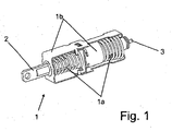
- the device comprises an actuating element 1, which comprises a stationary mounted base body 1 b and a linearly movable actuator 2 on the other hand.
- the actuator 2 is connected to an air flap system, not shown, so that the linear movement of the actuator 2 causes an opening or closing movement of at least one air damper.
- the actuator 1 is designed as an expansion element (see Fig. 1), wherein the actuator 2 comprises a cylinder which is pushed out upon heating of an encapsulated Dehnstoffvolumens from the base body 1 b. This can be done both by an external heating of the actuating element 1 and by an energization of an actuator disposed in the electric heating element.
- the control element For contacting the heating element, the control element has a ground terminal, which corresponds to the housing and a pole 3 for connecting a supply voltage.
- the movement of the actuator 2, in particular the return movement upon cooling of the expansion material is supported by provided springs 1a.
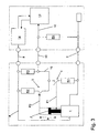
- the stroke H of the actuator 2 is shown in the schematic Fig. 2 to Fig. 4 respectively as a dotted line.
- a first switch 4 and a second switch 5 is provided.
- the switches are presently designed as mechanical switches, but also electronic switches are conceivable, which can be controlled by means of magnetic fields or light.
- the two switches 4, 5 are electrically contacted via a resistor network 6.
- the network is arranged between a ground line 7 (negative pole of a vehicle battery 9) and a line 8 supplying the supply voltage for the expansion element.
- a first node 6a of the network is connected to the ground line 7 and a second node 6b is connected to the supply voltage 8.
- a first resistor R1 and, subsequently, the first switch 4 are connected to the first node 6a.
- a third node 6c of the network follows, in which a branch into two branches takes place.
- the second switch 5 is initially arranged in series, and subsequently a second resistor R2 is arranged in series.
- a third resistor R3 is arranged in the other branch.
- the resistors R2 and R3 are connected on their side remote from the third node 6c in the second node 6b to the supply voltage 8.
- From the third node 6c also branches off a signal line 10, which is occupied according to the following description with the electrical information about the position of the actuator 2.
- the network 6 with the switches 4, 5 and its connections to the supply line 8 and ground line 7 forms a total of a measuring device, by means of which positions of the actuator 2 can be measured and converted into electrical signals.
- the adjusting element 1 and the measuring device 4, 5, 6 according to the above description are preferably formed as a common structural unit 11. This is indicated in the drawings Fig. 2 to Fig. 4 as the assembly 11 surrounding box of a dotted line.
- This unit 11 is only three electrical lines, namely the supply line 8, the ground line 7 (which must not necessarily be designed as a separate cable according to the function of the vehicle mass) and the control line 10, connected to a control unit or control circuit 12.
- the control circuit 12 comprises a processor unit 13 with a programmable microprocessor and a power output stage 14. Processor unit 13 and output stage 14 are connected to one another via a control bus 15, by means of which control and control of the output stage 14 by the processor unit 13 takes place.
- the signal line 10 is connected to the processor unit 13.
- a fourth resistor R4 is connected between signal line 10 and ground line 7.
- resistor R4 is disposed in the region of the control unit 12. In general, however, it can also be arranged in the area of the assembly 11. Regarding its function, it is part of the network 6.
- the resistors R1 to R4 are all ohmic resistors; in general, however, they can also be of complex impedance.
- R3 and R4 are about the same size.
- R1 and R2 are each significantly smaller than R3 and R4, respectively.
- the first switch 4 is actuated by the actuator and in the present case closed, whereas the arranged at the other end of Stellgliedweges second switch 5 is not actuated and open is.
- R1 is significantly smaller than R4
- the supply voltage hereinafter referred to as UV
- the battery voltage 7 is generally zero volts (0V)) at the location of the signal line in a good approximation ratio R1 to R3 divided.
- the first switch 4 is open and only the second switch 5 is actuated and closed by the actuator 2. Since R2 is significantly smaller than R3, R2 and R4 form, to a good approximation, a voltage divider and the signal voltage is 0.5 UV ⁇ US ⁇ UV.
- each of the actuator states “fully retracted” (first readable position P1), “partially extended”, and “fully extended” (second readable position P2) is associated with precisely one different voltage value US of the signal line.
- the voltage value US is in each case relative to the supply voltage UV, but this is known to the processor unit 13 via the control bus 15.
- the supply voltage UV will also not be variable in size.
- a metered heating of the expansion element 1 is rather carried out by a controlled pulsation of the supply voltage UV.
- the signal input is always at ground potential 0V, in particular regardless of how long the expansion element is energized with heating current.
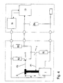
- the second embodiment according to FIG. 5 differs from the first embodiment as follows:
- a third switch 20 and a fifth resistor R5 are provided.
- the third switch 20 is connected at one end to the third node 6c.
- the fifth resistor connects the other end of the third switch 20 to the second node 6b.
- the resistors R2, R3 and R5 are thus arranged in parallel between the nodes 6b and 6c.
- the third switch 20 is actuated in a partially extended position of the actuator 2, which is present in the present example shortly before reaching the end position of the actuator 2.
- This position is a third readable position P3 of the actuator, in this position P3, the first switch 4 is opened, the second switch 5 is opened and the third switch 20 is closed.
- the fifth resistor R5 has a value different from that of the second resistor R2 but smaller than that of the third resistor R3.
- the third voltage associated signal voltage is thus greater than 0.5 UV, but smaller than the second switch 5 associated signal voltage. Overall, therefore, depending on the position of the actuator 2, four different signal voltages US before.
- the expansion element is energized with a DC voltage until the third readable position P3 is reached.
- the power amplifier begins to energize the actuator 2 with a pulsed voltage of adjustable duty cycle (PWM signal).
- PWM signal adjustable duty cycle
- the duty cycle is adjusted by the processor unit 13 so that the actuator 2 remains in the third position P3.
- a faulty control can be avoided by having readable positions P1, P2 with different voltages on both sides of the third position P3.
- the power will be increased at voltage 0.5V. Otherwise, should the actuator already be located above the third position, which would require a reduction in performance, this fault condition would soon be detected by reaching the end position (second readable position P2).
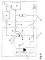
- the third embodiment according to FIG. 6 differs from the first embodiment in that the network 6 is replaced by an adjustable ohmic resistor RV.
- This has a first base terminal 30 which is connected to the ground line 7 and a second base terminal 31 which is connected to the supply line 8. Between the ground terminals 30, 31 there is a constant maximum value of the resistor RV.
- An adjustable tap 32 which may be formed as a sliding contact over a carbon track, is connected to the signal line 10.
- the resistor R4 between signal line 10 and ground line 7 in the region of the control circuit 12 is present. This can improve the fault diagnosis of the system as described above.
- the adjustable resistor RV already forms a voltage divider 6 for itself.
- the tap 32 is mechanically connected to the actuator 2 so that movement of the actuator 2 causes movement of the tap 32 above the carbon web.
- each position or position PV of the actuator 2 is assigned to a different division ratio of the voltage divider 6 and thus a different signal voltage US steplessly.
- the variable resistor RV thus forms a stepless measuring element.
- the signal voltage depends monotonically on the stroke of the actuator 2 and in particular is proportional to the stroke of the actuator. 2
- adjustable resistors may be present.
- other measuring elements such as an incremental encoder can also be used.
- a movement of the actuator 2 would be reported as a number of pulses to the processor unit 13, so that as a result stepless measurement of the actuator position is also possible.
- Such an arrangement could be realized partially or completely without a resistor network.
- the third embodiment are suitable for determining the temporal behavior of the control element 1 in response to energization by the output stage 14 or to environmental parameters (ambient temperature).
- environmental parameters ambient temperature
- Such measured parameters may in turn be incorporated into a software algorithm of the processor unit in order to allow the most optimal possible control of the air flap system and thus the cooling system of the vehicle.
Landscapes
- Engineering & Computer Science (AREA)
- Chemical & Material Sciences (AREA)
- Combustion & Propulsion (AREA)
- Mechanical Engineering (AREA)
- General Engineering & Computer Science (AREA)
- Physics & Mathematics (AREA)
- General Physics & Mathematics (AREA)
- Automation & Control Theory (AREA)
- Air-Conditioning For Vehicles (AREA)
- Cooling, Air Intake And Gas Exhaust, And Fuel Tank Arrangements In Propulsion Units (AREA)
Applications Claiming Priority (1)
| Application Number | Priority Date | Filing Date | Title |
|---|---|---|---|
| DE102004045019A DE102004045019A1 (de) | 2004-09-15 | 2004-09-15 | Vorrichtung zur Steuerung eines Luftklappensystems eines Kraftfahrzeugs |
Publications (3)
| Publication Number | Publication Date |
|---|---|
| EP1637708A2 true EP1637708A2 (fr) | 2006-03-22 |
| EP1637708A3 EP1637708A3 (fr) | 2010-03-31 |
| EP1637708B1 EP1637708B1 (fr) | 2018-06-27 |
Family
ID=35056841
Family Applications (1)
| Application Number | Title | Priority Date | Filing Date |
|---|---|---|---|
| EP05019289.7A Ceased EP1637708B1 (fr) | 2004-09-15 | 2005-09-06 | Dispositif de commande d'un système de clapet d'air d'un véhicule automobile |
Country Status (2)
| Country | Link |
|---|---|
| EP (1) | EP1637708B1 (fr) |
| DE (1) | DE102004045019A1 (fr) |
Families Citing this family (1)
| Publication number | Priority date | Publication date | Assignee | Title |
|---|---|---|---|---|
| DE102018201469B4 (de) | 2018-01-31 | 2022-05-19 | Röchling Automotive SE & Co. KG | OBD-fähige Kfz-Luftklappenvorrichtung mit verstellwegbasierter Funktionsdiagnose |
Family Cites Families (4)
| Publication number | Priority date | Publication date | Assignee | Title |
|---|---|---|---|---|
| GB586031A (en) * | 1943-02-06 | 1947-03-05 | Garrett Corp Airsearch Mfg Com | A temperature control means applicable to oil coolers for aircraft |
| JPS5150934Y2 (fr) * | 1972-04-28 | 1976-12-07 | ||
| US6077052A (en) * | 1998-09-02 | 2000-06-20 | Ingersoll-Rand Company | Fluid compressor aftercooler temperature control system and method |
| DE10223686B4 (de) * | 2002-05-23 | 2014-10-09 | Behr Thermot-Tronik Gmbh | Verfahren zum Ansteuern eines beheizbaren Dehnstoffelements |
-
2004
- 2004-09-15 DE DE102004045019A patent/DE102004045019A1/de not_active Withdrawn
-
2005
- 2005-09-06 EP EP05019289.7A patent/EP1637708B1/fr not_active Ceased
Also Published As
| Publication number | Publication date |
|---|---|
| EP1637708B1 (fr) | 2018-06-27 |
| EP1637708A3 (fr) | 2010-03-31 |
| DE102004045019A1 (de) | 2006-03-30 |
Similar Documents
| Publication | Publication Date | Title |
|---|---|---|
| WO2010084099A1 (fr) | Configuration de circuit pour la commande d'une soupape d'injection | |
| DE10335904A1 (de) | Verfahren und Vorrichtung zur bidirektionalen Eindraht-Datenübertragung | |
| DE102016221477A1 (de) | Vorrichtung zum Betreiben und zur Ermittlung eines Betriebszustands eines elektromagnetischen Aktors sowie Kupplungsvorrichtung und Kraftfahrzeugantriebsstrang | |
| WO2013107714A1 (fr) | Chauffage électrique | |
| DE3733623A1 (de) | Einrichtung zur einstellung einer betriebskenngroesse einer brennkraftmaschine | |
| WO2012084002A1 (fr) | Circuit de commande pour un relais électromagnétique | |
| DE102014219130B4 (de) | Diagnoseschaltung und Verfahren zum Betreiben einer Diagnoseschaltung | |
| DE102010063744A1 (de) | Schaltungsanordnung und Verfahren zur Anlaufstrombegrenzung bei einem Starter | |
| EP1637708B1 (fr) | Dispositif de commande d'un système de clapet d'air d'un véhicule automobile | |
| DE10007691A1 (de) | Verfahren und Vorrichtung zum Speichern und/oder Auslesen von Daten eines Kraftstoffzumesssystems | |
| WO2013178367A2 (fr) | Procédé et dispositif pour surveiller un dispositif actionneur | |
| DE4322472B4 (de) | Schaltungsanordnung zur Überwachung eines Stellungsgebers | |
| WO2005106227A1 (fr) | Procede de diagnostic d'un circuit de commande | |
| EP0309753A1 (fr) | Procédé de surveillance de charge inductive | |
| DE4443350C1 (de) | Schaltungsanordnung zur Ansteuerung und Überwachung elektrischer Lasten in einem Kraftfahrzeug | |
| DE112007001754T5 (de) | Spiegeleinstellmechanismus, Seitenspiegeleinheit und Verfahren dafür | |
| DE10250921B4 (de) | Schaltungsanordnung und Verfahren zur sequentiellen Klassifizierung einer Mehrzahl von ansteuerbaren Bauteilen | |
| DE102021210690B3 (de) | Verfahren zum Erkennen der Position eines Aktorelements | |
| DE2733006C3 (de) | Temperaturwächter | |
| WO2001042637A2 (fr) | Procede et dispositif destines a entrainer un element de reglage dans un vehicule motorise | |
| DE69702226T2 (de) | Heizelementsteuerschaltung mit veränderlichem Widerstand assoziiert mit einem Sensor zur Erfassung von Sauerstoff in Abgasen | |
| DE102020210254A1 (de) | Elektronische last zum verbauen in der leistungsversorgung einer fahrzeuglampe | |
| DE102009041451B4 (de) | Ansteuereinheit für elektrische und/oder pneumatische Verstellantriebe | |
| DE102012224181A1 (de) | Elektrische Schaltung mit einem Relais und Verfahren zur Beurteilung einer Funktionsfähigkeit eines Relais | |
| WO2001051302A1 (fr) | Circuit electrique pour la commande d'un moteur electrique dans un vehicule |
Legal Events
| Date | Code | Title | Description |
|---|---|---|---|
| PUAI | Public reference made under article 153(3) epc to a published international application that has entered the european phase |
Free format text: ORIGINAL CODE: 0009012 |
|
| AK | Designated contracting states |
Kind code of ref document: A2 Designated state(s): AT BE BG CH CY CZ DE DK EE ES FI FR GB GR HU IE IS IT LI LT LU LV MC NL PL PT RO SE SI SK TR |
|
| AX | Request for extension of the european patent |
Extension state: AL BA HR MK YU |
|
| PUAL | Search report despatched |
Free format text: ORIGINAL CODE: 0009013 |
|
| AK | Designated contracting states |
Kind code of ref document: A3 Designated state(s): AT BE BG CH CY CZ DE DK EE ES FI FR GB GR HU IE IS IT LI LT LU LV MC NL PL PT RO SE SI SK TR |
|
| AX | Request for extension of the european patent |
Extension state: AL BA HR MK YU |
|
| RIC1 | Information provided on ipc code assigned before grant |
Ipc: G05D 23/19 20060101ALI20100219BHEP Ipc: F01P 7/12 20060101AFI20051017BHEP Ipc: B60K 11/08 20060101ALI20100219BHEP |
|
| 17P | Request for examination filed |
Effective date: 20100930 |
|
| 17Q | First examination report despatched |
Effective date: 20101108 |
|
| AKX | Designation fees paid |
Designated state(s): CZ DE ES FR GB IT |
|
| RAP1 | Party data changed (applicant data changed or rights of an application transferred) |
Owner name: MAHLE BEHR GMBH & CO. KG |
|
| GRAP | Despatch of communication of intention to grant a patent |
Free format text: ORIGINAL CODE: EPIDOSNIGR1 |
|
| INTG | Intention to grant announced |
Effective date: 20180209 |
|
| GRAS | Grant fee paid |
Free format text: ORIGINAL CODE: EPIDOSNIGR3 |
|
| GRAJ | Information related to disapproval of communication of intention to grant by the applicant or resumption of examination proceedings by the epo deleted |
Free format text: ORIGINAL CODE: EPIDOSDIGR1 |
|
| GRAL | Information related to payment of fee for publishing/printing deleted |
Free format text: ORIGINAL CODE: EPIDOSDIGR3 |
|
| GRAR | Information related to intention to grant a patent recorded |
Free format text: ORIGINAL CODE: EPIDOSNIGR71 |
|
| GRAA | (expected) grant |
Free format text: ORIGINAL CODE: 0009210 |
|
| INTC | Intention to grant announced (deleted) | ||
| RIN1 | Information on inventor provided before grant (corrected) |
Inventor name: BIELESCH, THOMAS |
|
| AK | Designated contracting states |
Kind code of ref document: B1 Designated state(s): CZ DE ES FR GB IT |
|
| INTG | Intention to grant announced |
Effective date: 20180523 |
|
| REG | Reference to a national code |
Ref country code: GB Ref legal event code: FG4D Free format text: NOT ENGLISH |
|
| REG | Reference to a national code |
Ref country code: DE Ref legal event code: R096 Ref document number: 502005015852 Country of ref document: DE |
|
| REG | Reference to a national code |
Ref country code: FR Ref legal event code: PLFP Year of fee payment: 14 |
|
| PGFP | Annual fee paid to national office [announced via postgrant information from national office to epo] |
Ref country code: FR Payment date: 20180924 Year of fee payment: 14 |
|
| PG25 | Lapsed in a contracting state [announced via postgrant information from national office to epo] |
Ref country code: CZ Free format text: LAPSE BECAUSE OF FAILURE TO SUBMIT A TRANSLATION OF THE DESCRIPTION OR TO PAY THE FEE WITHIN THE PRESCRIBED TIME-LIMIT Effective date: 20180627 |
|
| PGFP | Annual fee paid to national office [announced via postgrant information from national office to epo] |
Ref country code: DE Payment date: 20181001 Year of fee payment: 14 |
|
| PG25 | Lapsed in a contracting state [announced via postgrant information from national office to epo] |
Ref country code: IT Free format text: LAPSE BECAUSE OF FAILURE TO SUBMIT A TRANSLATION OF THE DESCRIPTION OR TO PAY THE FEE WITHIN THE PRESCRIBED TIME-LIMIT Effective date: 20180627 Ref country code: ES Free format text: LAPSE BECAUSE OF FAILURE TO SUBMIT A TRANSLATION OF THE DESCRIPTION OR TO PAY THE FEE WITHIN THE PRESCRIBED TIME-LIMIT Effective date: 20180627 |
|
| REG | Reference to a national code |
Ref country code: DE Ref legal event code: R097 Ref document number: 502005015852 Country of ref document: DE |
|
| PLBE | No opposition filed within time limit |
Free format text: ORIGINAL CODE: 0009261 |
|
| STAA | Information on the status of an ep patent application or granted ep patent |
Free format text: STATUS: NO OPPOSITION FILED WITHIN TIME LIMIT |
|
| GBPC | Gb: european patent ceased through non-payment of renewal fee |
Effective date: 20180927 |
|
| 26N | No opposition filed |
Effective date: 20190328 |
|
| PG25 | Lapsed in a contracting state [announced via postgrant information from national office to epo] |
Ref country code: GB Free format text: LAPSE BECAUSE OF NON-PAYMENT OF DUE FEES Effective date: 20180927 |
|
| REG | Reference to a national code |
Ref country code: DE Ref legal event code: R119 Ref document number: 502005015852 Country of ref document: DE |
|
| PG25 | Lapsed in a contracting state [announced via postgrant information from national office to epo] |
Ref country code: DE Free format text: LAPSE BECAUSE OF NON-PAYMENT OF DUE FEES Effective date: 20200401 |
|
| PG25 | Lapsed in a contracting state [announced via postgrant information from national office to epo] |
Ref country code: FR Free format text: LAPSE BECAUSE OF NON-PAYMENT OF DUE FEES Effective date: 20190930 |