EP1637752A2 - Articulation à pivot - Google Patents
Articulation à pivot Download PDFInfo
- Publication number
- EP1637752A2 EP1637752A2 EP05019946A EP05019946A EP1637752A2 EP 1637752 A2 EP1637752 A2 EP 1637752A2 EP 05019946 A EP05019946 A EP 05019946A EP 05019946 A EP05019946 A EP 05019946A EP 1637752 A2 EP1637752 A2 EP 1637752A2
- Authority
- EP
- European Patent Office
- Prior art keywords
- bellows seal
- pivot joint
- bellows
- folds
- housing
- Prior art date
- Legal status (The legal status is an assumption and is not a legal conclusion. Google has not performed a legal analysis and makes no representation as to the accuracy of the status listed.)
- Withdrawn
Links
Images

Classifications
-
- F—MECHANICAL ENGINEERING; LIGHTING; HEATING; WEAPONS; BLASTING
- F16—ENGINEERING ELEMENTS AND UNITS; GENERAL MEASURES FOR PRODUCING AND MAINTAINING EFFECTIVE FUNCTIONING OF MACHINES OR INSTALLATIONS; THERMAL INSULATION IN GENERAL
- F16C—SHAFTS; FLEXIBLE SHAFTS; ELEMENTS OR CRANKSHAFT MECHANISMS; ROTARY BODIES OTHER THAN GEARING ELEMENTS; BEARINGS
- F16C11/00—Pivots; Pivotal connections
- F16C11/04—Pivotal connections
- F16C11/06—Ball-joints; Other joints having more than one degree of angular freedom, i.e. universal joints
- F16C11/0666—Sealing means between the socket and the inner member shaft
- F16C11/0671—Sealing means between the socket and the inner member shaft allowing operative relative movement of joint parts due to flexing of the sealing means
-
- F—MECHANICAL ENGINEERING; LIGHTING; HEATING; WEAPONS; BLASTING
- F16—ENGINEERING ELEMENTS AND UNITS; GENERAL MEASURES FOR PRODUCING AND MAINTAINING EFFECTIVE FUNCTIONING OF MACHINES OR INSTALLATIONS; THERMAL INSULATION IN GENERAL
- F16C—SHAFTS; FLEXIBLE SHAFTS; ELEMENTS OR CRANKSHAFT MECHANISMS; ROTARY BODIES OTHER THAN GEARING ELEMENTS; BEARINGS
- F16C11/00—Pivots; Pivotal connections
- F16C11/04—Pivotal connections
- F16C11/06—Ball-joints; Other joints having more than one degree of angular freedom, i.e. universal joints
- F16C11/0619—Ball-joints; Other joints having more than one degree of angular freedom, i.e. universal joints the female part comprising a blind socket receiving the male part
- F16C11/0623—Construction or details of the socket member
- F16C11/0628—Construction or details of the socket member with linings
Definitions
- the invention relates to a pivot joint according to the preamble of claim 1.
- the object of the invention is in contrast to provide a pivot joint available, in which a greater torsion of the bellows seal without material damage is possible.
- the pivot joint according to the invention is characterized by a bellows seal with folds whose pleat ridges and valleys are arranged radially and reduce the torsional stress material stresses in the bellows seal against a design without wrinkles. Due to the arrangement of pockets which are distributed uniformly on the circumference of the sealing bellows, the wrinkles are formed. The wrinkles have fold backs and valleys which run radially onto the bellows seal longitudinal axis.
- the term "radially arranged” encompasses all pleat ridges and valleys in which the middle planes in the bellows seal longitudinal axis, which divide symmetrically in the longitudinal direction of the pleat ridges and valleys, are located to cut.
- the pockets are arranged in an advantageous manner on a circular sealing surface perpendicular to the bellows sealing longitudinal axis or a portion of the sealing bellows in the form of a truncated cone or a spherical segment.
- the sealing bellows in the region of the pockets can take any shape, such as a bent and / or curved contour.
- the dorsal and valley lines do not intersect the bellows sealing longitudinal axis.
- the folds referred to below as radial folds, allow torsion of the bellows seal about its longitudinal axis without loading the material under operating conditions beyond the permissible limits.
- the wall thickness of the bellows seal in the region of the folds, is lower than in the other areas.
- a reduction in the wall thickness in the region of the folds advantageously reduces the torsional rigidity of the bellows seal, i. the forces required to twist or twist the bellows seal are reduced.
- a pin portion has a circumferential groove on which the bellows seal bears under prestress.
- a pivot pin comprising a pin and a ball is mounted in a housing.
- the bellows seal seals at the journal portion and the housing.
- the bellows seal for example, made of elastomeric material is designed so that it is snapped under bias in the groove provided on the journal portion. The groove secures the bellows seal against axial slippage on the pin section.
- a clamping ring surrounds the bellows seal at least partially and presses it against the journal section.
- the clamping ring is inserted into a groove provided in the bellows seal and increases by an additional contact force the sealing effect.
- About the bias of the clamping ring is adjustable, whether a relative movement between the pin portion and the bellows seal occurs under normal operating conditions or not.
- the bellows seal abuts axially against the counterpart component. Due to the elasticity of the elastomer material, the bellows seal presses against an end face of the counterpart component. This creates between the bellows seal and the counterpart component another sealing point, which prevents in addition to the seal between the bellows seal and the pin portion an entry of contamination in the pivot joint.
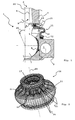
- FIGS. 1 to 3 Identical components in FIGS. 1 to 3 are designated by the same reference numerals.
- a pivot joint 1 according to FIG. 1 is provided for the movable connection of two components.
- An unillustrated component is connected to a housing 2 of the pivot joint 1.
- the housing 2 has for attachment to the component, not shown, a mounting eye 3, alike, for example, a threaded rod may be provided.
- a counterpart component 4 is connected to a journal section 5 of a pivot pin 6 protruding from the housing 2.
- a portion of the pin portion 5 is conical and arranged without play in a conical bore formed in the counterpart part 4.
- the component not shown, for example, a steering knuckle of a suspension, which is connected via the pivot joint 1 with a running example, as a wishbone counter-member 4.
- the arranged in the housing 2 pivot pin 6 can perform rotational and tilting 9.10.
- the pivot pin 6 comprises a ball 7, which is mounted in a housing 2 arranged in the joint shell 8.
- An elastic bellows seal 11 of preferably elastomeric material is disposed between the housing 2 and the movable pivot pin 6.
- the bellows seal 11 prevents ingress of dirt and moisture into the joint shell 8.
- the housing 2 and partially enclosed by the bellows seal 11 space are filled with lubricant, the bellows seal 11 prevents leakage of the lubricant.
- a first side of the bellows seal 11 is firmly connected.
- a clamping ring 12 is inserted in the bellows seal 11, which connects the bellows seal 11 to the housing 2 immovable.
- the bellows seal 11 can be connected to the housing 2, for example by vulcanization, gluing or by a positive connection, such as a rolling-in process.
- a round wire ring 14 is inserted in the bellows seal 11.
- the round wire ring 14 presses the bellows seal 11 against the journal portion 5, so that the bellows seal 11 at least partially encloses the journal cut 5 in the region of the groove 13 with prestressing.
- the contact pressure is chosen so that no relative movement between the bellows seal 11 and the pin portion 5 occurs under normal operating conditions twist angles of eg ⁇ 30 °.
- the bellows seal 11 adheres to the journal portion 5 and seals in the groove area, the joint components such as ball 7 and joint shell 8 reliably against dirt and moisture from.
- the annular surface 15 is the lateral surface of a truncated cone, which is inclined, for example, at an angle a of about 80 ° relative to the bellows sealing longitudinal axis 20.
- the angle ⁇ has a value of 90 °, in other embodiments, the angle may have a value less than 80 °.
- the radial folds may extend wholly or partially over the width of the lateral surface.
- the folds 16 can also be formed from pockets 17 of different depths. Changeable pocket depths can occur both in a pocket 17 and between adjacent pockets 17.
- a rotation of the bellows seal 11 is realized by a deformation in the region of the radial folds 16.
- the folds 16 are formed as pockets 17, which are arranged regularly on the entire circumference of the annular surface 15.
- the transitions from one pocket 17 to the next as well as transitions in the pocket bottom are designed to reduce material tensions, for example with radii R1 and R2, see FIG. 3.
- the wall thickness s is preferably lower than in other areas of the bellows seal 11.
- the bellows seal 11 can be twisted even more easily.
- the folds 16 stiffen the annular surface 15 against buckling, so that the bellows seal 11 is deformed during tilting movements 10 essentially in the bead area 18, see FIG. 1. This ensures in an advantageous manner that the annular surface 15 of the bellows seal 11 itself with a reduced Wall thickness does not bulge and wears due to contact with the counter component 4.
- the bellows seal 11 is arranged in the pivot joint 1 so that in principle a relative movement, ie, a sliding movement between the pivot pin 6 and the bellows seal 11 is possible.
- the round wire ring 14 must have a defined preload which, on the one hand, enables the relative movement and, on the other hand, applies a sufficiently high compressive force for sealing the bellows seal 11 with respect to the pivot pin 6.
- the bellows seal 11 Since a relative movement of the bellows seal 11 due to changing friction conditions between the elastomer material of the bellows seal 11 and a steel material of the pivot pin 6, for example, by evaporation of plasticizers is not guaranteed over the entire life, the bellows seal 11 is torsionally soft for security, ie executed with radial folds 16. An adhesion of the bellows seal 11 on the pivot pin 6 thus does not lead to a functional impairment of the pivot joint 1 by failure of the bellows seal 11 due to material overstress.
- To increase the sealing effect between the pin portion 5 and the bellows seal 11 is provided as a further sealing point an axial bearing 19 of the bellows seal 11 on the counterpart component 4, see Fig. 1. This embodiment is preferably recommended when relative movement between the pin portion 5 and the counterpart component 4 and the bellows seal 11 occur.
Landscapes
- Engineering & Computer Science (AREA)
- General Engineering & Computer Science (AREA)
- Mechanical Engineering (AREA)
- Sealing Devices (AREA)
- Pivots And Pivotal Connections (AREA)
- Diaphragms And Bellows (AREA)
Applications Claiming Priority (1)
| Application Number | Priority Date | Filing Date | Title |
|---|---|---|---|
| DE102004044776A DE102004044776B4 (de) | 2004-09-16 | 2004-09-16 | Zapfengelenk |
Publications (2)
| Publication Number | Publication Date |
|---|---|
| EP1637752A2 true EP1637752A2 (fr) | 2006-03-22 |
| EP1637752A3 EP1637752A3 (fr) | 2006-06-21 |
Family
ID=35448399
Family Applications (1)
| Application Number | Title | Priority Date | Filing Date |
|---|---|---|---|
| EP05019946A Withdrawn EP1637752A3 (fr) | 2004-09-16 | 2005-09-14 | Articulation à pivot |
Country Status (2)
| Country | Link |
|---|---|
| EP (1) | EP1637752A3 (fr) |
| DE (1) | DE102004044776B4 (fr) |
Cited By (1)
| Publication number | Priority date | Publication date | Assignee | Title |
|---|---|---|---|---|
| JP2014211182A (ja) * | 2013-04-18 | 2014-11-13 | Nok株式会社 | ボールジョイント用ダストカバー |
Families Citing this family (4)
| Publication number | Priority date | Publication date | Assignee | Title |
|---|---|---|---|---|
| DE102007011360B4 (de) | 2007-03-07 | 2026-03-19 | Zf Friedrichshafen Ag | Kugelzapfen |
| DE102017200757A1 (de) | 2017-01-18 | 2018-07-19 | Zf Friedrichshafen Ag | Dichtungsbalg für ein Gelenk und ein Gelenk mit einem solchen Dichtungsbalg |
| DE102017216488A1 (de) * | 2017-09-18 | 2019-03-21 | Zf Friedrichshafen Ag | Radialkugelgelenk für ein Lenkerbauteil eines Kraftfahrzeugs |
| DE102017217277B3 (de) * | 2017-09-28 | 2018-05-03 | Zf Friedrichshafen Ag | Gelenkanordnung |
Citations (1)
| Publication number | Priority date | Publication date | Assignee | Title |
|---|---|---|---|---|
| EP1000260B1 (fr) | 1997-12-23 | 2001-11-14 | DaimlerChrysler AG | Joint a soufflet pour articulations a pivot, en particulier montees sur des vehicules automobiles |
Family Cites Families (5)
| Publication number | Priority date | Publication date | Assignee | Title |
|---|---|---|---|---|
| GB1050169A (fr) * | 1900-01-01 | |||
| US2304732A (en) * | 1941-05-01 | 1942-12-08 | Columbus Auto Parts | Sealing means for joint structures linking movable members |
| GB911335A (en) * | 1960-09-26 | 1962-11-28 | Automotive Prod Co Ltd | Improvements in or relating to sealing boots for joint assemblies |
| DE6602948U (de) * | 1967-04-05 | 1969-07-17 | Ehrenreich & Cie A | Abdichtungs fuer kugelgelenke, vorzugsweise radgelenke. |
| US6582146B2 (en) * | 2001-02-13 | 2003-06-24 | Trw Inc. | Ball joint seal |
-
2004
- 2004-09-16 DE DE102004044776A patent/DE102004044776B4/de not_active Expired - Fee Related
-
2005
- 2005-09-14 EP EP05019946A patent/EP1637752A3/fr not_active Withdrawn
Patent Citations (1)
| Publication number | Priority date | Publication date | Assignee | Title |
|---|---|---|---|---|
| EP1000260B1 (fr) | 1997-12-23 | 2001-11-14 | DaimlerChrysler AG | Joint a soufflet pour articulations a pivot, en particulier montees sur des vehicules automobiles |
Cited By (1)
| Publication number | Priority date | Publication date | Assignee | Title |
|---|---|---|---|---|
| JP2014211182A (ja) * | 2013-04-18 | 2014-11-13 | Nok株式会社 | ボールジョイント用ダストカバー |
Also Published As
| Publication number | Publication date |
|---|---|
| EP1637752A3 (fr) | 2006-06-21 |
| DE102004044776A1 (de) | 2006-04-27 |
| DE102004044776B4 (de) | 2010-07-15 |
Similar Documents
| Publication | Publication Date | Title |
|---|---|---|
| EP0570625B1 (fr) | Palier pivotant | |
| DE4138582C1 (fr) | ||
| DE3525213A1 (de) | Elastische buchse | |
| EP2964509A1 (fr) | Système de palier à mobilité angulaire pour pignons d'engrenages réducteurs de systèmes de direction électromécaniques | |
| EP1463891A1 (fr) | Joint a rotule | |
| EP0819556B1 (fr) | Pallier à articulation,en particulier pour un guide d'essieu de véhicule automobile | |
| EP0991534B1 (fr) | Joint a rotule monte dans un palier en caoutchouc, presentant une geometrie de palier optimisee en ce qui concerne les tensions | |
| EP1792092B1 (fr) | Joint spherique a soufflet d'etancheite | |
| EP1339557A1 (fr) | Articulation a douille | |
| EP0611892B1 (fr) | Palier d'un tourillon muni d'un collet | |
| DE2403111A1 (de) | Gelenkverbindung | |
| EP0348642A1 (fr) | Joint à rotule | |
| WO2000037821A1 (fr) | Palier en caoutchouc presentant une caracteristique qui varie dans le sens circonferentiel | |
| WO2008119344A2 (fr) | Articulation à rotule | |
| EP4119368B1 (fr) | Palier de pivotement pour le support d'un bras de suspension de véhicule | |
| DE102004044776B4 (de) | Zapfengelenk | |
| EP1391333B2 (fr) | Palier métal-caoutchouc pour monter une barre stabilisatrice d'un véhicule | |
| DE10006178C5 (de) | Elastomerlager | |
| EP0656271A1 (fr) | Pivot, en particulier pour un guide d'essieu d'un véhicule à moteur | |
| WO2018219586A1 (fr) | Coussinet de palier | |
| DE102017213935A1 (de) | Entkopplungseinheit und Wankstabilisator mit einer solchen Entkopplungseinheit | |
| DE102012017892A1 (de) | Drehstützlager | |
| DE102006052917B4 (de) | Hydrolager mit Wegbegrenzung | |
| DE102006046179B4 (de) | Einstellvorrichtung für eine Radaufhängung von Kraftfahrzeugen | |
| EP0748949B1 (fr) | Support radial |
Legal Events
| Date | Code | Title | Description |
|---|---|---|---|
| PUAI | Public reference made under article 153(3) epc to a published international application that has entered the european phase |
Free format text: ORIGINAL CODE: 0009012 |
|
| AK | Designated contracting states |
Kind code of ref document: A2 Designated state(s): AT BE BG CH CY CZ DE DK EE ES FI FR GB GR HU IE IS IT LI LT LU LV MC NL PL PT RO SE SI SK TR |
|
| AX | Request for extension of the european patent |
Extension state: AL BA HR MK YU |
|
| PUAL | Search report despatched |
Free format text: ORIGINAL CODE: 0009013 |
|
| AK | Designated contracting states |
Kind code of ref document: A3 Designated state(s): AT BE BG CH CY CZ DE DK EE ES FI FR GB GR HU IE IS IT LI LT LU LV MC NL PL PT RO SE SI SK TR |
|
| AX | Request for extension of the european patent |
Extension state: AL BA HR MK YU |
|
| RIC1 | Information provided on ipc code assigned before grant |
Ipc: F16J 3/04 20060101ALI20060516BHEP Ipc: F16C 11/06 20060101AFI20051220BHEP |
|
| STAA | Information on the status of an ep patent application or granted ep patent |
Free format text: STATUS: THE APPLICATION HAS BEEN WITHDRAWN |
|
| 18W | Application withdrawn |
Effective date: 20061103 |