EP1638111A2 - Dispositif et méthode pour la mesure d'un assemblage combustible dans une centrale nucléaire - Google Patents
Dispositif et méthode pour la mesure d'un assemblage combustible dans une centrale nucléaire Download PDFInfo
- Publication number
- EP1638111A2 EP1638111A2 EP05017099A EP05017099A EP1638111A2 EP 1638111 A2 EP1638111 A2 EP 1638111A2 EP 05017099 A EP05017099 A EP 05017099A EP 05017099 A EP05017099 A EP 05017099A EP 1638111 A2 EP1638111 A2 EP 1638111A2
- Authority
- EP
- European Patent Office
- Prior art keywords
- instrument carrier
- distance
- measuring
- signal
- fuel assembly
- Prior art date
- Legal status (The legal status is an assumption and is not a legal conclusion. Google has not performed a legal analysis and makes no representation as to the accuracy of the status listed.)
- Granted
Links
Images


Classifications
-
- G—PHYSICS
- G21—NUCLEAR PHYSICS; NUCLEAR ENGINEERING
- G21C—NUCLEAR REACTORS
- G21C17/00—Monitoring; Testing ; Maintaining
- G21C17/06—Devices or arrangements for monitoring or testing fuel or fuel elements outside the reactor core, e.g. for burn-up, for contamination
-
- Y—GENERAL TAGGING OF NEW TECHNOLOGICAL DEVELOPMENTS; GENERAL TAGGING OF CROSS-SECTIONAL TECHNOLOGIES SPANNING OVER SEVERAL SECTIONS OF THE IPC; TECHNICAL SUBJECTS COVERED BY FORMER USPC CROSS-REFERENCE ART COLLECTIONS [XRACs] AND DIGESTS
- Y02—TECHNOLOGIES OR APPLICATIONS FOR MITIGATION OR ADAPTATION AGAINST CLIMATE CHANGE
- Y02E—REDUCTION OF GREENHOUSE GAS [GHG] EMISSIONS, RELATED TO ENERGY GENERATION, TRANSMISSION OR DISTRIBUTION
- Y02E30/00—Energy generation of nuclear origin
- Y02E30/30—Nuclear fission reactors
Definitions
- the invention relates to a measuring device and a method for measuring a fuel assembly in a nuclear power plant.
- fuel elements undergo strong radioactive irradiation. Among other things, this causes changes in the outer geometry of the fuel assemblies. Possible geometric deformations of the fuel elements include bends in the longitudinal axis and twists about the longitudinal axis. Excessively deformed fuel assemblies must be identified to avoid reactor failure. Therefore, they must be examined at regular intervals for their geometric dimensions. For this purpose, various methods are known.
- One possibility is to tension a cable between the fuel element head and foot on a longitudinal side of the fuel assembly and to determine the height of the cable deflection orthogonal to the surface of the fuel element side with the aid of an underwater television camera having a ruler attachment. In this case, the resulting chord length is determined. Although the deflection, but not the twist of a fuel assembly can be detected with these methods.
- movable carriage systems with instrument carriers are generally permanently installed in nuclear power plants, usually in three dimensions, on which various measuring or manipulation devices can be mounted.
- Such carriage systems have position sensors which detect the position of the instrument carrier e.g. capture relative to the fuel pool and thus to a fixedly mounted fuel element.
- a measuring device or a method for measuring a fuel assembly in a nuclear power plant which uses just these position sensor for measuring the fuel assembly.
- a button is mounted on the instrument carrier, which is moved against a measuring point on the fuel assembly.
- the button generates a switching signal as soon as the instrument carrier has approached the fuel element up to a defined distance.
- the traversing movement of the instrument carrier is then stopped and the position information of the position sensors arranged on the instrument carrier or its traversing system is read out.
- the approach of the instrument carrier is in each case in a direction perpendicular to the longitudinal direction of the fuel assembly repeated at this in different longitudinal positions of the fuel assembly.
- a corresponding inspection device has a certain mechanical caster, namely between the triggering of the switching signal from the button to the standstill of the instrument carrier or the entire inspection device. This caster leads to further inaccuracies in the measurement of the fuel assembly.
- the object of the present invention is to specify an improved measuring device and a corresponding measuring method for measuring a fuel element.
- the object is achieved by a measuring device for measuring a fuel assembly in a nuclear power plant, with a fuel assembly in a holder fixing inspection device, wherein the inspection device a movable relative to the holder instrument carrier and a connected to a computing position transducer for determining a position of the instrument carrier contains relative to the holder.
- a signal generator for delivering a measurement signal to the computing device upon reaching a predetermined distance between the instrument carrier and a measuring point on the fuel assembly is mounted.
- the signal generator contains a non-contact, a distance signal generating distance sensor.
- a corresponding inspection device is usually permanently installed in each nuclear power plant, and there usually in the fuel pool.
- the inspection device serves just any way of inspecting a fuel assembly.
- the inspection device therefore has a holder in which the fuel assembly can be fixed. Often this is rotatable in the holder about its longitudinal axis, but lockable in any rotational position, stored.
- such inspection devices usually mounted on a carriage system which can be moved in three dimensions, have an instrument carrier which is suitable for receiving a wide variety of observation, testing or measuring devices such as cameras, lamps, manipulators, grippers, etc.
- the instrument carrier can thus be moved in all three spatial directions with respect to the fixed fuel element.
- this is, or the instrument carrier on the inspection device traversing carriage system equipped with position sensors.
- the permanently installed in the fuel storage tank inspection device thus defines a stationary stationary coordinate system in which also the fuel element rests, where at each time the x, y and z coordinate of the instrument carrier (or a reference point on this) in the coordinate system is known.
- the respective coordinates are e.g. received by corresponding position sensors on the x, y and z axes of the carriage system.
- the inspection device is a device which is usually permanently installed in the nuclear power plant, the corresponding position sensors usually work very well exactly.
- the corresponding measuring devices for example distance sensors, are mounted on the instrument carrier and moved on a known path, eg on an exact straight line which runs approximately parallel to the fuel element (z-axis). , which is why the distance sensor thus likewise traveled on a straight line measures a variable distance to the latter depending on the deformation of the fuel assembly.
- the position sensor on the inspection device thus serves only to control or ensure a correspondingly precise travel path of the distance sensor, wherein the fuel element deformation reflecting measured data are supplied by the distance sensor.
- the measured values are not discharged from a distance sensor, but directly from the position sensor of the inspection device. This is possible if, to determine the position of a specific measuring point on the fuel assembly, the inspection device is moved until it assumes a defined or known position, ie a known distance from the measuring point. Since, on the one hand, the position of the instrument carrier in the coordinate system is known via the position sensor and, on the other hand, the distance (offset) of the measuring point is known, the position of the measuring point on the fuel element can also be calculated or known.
- a distance signal generating distance sensor as a signal generator, which makes it possible to achieve a predeterminable, ie known position or a Detect such distance from the instrument carrier to the measuring point and derive a measurement signal.
- this measurement signal is used as a switching signal in order, at the moment of its occurrence, to derive the current position of the inspection device, which is detected by the position sensor, from the inspection device and to store it as a measured value.
- About the known distance between the instrument carrier and the measuring point can then be calculated in the computing device, the exact location of the measuring point.
- the signal generator may include a threshold value switch which generates the measurement signal at a predetermined distance signal. Otherwise, the measurement signal is passed as a distance signal to the computing device and there guided to a threshold value.
- Non-contact sensors that emit a binary signal as a measurement signal.
- various embodiments conceivable such as non-contact switch with encoders such as Induktivwegaufêtn, ultrasonic transducers or capacitive transducers. Additional position sensors do not need to be installed as the position sensors already installed in the inspection equipment installed in the nuclear power plant are used.
- the measuring device according to the invention is therefore less expensive and cheaper.
- the distance sensor If the distance sensor generates or transmits a distance signal to the computing device, it can be continuously monitored either in the signal generator itself, as described above, or in the computing device.
- the signal generator then gives no binary signal, but e.g. a digital or analog distance signal to the computing device. Only there is the binary measurement signal ("zero" or "one") generated from this.
- the inspection device are already braked to achieve the distance exactly.
- the actual distance between the measuring point and the instrument carrier can be determined after standstill of the instrument carrier, which may deviate slightly from the predeterminable distance.
- the distance signal is followed by a fine correction for the measuring point calculation.
- the distance signal of the distance sensor must be calibrated here only in a much smaller area, namely only in a small environment of the predeterminable distance, as in a measurement between instrument panel and fuel assembly.
- the object is achieved by a method for measuring a fuel assembly in a nuclear power plant, in which the fuel assembly is fixed in a holder of an inspection device, an instrument carrier of the inspection device is moved relative to the fuel element, upon reaching a pre-definable contact-free monitored distance between the instrument carrier and a measurement point on the fuel assembly, a measurement signal is transmitted to a computing device, the local position of the instrument carrier is determined at the occurrence of the measurement signal and transmitted to the computing device, and in the computing device, the spatial position of the measurement point is calculated.
- the traversing movement of the instrument carrier is stopped when the measuring signal occurs, and the distance between the instrument carrier and measuring point and the position of the instrument carrier is determined and transmitted to the computing device when the instrument carrier is at a standstill. Dynamic measurement errors during movements of the instrument carrier are thus excluded, the entire system is at rest and both the position of the instrument carrier and the actual distance between the instrument carrier and the measuring point are determined when the instrument carrier is stationary and transmitted to the computing device, where the final calculation of the spatial position of the measuring point takes place , In this method variant, it is therefore not assumed that the predetermined (nominal) distance between the instrument carrier and the measuring point, but their actual distance determined at the moment of determining the position of the instrument carrier. The method becomes more accurate.
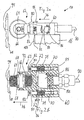
- Fig. 1 shows a measuring device 2 for measuring a fuel assembly 4 in a nuclear power plant.
- the measuring device 2 is firmly installed on the wall 6 in the interior 8 of a fuel storage pool. It comprises a two-part holder 10 for the fuel assembly 4, a fixed to the wall 6 guide rail 12 and a movable on the guide rail 12 device table 14. On the device table 14 a relative to this in two orthogonal directions in space movable instrument carrier 16 is mounted and on this turn a signal generator 18th
- the bracket 10 includes an upper collet 20a and a lower collet 20b.
- head 22 and foot 24 of the fuel assembly are firmly clamped so that it is fixed relative to the wall 6 stationary.
- fuel assembly components such as control rod guide tubes 26 and spacer 28 of the fuel assembly 4 are thus freely accessible.
- the fuel assembly 4 shown in Fig. 1 is a fuel assembly of a pressurized water reactor representative of all types and embodiments of fuel assemblies, e.g. also that of a boiling water reactor. In that case, e.g. the outer fuel element box freely accessible.
- the collet 20b is placed with respect to the entire measuring device 2 so that when clamped fuel element 4 in the center of the top of the foot 24 a Cartesian coordinate system 30 has its origin.
- the X-axis 32 and Y-axis 34 in this case run plane-parallel to the surface 38 of the device table 14, the Z-axis 36 parallel to the guide rail 12.
- the instrument carrier 16 is in turn mounted on the Y-bills 46 and therefore with respect to the device table 14 in the X and Y directions.
- Guide rail 12, X-rail 42 and Y-rail 46 are each provided with displacement sensors 48, 50, and 52, which receive the respective spatial position of the element displaceable thereon and are connected to a computing device 54 outside the fuel element storage pool. Therefore, the exact spatial position of the instrument carrier 16 in the coordinate system 30 is known at any time in the computing device 54.
- the entire arrangement described so far is permanently and permanently installed in the respective nuclear power plant, since the instrument carrier 16 for any inspection or manipulation of fuel elements with a variety of facilities, such as television cameras, grippers, manipulators, tools, measuring equipment etc. can be equipped. In order to always be able to approach local positions with high accuracy for all these tasks, all components are stably executed and their dimensions are precisely known.
- the fixed displacement transducers 48, 50 and 52 are working accurately and are calibrated so that the coordinate system 30 provides an accurate coordinate system in which the location of the instrument carrier 16 is accurately known.
- FIGS. 2a and 2b show a signal generator in mechanical design according to the prior art in detail.
- the signal generator 18 includes a movably mounted on its housing 60 Tastfinger 62 with a pinch roller 64.
- the pinch roller 64 is rotatably mounted on a fixedly mounted in the sensing finger 62 axis 66 with ball bearings 68.
- the entire sensing finger 62 is slidably mounted on slide-in bearings 72 in the axial direction of bolt 70 fixed in housing 60.
- the sensing finger 62 is in this case on the bolt 70 with springs 74 in the direction of the arrow 76, ie from the housing 60 away, biased.
- the pinch roller 64 is not in contact with an outer surface 78 of the fuel assembly 4, representative of e.g. its spacer 28 or control rod guide tube 26.
- the abutment surface 80 of the sensing finger 62 is therefore at the head 82 of the bolt 70, so this is completely rebounded.
- a situation is shown in which the signal generator 18 is approached in the direction of the arrow 76 against the fuel assembly 4, and the outer wall 78, which is why the Tastfinger 62 is spring-loaded relative to the housing 60, so that the stop surface 80 lifts off from the head 82.
- a switch 84 or its switching tongue 88 movably mounted on the switch housing 86, is actuated by the contact surface 92, whereupon the switch 84 transmits an electrical switching signal "1" to the computing device 54 via a signal line 90.
- the switching tongue 88 is relieved, which is why over the line 90, no signal or the switching signal "0" is transmitted to the computing device 54.
- this is shown symbolically by the contact surface 92, the switching tongue 88 releases.
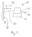
- Fig. 4 shows how on the instrument panel 16 as a signal generator 18 not that of Fig. 2a, b is mounted, but a non-contact distance sensor 120, which is aligned to the fuel assembly 4, so also in the direction of the arrow 76, aligned.
- the distance sensor measures the distance to the outer surface 78 with an ultrasonic wave 122.
- the signal generator 18 is first positioned in front of a selected measuring point 94 on the fuel element 4 in such a way that the measuring point 94 in the direction of the arrow 76, ie in Fig. 2a and 2b in the axial direction of the bolt 70 in front of the pressure roller 64 comes to rest.
- the approach of the measuring point 94 takes place here by observing a camera, not shown, by moving the instrument carrier 16 on the guide rail 12 or the X-rail 42 and the Y-rail 42. The position now reached is shown in FIGS. 2 a and 4 see.
- the instrument carrier 16 and with it the signal generator 18 in the direction of the arrow 76 by sole V civil along the X-rail 42 with the X-drive 40 to the measuring point 94 moves.
- the pinch roller 64 and with it the sensing finger 62 no longer moves in the direction of the arrow 76 to the measuring point 94.
- the housing 60 which is mounted on the instrument carrier 16, does not stop moving. Therefore, the sensing finger 62 slides on the plain bearings 72 along the bolt 70. From the contact surface 92 so the switching tongue 88 of the switch 84 is actuated.
- the switch 86 changes its switching state from "0" to "1" or the distance meter 120 outputs a specific distance signal which corresponds to the predeterminable distance. Via the supply line 90, the switching or distance signal is transmitted to the computing device 54. At this moment, the movement of the instrument carrier 16 is stopped. The position of the instrument carrier 16 is then read out of the displacement sensors 48, 50 and 52 and also transmitted to the computing device 54.
- the exact position of the measuring point 94 in the coordinate system 30 is calculated in the computing device 54.
- the measurement signal 100 is generated in the distance sensor 120 or the computing device 54 in such a way that it changes from “0” and “1" at a distance of 55 mm between the distance sensor 120 and the outer surface 78.
- FIG. 3 shows the switching signal 100 of the switch 86 when the signal generator 18 approaches the measuring point 94.
- the X-distance 96 between the front side 103 of the instrument carrier and the measuring point 94 is plotted on the axis 102. This is more than 57 mm, as long as the pinch roller 64 is not applied to the fuel assembly 4. With commencement of compression of the springs 74, the distance 96 decreases continuously. The switch 84 still remains at its one switching position "0", which is why it still outputs a switching signal 100 of "0" on the output line 90.
- the mechanism of the switch 84 is such that it switches at a distance 96 of exactly 5 mm its switching signal 100 from “0" to "1". This corresponds to a distance 104 of 55 mm on the axis 102.
- the current values of the position sensors 48, 50 and 52 are read out. Only at a distance 96 of about 3 mm, the movement is stopped and reversed in the other direction, the signal generator 18 again moved away from the fuel assembly 4 and moved to the next measurement point.
- the non-contact distance sensor 120 supplies, as a function of its distance from the fuel assembly 4, a signal whose course is shown as a distance signal 106 in FIG.
- the distance signal 106 can be continuously transmitted to the computing device 54 via the signal line 90.
- the switching signal 100 is then generated there.
- the measuring device 2 may have a slight mechanical lag, which is why the actual stop of the signal generator 18 then supplies this with an actual value 110 of the distance signal 106.
- an actual distance 114 of 54.5 mm to the measuring point 94 is determined via the known characteristic of the distance sensor, which only needs to be calibrated around the threshold value 108 over a very narrow range 112. This corrected measured value is included in the calculation of the spatial position of the measuring point 94.
Landscapes
- Physics & Mathematics (AREA)
- Engineering & Computer Science (AREA)
- Plasma & Fusion (AREA)
- General Engineering & Computer Science (AREA)
- High Energy & Nuclear Physics (AREA)
- Monitoring And Testing Of Nuclear Reactors (AREA)
- Length Measuring Devices With Unspecified Measuring Means (AREA)
Applications Claiming Priority (1)
| Application Number | Priority Date | Filing Date | Title |
|---|---|---|---|
| DE102004046052A DE102004046052A1 (de) | 2004-09-21 | 2004-09-21 | Messeinrichtung zur Vermessung eines Brennelementes in einem Kernkraftwerk |
Publications (3)
| Publication Number | Publication Date |
|---|---|
| EP1638111A2 true EP1638111A2 (fr) | 2006-03-22 |
| EP1638111A3 EP1638111A3 (fr) | 2006-06-07 |
| EP1638111B1 EP1638111B1 (fr) | 2007-06-20 |
Family
ID=35432359
Family Applications (1)
| Application Number | Title | Priority Date | Filing Date |
|---|---|---|---|
| EP05017099A Expired - Lifetime EP1638111B1 (fr) | 2004-09-21 | 2005-08-05 | Dispositif et méthode pour la mesure d'un assemblage combustible dans une centrale nucléaire |
Country Status (2)
| Country | Link |
|---|---|
| EP (1) | EP1638111B1 (fr) |
| DE (2) | DE102004046052A1 (fr) |
Cited By (1)
| Publication number | Priority date | Publication date | Assignee | Title |
|---|---|---|---|---|
| CN106767319A (zh) * | 2016-12-28 | 2017-05-31 | 中核北方核燃料元件有限公司 | 一种组件燃料棒间隙测量规及使用方法 |
Family Cites Families (3)
| Publication number | Priority date | Publication date | Assignee | Title |
|---|---|---|---|---|
| FR2494837A1 (fr) * | 1980-11-26 | 1982-05-28 | Commissariat Energie Atomique | Dispositif de controle des dimensions et de l'ecartement de pieces rigides disposees en faisceau |
| ES2103642B1 (es) * | 1994-06-22 | 1998-06-01 | Iberdrola Sa | Sistema automatico de inspeccion de objetos tridimensionales de grandes dimensiones. |
| DE19945930C2 (de) * | 1999-09-24 | 2003-05-28 | Framatome Anp Gmbh | Verfahren und Vorrichtung zum Inspizieren eines Kernreaktor-Brennelements |
-
2004
- 2004-09-21 DE DE102004046052A patent/DE102004046052A1/de not_active Ceased
-
2005
- 2005-08-05 DE DE502005000887T patent/DE502005000887D1/de not_active Expired - Lifetime
- 2005-08-05 EP EP05017099A patent/EP1638111B1/fr not_active Expired - Lifetime
Cited By (2)
| Publication number | Priority date | Publication date | Assignee | Title |
|---|---|---|---|---|
| CN106767319A (zh) * | 2016-12-28 | 2017-05-31 | 中核北方核燃料元件有限公司 | 一种组件燃料棒间隙测量规及使用方法 |
| CN106767319B (zh) * | 2016-12-28 | 2019-11-22 | 中核北方核燃料元件有限公司 | 一种组件燃料棒间隙测量规及使用方法 |
Also Published As
| Publication number | Publication date |
|---|---|
| EP1638111A3 (fr) | 2006-06-07 |
| DE502005000887D1 (de) | 2007-08-02 |
| DE102004046052A1 (de) | 2006-04-06 |
| EP1638111B1 (fr) | 2007-06-20 |
Similar Documents
| Publication | Publication Date | Title |
|---|---|---|
| DE102015217637B4 (de) | Betreiben eines konfokalen Weißlichtsensors an einem Koordinatenmessgerät und Anordnung | |
| EP1393012B1 (fr) | Procede de determination de proprietes d'un appareil de mesure de coordonnees et objet de test correspondant | |
| EP2643129B1 (fr) | Procédé de commande d'un appareil de mesure de coordonnées | |
| EP2199732A1 (fr) | Dispositif doté d'un capteur de rugosité et procédé correspondant | |
| DE10057736B4 (de) | Kollisionsverhinderungsvorrichtung für Meßgeräte und Meßgerät mit derartiger Kollisionsverhinderungsvorrichtung | |
| EP0301390B1 (fr) | Palpeur pour des appareils de mesure de coordonnées | |
| EP3147627B1 (fr) | Étalonnage de palpeur optique | |
| EP1462757B1 (fr) | Dispositif pour l'évaluation de la position spatiale d'un chariot coulissant le long d'un axe de coordonnées | |
| DE102015209193A1 (de) | Verfahren zur Erfassung dynamischer Schwingungen eines Rauheitssensors, Verfahren zur Vermessung der Rauheit einer Werkstückoberfläche, Computerprogrammprodukt sowie Messgerät eingerichtet zur Durchführung der Verfahren. | |
| EP1316777B1 (fr) | Procédé et dispositif de mesure en trois dimensions de pièces usinées sur une machine-outil | |
| DE102015009393B4 (de) | Wegaufnehmeranordnung sowie Crashtest-Dummy | |
| DE10258579B4 (de) | Messeinrichtung | |
| EP2356400A1 (fr) | Robot de mesure tridimensionnelle automatique et procédé associé | |
| DE202017105125U1 (de) | Vorrichtung mit Tastsystem und mit berührungslos arbeitendem Sensor | |
| DE102013102474A1 (de) | Eindimensional messende Tasteinrichtung | |
| DE2841548A1 (de) | Verfahren und einrichtung zur messwerterfassung an prueflingen | |
| EP1638111B1 (fr) | Dispositif et méthode pour la mesure d'un assemblage combustible dans une centrale nucléaire | |
| DE102015205569A1 (de) | Kalibrierung eines beweglichen Teils eines Koordinatenmessgeräts oder eines daran angebrachten taktilen Tasters | |
| WO2001077610A1 (fr) | Procede et dispositif pour mesurer des objets en trois dimensions | |
| DE102015205566B4 (de) | Kalibrierung eines an einem beweglichen Teil eines Koordinatenmessgeräts angebrachten taktilen Tasters | |
| DE102020103500A1 (de) | Verfahren und Vorrichtung zur Messung der Rauheit und der Welligkeit einer Oberfläche eines Werkstücks | |
| DE102013210739B3 (de) | Koordinatenmessgerät und Verfahren zur Vermessung eines Werkstücks mit einer selbstfahrenden Antriebseinheit und einer fahrbaren Messeinheit | |
| WO2014090318A1 (fr) | Appareil comprenant une partie d'appareil mobile, en particulier appareil de mesure de coordonnées ou machine-outil | |
| EP4018160A1 (fr) | Dispositif d'étalonnage de la vitesse d'un axe de déplacement d'une machine | |
| DE102020124704B4 (de) | Vorrichtung und Verfahren zur Erfassung einer räumlichen Position eines Körpers |
Legal Events
| Date | Code | Title | Description |
|---|---|---|---|
| PUAI | Public reference made under article 153(3) epc to a published international application that has entered the european phase |
Free format text: ORIGINAL CODE: 0009012 |
|
| AK | Designated contracting states |
Kind code of ref document: A2 Designated state(s): AT BE BG CH CY CZ DE DK EE ES FI FR GB GR HU IE IS IT LI LT LU LV MC NL PL PT RO SE SI SK TR |
|
| AX | Request for extension of the european patent |
Extension state: AL BA HR MK YU |
|
| PUAL | Search report despatched |
Free format text: ORIGINAL CODE: 0009013 |
|
| AK | Designated contracting states |
Kind code of ref document: A3 Designated state(s): AT BE BG CH CY CZ DE DK EE ES FI FR GB GR HU IE IS IT LI LT LU LV MC NL PL PT RO SE SI SK TR |
|
| AX | Request for extension of the european patent |
Extension state: AL BA HR MK YU |
|
| 17P | Request for examination filed |
Effective date: 20060727 |
|
| RAP1 | Party data changed (applicant data changed or rights of an application transferred) |
Owner name: AREVA NP GMBH |
|
| GRAP | Despatch of communication of intention to grant a patent |
Free format text: ORIGINAL CODE: EPIDOSNIGR1 |
|
| AKX | Designation fees paid |
Designated state(s): CH DE FI LI SE |
|
| GRAS | Grant fee paid |
Free format text: ORIGINAL CODE: EPIDOSNIGR3 |
|
| GRAA | (expected) grant |
Free format text: ORIGINAL CODE: 0009210 |
|
| AK | Designated contracting states |
Kind code of ref document: B1 Designated state(s): CH DE FI LI SE |
|
| REG | Reference to a national code |
Ref country code: CH Ref legal event code: EP |
|
| REG | Reference to a national code |
Ref country code: CH Ref legal event code: NV Representative=s name: E. BLUM UND CO. AG PATENT - UND MARKENANWAELTE VSP |
|
| REF | Corresponds to: |
Ref document number: 502005000887 Country of ref document: DE Date of ref document: 20070802 Kind code of ref document: P |
|
| REG | Reference to a national code |
Ref country code: SE Ref legal event code: TRGR |
|
| RAP2 | Party data changed (patent owner data changed or rights of a patent transferred) |
Owner name: AREVA NP GMBH |
|
| PLBE | No opposition filed within time limit |
Free format text: ORIGINAL CODE: 0009261 |
|
| STAA | Information on the status of an ep patent application or granted ep patent |
Free format text: STATUS: NO OPPOSITION FILED WITHIN TIME LIMIT |
|
| 26N | No opposition filed |
Effective date: 20080325 |
|
| REG | Reference to a national code |
Ref country code: CH Ref legal event code: PCOW Free format text: AREVA NP GMBH;PAUL-GOSSEN-STRASSE 100;91052 ERLANGEN (DE) |
|
| PGFP | Annual fee paid to national office [announced via postgrant information from national office to epo] |
Ref country code: DE Payment date: 20100922 Year of fee payment: 6 |
|
| PGFP | Annual fee paid to national office [announced via postgrant information from national office to epo] |
Ref country code: CH Payment date: 20110824 Year of fee payment: 7 |
|
| PGFP | Annual fee paid to national office [announced via postgrant information from national office to epo] |
Ref country code: FI Payment date: 20110822 Year of fee payment: 7 Ref country code: SE Payment date: 20110823 Year of fee payment: 7 |
|
| REG | Reference to a national code |
Ref country code: CH Ref legal event code: PL |
|
| REG | Reference to a national code |
Ref country code: SE Ref legal event code: EUG |
|
| PG25 | Lapsed in a contracting state [announced via postgrant information from national office to epo] |
Ref country code: LI Free format text: LAPSE BECAUSE OF NON-PAYMENT OF DUE FEES Effective date: 20120831 Ref country code: CH Free format text: LAPSE BECAUSE OF NON-PAYMENT OF DUE FEES Effective date: 20120831 Ref country code: SE Free format text: LAPSE BECAUSE OF NON-PAYMENT OF DUE FEES Effective date: 20120806 Ref country code: FI Free format text: LAPSE BECAUSE OF NON-PAYMENT OF DUE FEES Effective date: 20120805 |
|
| PG25 | Lapsed in a contracting state [announced via postgrant information from national office to epo] |
Ref country code: DE Free format text: LAPSE BECAUSE OF NON-PAYMENT OF DUE FEES Effective date: 20130301 |
|
| REG | Reference to a national code |
Ref country code: DE Ref legal event code: R119 Ref document number: 502005000887 Country of ref document: DE Effective date: 20130301 |