EP1638190A1 - Dispositif pour fixer des barres conductrices dans les encoches des machines électriques - Google Patents
Dispositif pour fixer des barres conductrices dans les encoches des machines électriques Download PDFInfo
- Publication number
- EP1638190A1 EP1638190A1 EP04021943A EP04021943A EP1638190A1 EP 1638190 A1 EP1638190 A1 EP 1638190A1 EP 04021943 A EP04021943 A EP 04021943A EP 04021943 A EP04021943 A EP 04021943A EP 1638190 A1 EP1638190 A1 EP 1638190A1
- Authority
- EP
- European Patent Office
- Prior art keywords
- wedge
- groove
- cover
- drive
- bore
- Prior art date
- Legal status (The legal status is an assumption and is not a legal conclusion. Google has not performed a legal analysis and makes no representation as to the accuracy of the status listed.)
- Withdrawn
Links
- 239000004020 conductor Substances 0.000 title description 5
- 238000004804 winding Methods 0.000 claims abstract description 48
- 239000004744 fabric Substances 0.000 claims abstract description 8
- 238000000034 method Methods 0.000 claims abstract description 8
- 229920000742 Cotton Polymers 0.000 claims abstract description 5
- 239000011521 glass Substances 0.000 claims abstract description 5
- 229910000831 Steel Inorganic materials 0.000 claims description 5
- XAGFODPZIPBFFR-UHFFFAOYSA-N aluminium Chemical compound [Al] XAGFODPZIPBFFR-UHFFFAOYSA-N 0.000 claims description 5
- 229910052782 aluminium Inorganic materials 0.000 claims description 5
- 239000010959 steel Substances 0.000 claims description 5
- 239000011248 coating agent Substances 0.000 claims description 3
- 238000000576 coating method Methods 0.000 claims description 3
- 239000000463 material Substances 0.000 abstract description 3
- 239000000835 fiber Substances 0.000 abstract 2
- 239000004593 Epoxy Substances 0.000 abstract 1
- 229920002430 Fibre-reinforced plastic Polymers 0.000 abstract 1
- 230000000295 complement effect Effects 0.000 abstract 1
- 239000011151 fibre-reinforced plastic Substances 0.000 abstract 1
- 238000003475 lamination Methods 0.000 abstract 1
- 238000007711 solidification Methods 0.000 description 8
- 230000008023 solidification Effects 0.000 description 8
- 238000009413 insulation Methods 0.000 description 7
- 238000012423 maintenance Methods 0.000 description 4
- 230000000694 effects Effects 0.000 description 2
- 238000007689 inspection Methods 0.000 description 2
- 238000004519 manufacturing process Methods 0.000 description 2
- 230000000630 rising effect Effects 0.000 description 2
- 239000007787 solid Substances 0.000 description 2
- 239000004809 Teflon Substances 0.000 description 1
- 229920006362 Teflon® Polymers 0.000 description 1
- 230000005540 biological transmission Effects 0.000 description 1
- 230000015572 biosynthetic process Effects 0.000 description 1
- 238000001816 cooling Methods 0.000 description 1
- 230000006378 damage Effects 0.000 description 1
- 230000001066 destructive effect Effects 0.000 description 1
- -1 for example Substances 0.000 description 1
- 230000006698 induction Effects 0.000 description 1
- 238000002955 isolation Methods 0.000 description 1
- 230000002028 premature Effects 0.000 description 1
- 239000011343 solid material Substances 0.000 description 1
Images

Classifications
-
- H—ELECTRICITY
- H02—GENERATION; CONVERSION OR DISTRIBUTION OF ELECTRIC POWER
- H02K—DYNAMO-ELECTRIC MACHINES
- H02K3/00—Details of windings
- H02K3/46—Fastening of windings on the stator or rotor structure
- H02K3/48—Fastening of windings on the stator or rotor structure in slots
- H02K3/487—Slot-closing devices
Definitions
- the invention relates to a device for fixing winding bars in grooves of electrical machines, in particular for fixing winding bars in grooves of a stator of an electric generator.
- the invention further relates to a method for fixing winding bars in slots of electrical machines.
- Electric generators usually have a rotating field winding and a fixed stator winding.
- the stator winding is arranged in a ring-shaped stator, which is also called stator, and the induction winding in the rotating generator rotor or inductor.
- the rotor is rotatably supported within the annular stator such that the rotor and stator are spaced apart only by a narrow air gap.
- the stator of a generator is essentially composed of a laminated core in which the stator windings are integrated.
- the laminated core serves to reinforce the magnetic field, whereby the formation of eddy currents is to be prevented by the sheets stacked on one another and insulated from each other with an insulation protection, whereby the energy efficiency can be increased.
- stator Normally, grooves in the radial direction for receiving the line windings are provided in the annular stator in the laminated core from the inside, so that the winding lines for high energy efficiency as close as possible to the rotor, which is used in the assembly of the generator in the stand, are positioned.
- the laminated core of the stator therefore alternately has stator slots and stator teeth.
- a winding bar is generally composed of a number of electrically conductive solid conductors, a number of waveguides, via which a winding bar and the stator can be cooled, and corresponding insulation layers.
- both the individual conductor levels are kept apart from each other and the individual winding lines insulated with an insulating layer from each other and to the groove wall.
- two winding rods are positioned one above the other, which are generally called lower and upper winding rod.
- the slot closure wedge in the longitudinal direction, in the axial direction of the generator, is attached to the groove.
- the slot closure wedge is inserted or driven into recesses of the groove side surfaces so that it closes the groove towards the air gap, which is located between rotor and stator.
- the slot closure wedge can either be flush with the stator teeth, or be recessed radially outward in the groove by a so-called pre-groove.
- a spring can be inserted between the top winding rod and the slot closure wedge, wherein the spring can be designed such that it can be tensioned by a rotation mechanism in the slot closure wedge.
- a disadvantage of such a spring that the slot closure wedge is weakened by the Nachspannvorraum and retightening can be performed only when the machine is stationary and generator rotor removed.
- a spring loaded relining As a rule, a corrugated flat spring designed in the longitudinal direction is used as the tongue and groove spring for this purpose.
- a corrugated flat spring designed in the longitudinal direction is used as the tongue and groove spring for this purpose.
- the slot closure wedge which may consist of cotton or hard glass fabric, for example, introduced with hammer blows in the groove, wherein the slot closure spring is solidified or biased.
- NutverParker A disadvantage of the attachment or solidification of Nutver gleichkeile is that they must be solidified over the entire path of the wedge length under an enormous amount of axial force, since the wedges usually not in length are wedge-shaped, so that many solidification steps with high force, such as hammer blows, are necessary. It can be arranged on a generator stator several hundred to a few thousand slot wedges, so that the complex wedging of the slot closure wedge at the high sum of the wedges during production economically negative effect.
- the invention is therefore based on the object, a device for fixing of winding bars in grooves of electrical machines, in particular for fixing of winding bars in Indicate grooves of a stator of an electric generator, so that the winding rods can be fixed as easily as possible at a high strength. Furthermore, a method particularly suitable for wedging such a device should be specified.
- this object is achieved according to the invention by a number of winding bars in a groove of a laminated core with a combination of solidified in recess of the groove side surfaces, the groove are fixed to the outside or top final deck wedge and an underlying drive wedge, wherein deck wedge and Drive wedge with respect to their tapered in the longitudinal direction of tightening surface are mutually aligned and lie with their Anzugs vom together.
- the invention is based on the consideration that in principle a wedging is useful for fixing of winding bars, since this type of attachment allows high security of attachment, which can accommodate a high radial force of the winding bars.
- the required axial force required to drive the wedges should be kept particularly low in order to perform the wedging easier and faster.
- the distance on which a slot closure wedge must be solidified or driven in should be reduced in order to reduce the steps for solidification, such as, for example, necessary hammer blows.
- Such a simplification of the wedging with few solidification steps would also allow a Nachverkeilung or post-tensioning of the wedging.
- the wedging should be designed so that a removal of the surface of the wedge flanks can be prevented as possible.
- a wedge combination of an overhead deck wedge and an underlying wedge is used.
- the two wedges are arranged so that they with their tapered contact surfaces are adjacent to each other, so that in the longitudinal direction of the wedges tapered wedge slope is arranged opposite. Therefore, even with a small axial movement of the wedges to each other, the width of the wedge pair relative to the recesses of the groove increases significantly, so that only a few solidification steps are necessary to clamp a pair of wedges in the recesses of a groove and the winding rods in the groove or solidify ,
- the slope of the wedge slopes is advantageously chosen such that adjusts a high Verkeilungskraft at a few solidification steps.
- the cover wedge is held fixed on the upper flanks of the recesses of the groove, so that no more wear on the wedge flanks can occur during wedging.
- the drive wedge is used for the axial wedging movement, which can be inserted almost to the final final position by hand, and only the last section with increased axial force against the obliquely rising deck wedge and the groove must be driven.
- a cover wedge advantageously consists of cotton hard fabric and a driving wedge expediently of hard glass fabric.
- a drive wedge preferably at the outer end of a bore.
- the wedge with a device engaging in the bore such as a mandrel or a pin, be nachverkeilt.
- a drive wedge can be solidified so even with built-generator rotor by the device is brought in the air gap between the rotor and generator stator to the hole.
- a deck wedge advantageously in the region of the bore of a bottom drive wedge on a slot.
- the device used for driving the drive wedge when Nachverkeilen can intervene on the slot of the deck wedge in the bore of the drive wedge and move this in the region of the slot corresponding Nachverkeilung or solidify.
- a high stability of the wedging can be achieved because the deck wedge, interrupted only by the slot, be made massive and can extend over the entire groove length.
- one or both contiguous attraction surfaces of the cover wedge and drive wedge are preferably provided with a coating which has a reduced friction coefficient in comparison with the solid material.
- a coating for example, materials such as Teflon can be used, which have a particularly low coefficient of friction.
- the deck wedge is advantageously fixed in its intended end position in the recesses of a groove and then a drive wedge first inserted into the recesses and then driven.
- the driving wedge can be pushed by hand to a certain solidification of the deck wedge zoom, and the remaining required axial solidification force with a few hammer blows are performed on the drive wedge.
- a drive wedge is expediently driven with a rod, via a pin arranged on the rod, which engages in the bore of the drive wedge. It can be used as a power transmission preferably an aluminum bar with a steel pin.
- the rod is thereby introduced through the air gap between generator stator and rotor via the slot of a deck wedge to a bore of a drive wedge to intervene there in this.
- a generator stand circular drive wedge for driving wedge is tightened. After completion of a Keilêt of the Blech
- the advantages achieved by the invention are, in particular, that the wedging time can be shortened by the described wedging of winding bars in grooves. Furthermore, the force required for bracing a Nutkekeilung force required by the described configuration of the wedging is significantly lower. Another advantage is that the design of the wedging for Nachverkeilung with built-generator rotor, the availability of the generator can be significantly increased, since the length of maintenance reduced. The short wedging time, the simple keying with little effort and the higher availability increase the overall cost of electrical generators for new production and maintenance.
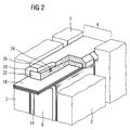
- the groove 4 of a laminated core 2 of a generator stand is shown in cross section.
- two winding rods 6 are positioned.
- These two winding bars 6 are constructed equal to each other and consist of staggered arranged solid conductors 8 and corresponding waveguide 10 for cooling the winding.
- the individual conductor planes are separated from each other by a layer insulation 12 and enclosed in total by an insulation 14.
- a Nut typicallylage 16 is provided, while the groove 4 is closed at the upper end by a keying.
- a slot closure spring 18 is disposed above the overhead winding bar 6, which is designed as a longitudinally corrugated leaf spring.
- a combination of a deck key 20 and a drive key 22 is used which are positioned and solidified in recesses of the side walls of the keyway 4.
- the deck key 20 is inserted into the recesses of the groove 4 and then pushed the drive key 22 between NutverBankfeder 18 and deck wedge 20 and then driven.
- deck wedge 20 and drive wedge 22 positioned with their rising wedge surfaces against each other, so that when driving or solidifying the drive wedge 22 already a slight shift to a significant broadening of the combination of deck wedge 20 and driving wedge 22 with respect to the NutausEnglishept the groove 4 leads.
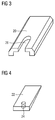
- the cover wedge 20 and in FIG. 4 the drive wedge 22 are shown in greater detail.
- the deck wedge 20 is made of cotton hard fabric and the driving wedge 22 is made of hard glass cloth.
- the deck key 20 and the drive key 22 is designed for Nachverkeilung with built-generator rotor.
- the drive wedge 22 has a bore 24 at the outer end. In this can be intervened with a steel pin attached to an aluminum rod and the driving wedge 22 driven or post-solidified. The aluminum rod is guided through the air gap between the laminated core 2 of the stator and the generator rotor to the respective groove 4 to be wedged.
- the steel pin is then passed through the slot 26 of the deck key 20 in the bore 24 of the drive wedge 22.
- the slot 26 of the deck wedge 20 and the bore 24 of the drive wedge have the same diameter.
- Through the slot 26 in the deck wedge 20 of the engaging steel pin can reinforce the drive wedge 22, wherein the deck wedge 20 remains fixed in position and the pin can move with the drive wedge 22 in the slot 26.
Landscapes
- Engineering & Computer Science (AREA)
- Power Engineering (AREA)
- Insulation, Fastening Of Motor, Generator Windings (AREA)
- Manufacture Of Motors, Generators (AREA)
Priority Applications (1)
| Application Number | Priority Date | Filing Date | Title |
|---|---|---|---|
| EP04021943A EP1638190A1 (fr) | 2004-09-15 | 2004-09-15 | Dispositif pour fixer des barres conductrices dans les encoches des machines électriques |
Applications Claiming Priority (1)
| Application Number | Priority Date | Filing Date | Title |
|---|---|---|---|
| EP04021943A EP1638190A1 (fr) | 2004-09-15 | 2004-09-15 | Dispositif pour fixer des barres conductrices dans les encoches des machines électriques |
Publications (1)
| Publication Number | Publication Date |
|---|---|
| EP1638190A1 true EP1638190A1 (fr) | 2006-03-22 |
Family
ID=34926550
Family Applications (1)
| Application Number | Title | Priority Date | Filing Date |
|---|---|---|---|
| EP04021943A Withdrawn EP1638190A1 (fr) | 2004-09-15 | 2004-09-15 | Dispositif pour fixer des barres conductrices dans les encoches des machines électriques |
Country Status (1)
| Country | Link |
|---|---|
| EP (1) | EP1638190A1 (fr) |
Cited By (5)
| Publication number | Priority date | Publication date | Assignee | Title |
|---|---|---|---|---|
| EP2523310A3 (fr) * | 2011-05-09 | 2017-05-03 | General Electric Company | Procédé et kit pour l'amélioration de générateur |
| CN108667232A (zh) * | 2018-07-11 | 2018-10-16 | 株洲电力机车广缘科技有限责任公司 | 一种电机槽楔模压工艺中的卷料棒及该电机槽楔模压工艺 |
| EP3534500A1 (fr) * | 2018-03-01 | 2019-09-04 | Moteurs Leroy-Somer | Rotor ou stator bobine et procede de fabrication |
| WO2024104753A1 (fr) * | 2022-11-16 | 2024-05-23 | Bayerische Motoren Werke Aktiengesellschaft | Composant de bobine pour une machine électrique d'un véhicule automobile et procédé de fabrication d'un composant de bobine |
| WO2025180735A1 (fr) * | 2024-02-27 | 2025-09-04 | Siemens Energy Global GmbH & Co. KG | Agencement de bandes pour supporter mutuellement deux composants disposés l'un à l'intérieur de l'autre |
Citations (5)
| Publication number | Priority date | Publication date | Assignee | Title |
|---|---|---|---|---|
| DE2656373A1 (de) * | 1976-12-13 | 1978-06-15 | Chutorezkij | Stator einer elektrischen maschine |
| SU744849A2 (ru) * | 1978-03-28 | 1980-06-30 | Предприятие П/Я А-7376 | Устройство дл закреплени обмотки в пазах статора электрической машины |
| JPH1189151A (ja) * | 1997-09-08 | 1999-03-30 | Hitachi Ltd | 回転電機 |
| DE19742900A1 (de) * | 1997-09-29 | 1999-04-01 | Asea Brown Boveri | Nutverschlußanordnung |
| US6294855B1 (en) * | 1999-12-03 | 2001-09-25 | General Electric Co. | Generator stator slot wedge system that can be adjusted in situ to provide increased radial load |
-
2004
- 2004-09-15 EP EP04021943A patent/EP1638190A1/fr not_active Withdrawn
Patent Citations (5)
| Publication number | Priority date | Publication date | Assignee | Title |
|---|---|---|---|---|
| DE2656373A1 (de) * | 1976-12-13 | 1978-06-15 | Chutorezkij | Stator einer elektrischen maschine |
| SU744849A2 (ru) * | 1978-03-28 | 1980-06-30 | Предприятие П/Я А-7376 | Устройство дл закреплени обмотки в пазах статора электрической машины |
| JPH1189151A (ja) * | 1997-09-08 | 1999-03-30 | Hitachi Ltd | 回転電機 |
| DE19742900A1 (de) * | 1997-09-29 | 1999-04-01 | Asea Brown Boveri | Nutverschlußanordnung |
| US6294855B1 (en) * | 1999-12-03 | 2001-09-25 | General Electric Co. | Generator stator slot wedge system that can be adjusted in situ to provide increased radial load |
Non-Patent Citations (2)
| Title |
|---|
| DATABASE WPI Section EI Week 198112, Derwent World Patents Index; Class V06, AN 1981-C5151D, XP002319652 * |
| PATENT ABSTRACTS OF JAPAN vol. 1999, no. 08 30 June 1999 (1999-06-30) * |
Cited By (9)
| Publication number | Priority date | Publication date | Assignee | Title |
|---|---|---|---|---|
| EP2523310A3 (fr) * | 2011-05-09 | 2017-05-03 | General Electric Company | Procédé et kit pour l'amélioration de générateur |
| US9680343B2 (en) | 2011-05-09 | 2017-06-13 | General Electric Company | Method and kit for upgrading a generator to enhance operation of the generator |
| EP3534500A1 (fr) * | 2018-03-01 | 2019-09-04 | Moteurs Leroy-Somer | Rotor ou stator bobine et procede de fabrication |
| FR3078585A1 (fr) * | 2018-03-01 | 2019-09-06 | Moteurs Leroy-Somer | Rotor ou stator bobine et procede de fabrication |
| US11081944B2 (en) | 2018-03-01 | 2021-08-03 | Moteurs Leroy-Somer | Wound rotor or stator and method for manufacturing same |
| CN108667232A (zh) * | 2018-07-11 | 2018-10-16 | 株洲电力机车广缘科技有限责任公司 | 一种电机槽楔模压工艺中的卷料棒及该电机槽楔模压工艺 |
| CN108667232B (zh) * | 2018-07-11 | 2024-01-30 | 株洲电力机车广缘科技有限责任公司 | 一种电机槽楔模压工艺中的卷料棒及该电机槽楔模压工艺 |
| WO2024104753A1 (fr) * | 2022-11-16 | 2024-05-23 | Bayerische Motoren Werke Aktiengesellschaft | Composant de bobine pour une machine électrique d'un véhicule automobile et procédé de fabrication d'un composant de bobine |
| WO2025180735A1 (fr) * | 2024-02-27 | 2025-09-04 | Siemens Energy Global GmbH & Co. KG | Agencement de bandes pour supporter mutuellement deux composants disposés l'un à l'intérieur de l'autre |
Similar Documents
| Publication | Publication Date | Title |
|---|---|---|
| DE69931011T2 (de) | Rotierende maschine wie zum beispiel drehstromgenerator für kraftfahrzeuge | |
| DE60024626T2 (de) | Rotor für Permanentmagnet-Typ drehende Maschine | |
| DE69600160T2 (de) | Anker für eine Reluktanzmaschine | |
| EP1166423B1 (fr) | Rotor multipolaire a aimants permanents pour machine tournante electrique et procede de fabrication associe | |
| DE10220822B4 (de) | Linearmotor | |
| DE3135924A1 (de) | Dynamoelektrische maschine mit permanentmagnetrotor | |
| DE2934318A1 (de) | Rotor einer elektrischen maschine | |
| WO2002089291A2 (fr) | Machine synchrone electrique a enroulement toroidal | |
| EP3180836A1 (fr) | Machine électrique à faibles fuites magnétiques au niveau de rainures | |
| DE102020124860A1 (de) | Rotor für fremderregte Synchronmaschine sowie fremderregte Synchronmaschine | |
| DE69716729T2 (de) | Wicklung für den stator einer rotierenden elektrischen maschine sowie eine derartige maschine | |
| DE3885477T2 (de) | Zahnflankenkonstruktion eines Stators in einer elektro-dynamischen Maschine. | |
| EP3048702A1 (fr) | Rotor d'une machine à reluctance | |
| EP0748030A2 (fr) | Dispositif pour l'introduction de cales d'encoche pour machines électriques tournantes | |
| EP2122812A1 (fr) | Actionneur linéaire | |
| DE3308005A1 (de) | Rotierende elektromaschine mit luftspaltwicklung | |
| WO2019149508A1 (fr) | Rotor comprenant des conduits de refroidissement | |
| DE3308006C2 (de) | Rotierende Elektromaschine mit Luftspaltwicklung | |
| WO2017153061A1 (fr) | Machine électrique à constance de régime élevée | |
| DE102019105570A1 (de) | Rotor für eine permanenterregte elektrische Maschine mit Stützstruktur | |
| DE3003483A1 (de) | Anordnung zur befestigung einer luftspaltwicklung im staender einer elektrischen maschine | |
| EP0926800A2 (fr) | TÔle statorique pour machine électrique | |
| DE1958501A1 (de) | Hochleistungsmotor | |
| DE3145804C2 (de) | Rotor für einen Turbogenerator | |
| DE102005046165A1 (de) | Sekundärteil einer permanentmagneterregten Synchronmaschine |
Legal Events
| Date | Code | Title | Description |
|---|---|---|---|
| PUAI | Public reference made under article 153(3) epc to a published international application that has entered the european phase |
Free format text: ORIGINAL CODE: 0009012 |
|
| AK | Designated contracting states |
Kind code of ref document: A1 Designated state(s): AT BE BG CH CY CZ DE DK EE ES FI FR GB GR HU IE IT LI LU MC NL PL PT RO SE SI SK TR |
|
| AX | Request for extension of the european patent |
Extension state: AL HR LT LV MK |
|
| 17P | Request for examination filed |
Effective date: 20060421 |
|
| AKX | Designation fees paid |
Designated state(s): AT BE BG CH CY CZ DE DK EE ES FI FR GB GR HU IE IT LI LU MC NL PL PT RO SE SI SK TR |
|
| 17Q | First examination report despatched |
Effective date: 20060614 |
|
| STAA | Information on the status of an ep patent application or granted ep patent |
Free format text: STATUS: THE APPLICATION IS DEEMED TO BE WITHDRAWN |
|
| 18D | Application deemed to be withdrawn |
Effective date: 20070612 |