EP1638201A2 - Elektronische Vorrichtung zur Steuerung einer Austragspumpe durch ein Synchronmotor mit Permanentmagnet-Rotor - Google Patents
Elektronische Vorrichtung zur Steuerung einer Austragspumpe durch ein Synchronmotor mit Permanentmagnet-Rotor Download PDFInfo
- Publication number
- EP1638201A2 EP1638201A2 EP05023243A EP05023243A EP1638201A2 EP 1638201 A2 EP1638201 A2 EP 1638201A2 EP 05023243 A EP05023243 A EP 05023243A EP 05023243 A EP05023243 A EP 05023243A EP 1638201 A2 EP1638201 A2 EP 1638201A2
- Authority
- EP
- European Patent Office
- Prior art keywords
- motor
- current
- phase shift
- pump
- measuring
- Prior art date
- Legal status (The legal status is an assumption and is not a legal conclusion. Google has not performed a legal analysis and makes no representation as to the accuracy of the status listed.)
- Granted
Links
Images


Classifications
-
- H—ELECTRICITY
- H02—GENERATION; CONVERSION OR DISTRIBUTION OF ELECTRIC POWER
- H02P—CONTROL OR REGULATION OF ELECTRIC MOTORS, ELECTRIC GENERATORS OR DYNAMO-ELECTRIC CONVERTERS; CONTROLLING TRANSFORMERS, REACTORS OR CHOKE COILS
- H02P27/00—Arrangements or methods for the control of AC motors characterised by the kind of supply voltage
- H02P27/02—Arrangements or methods for the control of AC motors characterised by the kind of supply voltage using supply voltage with constant frequency and variable amplitude
-
- F—MECHANICAL ENGINEERING; LIGHTING; HEATING; WEAPONS; BLASTING
- F04—POSITIVE - DISPLACEMENT MACHINES FOR LIQUIDS; PUMPS FOR LIQUIDS OR ELASTIC FLUIDS
- F04D—NON-POSITIVE-DISPLACEMENT PUMPS
- F04D15/00—Control, e.g. regulation, of pumps, pumping installations or systems
- F04D15/0066—Control, e.g. regulation, of pumps, pumping installations or systems by changing the speed, e.g. of the driving engine
-
- H—ELECTRICITY
- H02—GENERATION; CONVERSION OR DISTRIBUTION OF ELECTRIC POWER
- H02P—CONTROL OR REGULATION OF ELECTRIC MOTORS, ELECTRIC GENERATORS OR DYNAMO-ELECTRIC CONVERTERS; CONTROLLING TRANSFORMERS, REACTORS OR CHOKE COILS
- H02P25/00—Arrangements or methods for the control of AC motors characterised by the kind of AC motor or by structural details
- H02P25/02—Arrangements or methods for the control of AC motors characterised by the kind of AC motor or by structural details characterised by the kind of motor
- H02P25/022—Synchronous motors
- H02P25/024—Synchronous motors controlled by supply frequency
Definitions
- the present invention relates, in its more general aspect, to a synchronous discharge pump, i.e. a pump driven by a synchronous electric motor with a permanent-magnet rotor, particularly of the type incorporated in a household appliance.
- the invention relates to a method for controlling and driving a pump for household appliances driven by a synchronous electric motor including a permanent-magnet rotor and associated to an electronic controller receiving at its input a synchronizing signal of the motor supply voltage and at least a second signal being proportional to the current supplied to the motor.
- the invention further relates to an electronic device for controlling and driving a pump for household appliances driven by a synchronous electric motor including a permanent-magnet rotor, said device including an electronic controller receiving at its input a synchronizing signal of the motor supply voltage and at least a second signal being proportional to the current supplied to the motor.
- discharge pumps are operated for a predetermined time, discharging liquids as well as air and foaming agents.
- the discharge pump can operate sucking an air-water mixture.
- the problem underlying the present invention is to provide a method and an electronic device for controlling and driving a synchronous pump, particularly for household appliances, having such structural and functional features as to allow all the drawbacks mentioned with reference to the prior art to be overcome in a simple and inexpensive way.
- a synchronous pump can operate sucking an air-water mixture and during such a period of time wherein this kind of operation occurs the noise produced by the pump considerably increases.
- the electronic control device driving the pump may interrupt the pump operation by interrupting the synchronous electric motor operation for a short period.
- This short interruption period may be predetermined and may depend on the household appliance wherein the pump is installed.
- the interruption can last even a few seconds, after which the pump is restarted assuming that, in the meantime, a valuable amount of liquid has been accumulated, which is sufficient to avoid the partial-load operation, which is noisy and also unstable.
- the electronic control device of the present invention is capable of recognising the air-water operating state and, consequently, it is capable of interrupting the pump operation.
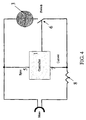
- Figure 1 schematically shows a first embodiment of an electronic device showing how the synchronous motor starting step is regulated according to a network synchronizing signal and a signal provided by a Hall-effect rotor position sensor.
- an electronic control device receives at its input a signal 4 coming from a rotor position sensor 2 of the motor 3, and a network synchronizing signal 5.
- the controller 1 drives a static power switch 6, for example a TRIAC being serially connected to one of the stator windings.
- the position sensor 2 which in the case of a permanent-magnet synchronous motor can be very conveniently a Hall-effect sensor, provides an angle coinciding, except for a constant, with the load angle ⁇ .
- the passage of the rotor magnetic flux peak can be measured. Knowing that the latter is delayed by 90° with respect to the counter electromotive force, the load angle ⁇ can be precisely determined as phase shift between the voltage applied to the motor 3 terminals. This voltage is known by means of the network synchronizing signal S.
- the load angle ⁇ is thus determined by the controller 1 taking as reference the network synchronizing signal 5 which is a square wave signal, with rising and falling edges coinciding with the supply voltage zero-crossing.
- Figures 2 and 3 show two vector diagrams of the voltage V, of the current I and of the counter electromotive force E, related to two different operating conditions wherein the load angle ⁇ is different.
- Figure 2 schematically shows a vector diagram allowing a better understanding of the calculations performed in the controller 1.
- Figure 3 shows the same diagram but related to a different operating condition with a different load angle.
- the different operating modes to be identified are very distinct; for example, regular full load operation and air-water operation, to be thus able to turn the pump off in the latter case to avoid useless noises.
- phase shift angle ⁇ between the Sync signal 5 and a Current signal 7, conveniently adopted and squared off, is measured by means of a sensor 8.
- the controller 1 Being it possible to equip the controller 1 with logic and/or calculation means, it is advisable to compare the measuring stability of said phase shift in a convenient time period so that is an index of a stable full load pump operation or, in case of a possible instability, it's an index of a sure air-water pump operation.
- the pump operates in a silent way and with full load and it is turned off when a certain amount of air is accumulated in the pump coil; after a certain time, when the water amount is sufficient to discharge in a stable and silent way, the pump is restarted.
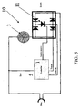
- FIG. 10 Another electronic device manufactured in accordance with the present invention is provided for controlling a discharge pump 15 driven by a permanent-magnet synchronous electric motor 3 and incorporated in a household appliance (not shown in the figures).
- This electronic device is described in detail hereinafter and globally indicated with 10.
- the device 10 comprises at least a controller 1 receiving at its input a synchronizing signal 5 of the supply network voltage V of the motor 3 and at least a second signal 7 being proportional to the current absorbed by the motor, to drive at its output a switch 6 being series-connected to one of the motor windings.
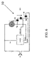
- the switch 6 is manufactured with a bidirectional switch, particularly a device 11 comprising a four-diode bridge.
- the Triac 6 is replaced by a bidirectional switch, for example an SCR device as central element of a power-diode bridge.
- the SCR device 11 has advantageously an overall cost being lower or equal to another kind of switch, but it also offers the possibility of having a univocal and clear current zero crossing signal, thus avoiding complex and/or highly amplified signal regulation blocks, which are then more delicate from the point of view of noises, as in prior art devices.
- V a ⁇ V b V d + V scr
- Vd is the drop by direct conduction of one of the bridge diodes
- Vscr is the drop by SCR direct conduction.
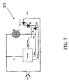
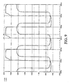
- the diagrams of figures 8 and 9 show the graphs of the quantities network Voltage, Current and corresponding values SYNC (squared network voltage) and Current (just described Va - Vb).
- the amplitudes of these signals can be directly processed by low voltage logics being available on the market (1.8 V).
- the square wave value of the Current signal 7 with positive sense current can be greater by adding in series a convenient resistance or another junction, according to the needs.
- the main advantage achieved by the electronic device according to the present invention is its unusual simplicity, reliability and extremely low cost
- the switch 11 is not a Triac and then the application must not undergo a failure test of the "diode mode" type.
- the device 11 is suitable for being monolithically manufactured together with the controller 1 as integrated circuit with control pins directly connecting to the motor. In this case short-circuit or open-circuit failure tests could be performed; both situations would not be however dangerous since the motor would run or would be blocked according to the case, without power crossing.
- the thermal protection could be even removed if also the "blocked rotor" failure test could be controlled: in this case the controller 1 can detect the rotor blocked through the phase shift between voltage and current, then through the anomalous phase shift between the SYNC and Current signals 5 and 7, with blocked rotor.
- the controller 1 could acquire the dangerous state and stop the supply.
- a housing and supplying board 18 of the device 11 can be provided in a recess formed between two motor windings.
- the thermal sensor could be housed on the opposite side with respect to the device 11, ensuring however a sufficient pump thermal protection.
- controller 1 is an arithmetical-logic integrated circuit, it is also possible to exploit the calculation capability thereof to perform redundant controls to ensure the operating safety.
- the electronic device 10 for controlling a synchronous discharge pump as previously described can undergo some modifications, all within the reach of the skilled in the art and failing within the scope of protection of the present invention, as defined in the following claims.
Landscapes
- Engineering & Computer Science (AREA)
- Power Engineering (AREA)
- Mechanical Engineering (AREA)
- General Engineering & Computer Science (AREA)
- Control Of Ac Motors In General (AREA)
- Control Of Motors That Do Not Use Commutators (AREA)
- Control Of Positive-Displacement Pumps (AREA)
- Lubrication Of Internal Combustion Engines (AREA)
Priority Applications (2)
| Application Number | Priority Date | Filing Date | Title |
|---|---|---|---|
| DE60327111T DE60327111D1 (de) | 2003-10-07 | 2003-10-07 | Elektronische Vorrichtung zur Steuerung einer Austragspumpe durch ein Synchronmotor mit Permanentmagnet-Rotor |
| DE20321134U DE20321134U1 (de) | 2003-10-07 | 2003-10-07 | Elektronische Vorrichtung zum Steuern und Antreiben einer Pumpe für Haushaltsgeräte |
Applications Claiming Priority (1)
| Application Number | Priority Date | Filing Date | Title |
|---|---|---|---|
| EP03425653A EP1524760B1 (de) | 2003-10-07 | 2003-10-07 | Elektronische Vorrichtung zur Steuerung einer Austragspumpe durch ein Synchronmotor mit Permanentmagnet-Rotor |
Related Parent Applications (1)
| Application Number | Title | Priority Date | Filing Date |
|---|---|---|---|
| EP03425653A Division EP1524760B1 (de) | 2003-10-07 | 2003-10-07 | Elektronische Vorrichtung zur Steuerung einer Austragspumpe durch ein Synchronmotor mit Permanentmagnet-Rotor |
Publications (3)
| Publication Number | Publication Date |
|---|---|
| EP1638201A2 true EP1638201A2 (de) | 2006-03-22 |
| EP1638201A3 EP1638201A3 (de) | 2006-05-31 |
| EP1638201B1 EP1638201B1 (de) | 2009-04-08 |
Family
ID=34354642
Family Applications (2)
| Application Number | Title | Priority Date | Filing Date |
|---|---|---|---|
| EP05023243A Expired - Lifetime EP1638201B1 (de) | 2003-10-07 | 2003-10-07 | Elektronische Vorrichtung zur Steuerung einer Austragspumpe durch ein Synchronmotor mit Permanentmagnet-Rotor |
| EP03425653A Expired - Lifetime EP1524760B1 (de) | 2003-10-07 | 2003-10-07 | Elektronische Vorrichtung zur Steuerung einer Austragspumpe durch ein Synchronmotor mit Permanentmagnet-Rotor |
Family Applications After (1)
| Application Number | Title | Priority Date | Filing Date |
|---|---|---|---|
| EP03425653A Expired - Lifetime EP1524760B1 (de) | 2003-10-07 | 2003-10-07 | Elektronische Vorrichtung zur Steuerung einer Austragspumpe durch ein Synchronmotor mit Permanentmagnet-Rotor |
Country Status (5)
| Country | Link |
|---|---|
| US (1) | US7068008B2 (de) |
| EP (2) | EP1638201B1 (de) |
| AT (2) | ATE536478T1 (de) |
| DE (2) | DE60327111D1 (de) |
| ES (2) | ES2324997T3 (de) |
Cited By (2)
| Publication number | Priority date | Publication date | Assignee | Title |
|---|---|---|---|---|
| RU2687175C1 (ru) * | 2018-06-18 | 2019-05-07 | федеральное государственное автономное образовательное учреждение высшего образования "Южно-Уральский государственный университет (национальный исследовательский университет)" | Система регулирования электропривода насосного агрегата и способ работы системы |
| DE102008029910C5 (de) * | 2008-06-24 | 2020-03-05 | BSH Hausgeräte GmbH | Verfahren zur Lastzustandserkennung einer Pumpe |
Families Citing this family (7)
| Publication number | Priority date | Publication date | Assignee | Title |
|---|---|---|---|---|
| EP1783264A3 (de) * | 2005-11-04 | 2008-10-15 | Fisher & Paykel Appliances Ltd. | Verbesserungen in Bezug auf die Waschmaschinen |
| PL2428608T3 (pl) * | 2010-09-14 | 2013-04-30 | Miele & Cie | Sposób sterowania pompą w pralce, system mechatroniczny i pralka |
| DE102010042494A1 (de) * | 2010-10-15 | 2012-04-19 | BSH Bosch und Siemens Hausgeräte GmbH | Verfahren zum Abschalten eines Einphasen-Synchronmotors, Schaltungsanordnung zum Betreiben eines Einphasen-Synchronmotors und Hausgerät |
| ITTO20110413A1 (it) * | 2011-05-11 | 2012-11-12 | Amc S N C Di Ruscello Lorenzo & C | Disposizione circuitale per la rivelazione del carico applicato ad un motore elettrico sulla base dell'angolo di sfasamento tra le grandezze elettriche del motore |
| CN106133229A (zh) * | 2013-11-29 | 2016-11-16 | 阿塞里克股份有限公司 | 家用电器排水泵及其控制电路 |
| DE102014103472A1 (de) | 2014-03-14 | 2015-09-17 | Miele & Cie. Kg | Pumpeinrichtung für ein wasserführendes Gerät und wasserführendes Gerät |
| CN107482760B (zh) * | 2016-06-08 | 2020-06-30 | 光宝电子(广州)有限公司 | 开关装置 |
Family Cites Families (12)
| Publication number | Priority date | Publication date | Assignee | Title |
|---|---|---|---|---|
| CH524709A (de) * | 1971-03-02 | 1972-06-30 | Holzer Patent Ag | Anordnung mit einem Regelkreis, einem Motor und einem zusätzlichen elektrischen Heizwiderstand |
| US3908158A (en) * | 1973-05-09 | 1975-09-23 | Borg Warner | Control system for adjusting a-c motor speed at line frequency or a subharmonic of the line frequency |
| US4806838A (en) * | 1988-05-23 | 1989-02-21 | Weber Harold J | A.C. induction motor energy conserving power control method and apparatus |
| IT1259115B (it) * | 1992-06-17 | 1996-03-11 | Askoll Spa | Dispositivo elettronico per l'avviamento di un motore sincrono con rotore a magnete permanente |
| FR2706228B1 (fr) * | 1993-06-08 | 1995-08-11 | Salmson Pompes | Procédé et dispositif de régulation de l'alimentation d'un moteur électrique asynchrone. |
| JP3555297B2 (ja) * | 1996-02-06 | 2004-08-18 | 松下電器産業株式会社 | 動力発生装置及びその応用機器たる掃除機 |
| TR199700528A2 (xx) * | 1997-06-20 | 1999-10-21 | Ar�El�K A.�. | Elektrikli ev aletlerinde kullan�lan tahliye pompalar� i�in elektronik kontrol y�ntemi. |
| DE19815232A1 (de) * | 1998-04-04 | 1999-10-07 | Grundfos As | Verfahren zur Erfassung eines Parameters eines Asynchronmotors |
| JP2001078446A (ja) * | 1999-06-29 | 2001-03-23 | Toshiba Corp | 電源装置 |
| DE10014665B4 (de) * | 2000-03-24 | 2005-09-22 | Siemens Ag | Verfahren zum Schutz eines Matrixumrichters vor Überspannungen und eine aktive Überspannungsvorrichtung |
| DE10014641C2 (de) * | 2000-03-24 | 2002-03-07 | Siemens Ag | Schaltungsanordnung mit einem bidirektionalen Leistungsschalter in Common Kollektor Mode und mit einer aktiven Überspannungsschutzvorrichtung |
| GB2396441B (en) * | 2002-12-20 | 2005-11-30 | Motorola Inc | Circuit and method for supplying an electrical a.c. load |
-
2003
- 2003-10-07 ES ES05023243T patent/ES2324997T3/es not_active Expired - Lifetime
- 2003-10-07 AT AT03425653T patent/ATE536478T1/de active
- 2003-10-07 ES ES03425653T patent/ES2378661T3/es not_active Expired - Lifetime
- 2003-10-07 DE DE60327111T patent/DE60327111D1/de not_active Expired - Lifetime
- 2003-10-07 DE DE20321134U patent/DE20321134U1/de not_active Expired - Lifetime
- 2003-10-07 EP EP05023243A patent/EP1638201B1/de not_active Expired - Lifetime
- 2003-10-07 AT AT05023243T patent/ATE428216T1/de not_active IP Right Cessation
- 2003-10-07 EP EP03425653A patent/EP1524760B1/de not_active Expired - Lifetime
-
2004
- 2004-10-06 US US10/959,761 patent/US7068008B2/en not_active Expired - Lifetime
Cited By (2)
| Publication number | Priority date | Publication date | Assignee | Title |
|---|---|---|---|---|
| DE102008029910C5 (de) * | 2008-06-24 | 2020-03-05 | BSH Hausgeräte GmbH | Verfahren zur Lastzustandserkennung einer Pumpe |
| RU2687175C1 (ru) * | 2018-06-18 | 2019-05-07 | федеральное государственное автономное образовательное учреждение высшего образования "Южно-Уральский государственный университет (национальный исследовательский университет)" | Система регулирования электропривода насосного агрегата и способ работы системы |
Also Published As
| Publication number | Publication date |
|---|---|
| EP1638201B1 (de) | 2009-04-08 |
| EP1524760A1 (de) | 2005-04-20 |
| ES2378661T3 (es) | 2012-04-16 |
| US7068008B2 (en) | 2006-06-27 |
| EP1524760B1 (de) | 2011-12-07 |
| EP1638201A3 (de) | 2006-05-31 |
| US20050073278A1 (en) | 2005-04-07 |
| DE20321134U1 (de) | 2006-08-03 |
| ATE428216T1 (de) | 2009-04-15 |
| DE60327111D1 (de) | 2009-05-20 |
| ATE536478T1 (de) | 2011-12-15 |
| ES2324997T3 (es) | 2009-08-21 |
Similar Documents
| Publication | Publication Date | Title |
|---|---|---|
| CN102769428A (zh) | 具备绝缘劣化检测装置的电机控制装置及电机的绝缘劣化检测方法 | |
| CA2204970A1 (en) | Microprocessor based motor control system with phase difference detection | |
| EP1638201B1 (de) | Elektronische Vorrichtung zur Steuerung einer Austragspumpe durch ein Synchronmotor mit Permanentmagnet-Rotor | |
| WO2006106654A1 (ja) | インバータ装置 | |
| US20070040532A1 (en) | Motor controller and control method thereof, and error detecting apparatus of inverter | |
| KR101523793B1 (ko) | 동기식 전기 모터의 정상-상태 회전 제어를 위한 시스템 | |
| JP4539237B2 (ja) | インバータ装置 | |
| JP5228387B2 (ja) | インバータ装置 | |
| US9019675B2 (en) | Method and structure for detecting an overcurrent in a triac | |
| JP4788603B2 (ja) | インバータ装置 | |
| CN1122435A (zh) | 空调器控制装置及其方法 | |
| KR101039435B1 (ko) | 전동기의 제어 장치 및 방법 | |
| JP2009189202A (ja) | 電力変換装置、ブラシレスdcモータおよび換気送風装置 | |
| KR100936019B1 (ko) | 트레드밀의 모터 구동 장치 및 방법 | |
| JP2004260943A (ja) | 可変速電動機の運転制御装置およびその運転制御方法 | |
| US12483179B2 (en) | Methods and circuits for cross conduction protection in an electric motor | |
| US20250112564A1 (en) | Control Circuits for Disposer Motors | |
| KR102159110B1 (ko) | 차량용 모터 구동장치 | |
| CN209462288U (zh) | 一种无霍尔元件的无刷电机控制电路 | |
| KR20170017823A (ko) | 자기 센서 및 자기 센서의 동작 상태를 제어하는 방법 | |
| KR20090004004A (ko) | 삼상유도전동기의 리액터식 절전구동장치 | |
| KR20170017818A (ko) | 자기 센서, 집적 회로 및 모터 어셈블리 | |
| KR200176995Y1 (ko) | 전류감지 스위치 | |
| KR100825158B1 (ko) | 회전 전기의 정수 측정 방법 | |
| JP2004293321A (ja) | 水位センサレスポンプの渇水運転防止方法および装置 |
Legal Events
| Date | Code | Title | Description |
|---|---|---|---|
| PUAI | Public reference made under article 153(3) epc to a published international application that has entered the european phase |
Free format text: ORIGINAL CODE: 0009012 |
|
| AC | Divisional application: reference to earlier application |
Ref document number: 1524760 Country of ref document: EP Kind code of ref document: P |
|
| AK | Designated contracting states |
Kind code of ref document: A2 Designated state(s): AT BE BG CH CY CZ DE DK EE ES FI FR GB GR HU IE IT LI LU MC NL PT RO SE SI SK TR |
|
| AX | Request for extension of the european patent |
Extension state: AL LT LV MK |
|
| PUAL | Search report despatched |
Free format text: ORIGINAL CODE: 0009013 |
|
| AK | Designated contracting states |
Kind code of ref document: A3 Designated state(s): AT BE BG CH CY CZ DE DK EE ES FI FR GB GR HU IE IT LI LU MC NL PT RO SE SI SK TR |
|
| AX | Request for extension of the european patent |
Extension state: AL LT LV MK |
|
| 17P | Request for examination filed |
Effective date: 20061129 |
|
| AKX | Designation fees paid |
Designated state(s): AT BE BG CH CY CZ DE DK EE ES FI FR GB GR HU IE IT LI LU MC NL PT RO SE SI SK TR |
|
| 17Q | First examination report despatched |
Effective date: 20070209 |
|
| GRAP | Despatch of communication of intention to grant a patent |
Free format text: ORIGINAL CODE: EPIDOSNIGR1 |
|
| GRAS | Grant fee paid |
Free format text: ORIGINAL CODE: EPIDOSNIGR3 |
|
| GRAA | (expected) grant |
Free format text: ORIGINAL CODE: 0009210 |
|
| AC | Divisional application: reference to earlier application |
Ref document number: 1524760 Country of ref document: EP Kind code of ref document: P |
|
| AK | Designated contracting states |
Kind code of ref document: B1 Designated state(s): AT BE BG CH CY CZ DE DK EE ES FI FR GB GR HU IE IT LI LU MC NL PT RO SE SI SK TR |
|
| REG | Reference to a national code |
Ref country code: GB Ref legal event code: FG4D |
|
| REG | Reference to a national code |
Ref country code: CH Ref legal event code: EP |
|
| REG | Reference to a national code |
Ref country code: IE Ref legal event code: FG4D |
|
| REF | Corresponds to: |
Ref document number: 60327111 Country of ref document: DE Date of ref document: 20090520 Kind code of ref document: P |
|
| PG25 | Lapsed in a contracting state [announced via postgrant information from national office to epo] |
Ref country code: SI Free format text: LAPSE BECAUSE OF FAILURE TO SUBMIT A TRANSLATION OF THE DESCRIPTION OR TO PAY THE FEE WITHIN THE PRESCRIBED TIME-LIMIT Effective date: 20090408 |
|
| REG | Reference to a national code |
Ref country code: ES Ref legal event code: FG2A Ref document number: 2324997 Country of ref document: ES Kind code of ref document: T3 |
|
| NLV1 | Nl: lapsed or annulled due to failure to fulfill the requirements of art. 29p and 29m of the patents act | ||
| PG25 | Lapsed in a contracting state [announced via postgrant information from national office to epo] |
Ref country code: PT Free format text: LAPSE BECAUSE OF FAILURE TO SUBMIT A TRANSLATION OF THE DESCRIPTION OR TO PAY THE FEE WITHIN THE PRESCRIBED TIME-LIMIT Effective date: 20090908 Ref country code: AT Free format text: LAPSE BECAUSE OF FAILURE TO SUBMIT A TRANSLATION OF THE DESCRIPTION OR TO PAY THE FEE WITHIN THE PRESCRIBED TIME-LIMIT Effective date: 20090408 |
|
| PG25 | Lapsed in a contracting state [announced via postgrant information from national office to epo] |
Ref country code: SE Free format text: LAPSE BECAUSE OF FAILURE TO SUBMIT A TRANSLATION OF THE DESCRIPTION OR TO PAY THE FEE WITHIN THE PRESCRIBED TIME-LIMIT Effective date: 20090708 Ref country code: NL Free format text: LAPSE BECAUSE OF FAILURE TO SUBMIT A TRANSLATION OF THE DESCRIPTION OR TO PAY THE FEE WITHIN THE PRESCRIBED TIME-LIMIT Effective date: 20090408 |
|
| PG25 | Lapsed in a contracting state [announced via postgrant information from national office to epo] |
Ref country code: RO Free format text: LAPSE BECAUSE OF FAILURE TO SUBMIT A TRANSLATION OF THE DESCRIPTION OR TO PAY THE FEE WITHIN THE PRESCRIBED TIME-LIMIT Effective date: 20090408 Ref country code: DK Free format text: LAPSE BECAUSE OF FAILURE TO SUBMIT A TRANSLATION OF THE DESCRIPTION OR TO PAY THE FEE WITHIN THE PRESCRIBED TIME-LIMIT Effective date: 20090408 Ref country code: EE Free format text: LAPSE BECAUSE OF FAILURE TO SUBMIT A TRANSLATION OF THE DESCRIPTION OR TO PAY THE FEE WITHIN THE PRESCRIBED TIME-LIMIT Effective date: 20090408 |
|
| PLBE | No opposition filed within time limit |
Free format text: ORIGINAL CODE: 0009261 |
|
| STAA | Information on the status of an ep patent application or granted ep patent |
Free format text: STATUS: NO OPPOSITION FILED WITHIN TIME LIMIT |
|
| PG25 | Lapsed in a contracting state [announced via postgrant information from national office to epo] |
Ref country code: BE Free format text: LAPSE BECAUSE OF FAILURE TO SUBMIT A TRANSLATION OF THE DESCRIPTION OR TO PAY THE FEE WITHIN THE PRESCRIBED TIME-LIMIT Effective date: 20090408 Ref country code: SK Free format text: LAPSE BECAUSE OF FAILURE TO SUBMIT A TRANSLATION OF THE DESCRIPTION OR TO PAY THE FEE WITHIN THE PRESCRIBED TIME-LIMIT Effective date: 20090408 |
|
| 26N | No opposition filed |
Effective date: 20100111 |
|
| PG25 | Lapsed in a contracting state [announced via postgrant information from national office to epo] |
Ref country code: BG Free format text: LAPSE BECAUSE OF FAILURE TO SUBMIT A TRANSLATION OF THE DESCRIPTION OR TO PAY THE FEE WITHIN THE PRESCRIBED TIME-LIMIT Effective date: 20090708 |
|
| PG25 | Lapsed in a contracting state [announced via postgrant information from national office to epo] |
Ref country code: MC Free format text: LAPSE BECAUSE OF NON-PAYMENT OF DUE FEES Effective date: 20091031 |
|
| REG | Reference to a national code |
Ref country code: CH Ref legal event code: PL |
|
| REG | Reference to a national code |
Ref country code: FR Ref legal event code: ST Effective date: 20100630 |
|
| PG25 | Lapsed in a contracting state [announced via postgrant information from national office to epo] |
Ref country code: FR Free format text: LAPSE BECAUSE OF NON-PAYMENT OF DUE FEES Effective date: 20091102 |
|
| PG25 | Lapsed in a contracting state [announced via postgrant information from national office to epo] |
Ref country code: LI Free format text: LAPSE BECAUSE OF NON-PAYMENT OF DUE FEES Effective date: 20091031 Ref country code: CH Free format text: LAPSE BECAUSE OF NON-PAYMENT OF DUE FEES Effective date: 20091031 Ref country code: GR Free format text: LAPSE BECAUSE OF FAILURE TO SUBMIT A TRANSLATION OF THE DESCRIPTION OR TO PAY THE FEE WITHIN THE PRESCRIBED TIME-LIMIT Effective date: 20090709 Ref country code: IE Free format text: LAPSE BECAUSE OF NON-PAYMENT OF DUE FEES Effective date: 20091007 |
|
| PG25 | Lapsed in a contracting state [announced via postgrant information from national office to epo] |
Ref country code: GB Free format text: LAPSE BECAUSE OF NON-PAYMENT OF DUE FEES Effective date: 20091007 |
|
| PG25 | Lapsed in a contracting state [announced via postgrant information from national office to epo] |
Ref country code: FI Free format text: LAPSE BECAUSE OF FAILURE TO SUBMIT A TRANSLATION OF THE DESCRIPTION OR TO PAY THE FEE WITHIN THE PRESCRIBED TIME-LIMIT Effective date: 20090408 |
|
| PG25 | Lapsed in a contracting state [announced via postgrant information from national office to epo] |
Ref country code: LU Free format text: LAPSE BECAUSE OF NON-PAYMENT OF DUE FEES Effective date: 20091007 |
|
| PG25 | Lapsed in a contracting state [announced via postgrant information from national office to epo] |
Ref country code: HU Free format text: LAPSE BECAUSE OF FAILURE TO SUBMIT A TRANSLATION OF THE DESCRIPTION OR TO PAY THE FEE WITHIN THE PRESCRIBED TIME-LIMIT Effective date: 20091009 |
|
| PG25 | Lapsed in a contracting state [announced via postgrant information from national office to epo] |
Ref country code: CY Free format text: LAPSE BECAUSE OF FAILURE TO SUBMIT A TRANSLATION OF THE DESCRIPTION OR TO PAY THE FEE WITHIN THE PRESCRIBED TIME-LIMIT Effective date: 20090408 |
|
| PGFP | Annual fee paid to national office [announced via postgrant information from national office to epo] |
Ref country code: TR Payment date: 20220926 Year of fee payment: 20 Ref country code: CZ Payment date: 20220923 Year of fee payment: 20 |
|
| PGFP | Annual fee paid to national office [announced via postgrant information from national office to epo] |
Ref country code: IT Payment date: 20220920 Year of fee payment: 20 Ref country code: ES Payment date: 20221102 Year of fee payment: 20 Ref country code: DE Payment date: 20220920 Year of fee payment: 20 |
|
| REG | Reference to a national code |
Ref country code: DE Ref legal event code: R071 Ref document number: 60327111 Country of ref document: DE |
|
| REG | Reference to a national code |
Ref country code: ES Ref legal event code: FD2A Effective date: 20231026 |
|
| PG25 | Lapsed in a contracting state [announced via postgrant information from national office to epo] |
Ref country code: CZ Free format text: LAPSE BECAUSE OF EXPIRATION OF PROTECTION Effective date: 20231007 |
|
| PG25 | Lapsed in a contracting state [announced via postgrant information from national office to epo] |
Ref country code: ES Free format text: LAPSE BECAUSE OF EXPIRATION OF PROTECTION Effective date: 20231008 |
|
| PG25 | Lapsed in a contracting state [announced via postgrant information from national office to epo] |
Ref country code: ES Free format text: LAPSE BECAUSE OF EXPIRATION OF PROTECTION Effective date: 20231008 |