EP1638232A2 - Méthode de démultiplexage et multiplexage optique et appareil de transmission optique l'utilisant - Google Patents
Méthode de démultiplexage et multiplexage optique et appareil de transmission optique l'utilisant Download PDFInfo
- Publication number
- EP1638232A2 EP1638232A2 EP04030293A EP04030293A EP1638232A2 EP 1638232 A2 EP1638232 A2 EP 1638232A2 EP 04030293 A EP04030293 A EP 04030293A EP 04030293 A EP04030293 A EP 04030293A EP 1638232 A2 EP1638232 A2 EP 1638232A2
- Authority
- EP
- European Patent Office
- Prior art keywords
- optical
- signal lights
- routes
- wavelength
- lights
- Prior art date
- Legal status (The legal status is an assumption and is not a legal conclusion. Google has not performed a legal analysis and makes no representation as to the accuracy of the status listed.)
- Withdrawn
Links
Images




Classifications
-
- H—ELECTRICITY
- H04—ELECTRIC COMMUNICATION TECHNIQUE
- H04J—MULTIPLEX COMMUNICATION
- H04J14/00—Optical multiplex systems
- H04J14/02—Wavelength-division multiplex systems
- H04J14/0201—Add-and-drop multiplexing
- H04J14/0202—Arrangements therefor
- H04J14/0213—Groups of channels or wave bands arrangements
-
- H—ELECTRICITY
- H04—ELECTRIC COMMUNICATION TECHNIQUE
- H04J—MULTIPLEX COMMUNICATION
- H04J14/00—Optical multiplex systems
- H04J14/02—Wavelength-division multiplex systems
- H04J14/0201—Add-and-drop multiplexing
- H04J14/0202—Arrangements therefor
- H04J14/0204—Broadcast and select arrangements, e.g. with an optical splitter at the input before adding or dropping
-
- H—ELECTRICITY
- H04—ELECTRIC COMMUNICATION TECHNIQUE
- H04J—MULTIPLEX COMMUNICATION
- H04J14/00—Optical multiplex systems
- H04J14/02—Wavelength-division multiplex systems
- H04J14/0201—Add-and-drop multiplexing
- H04J14/0202—Arrangements therefor
- H04J14/0205—Select and combine arrangements, e.g. with an optical combiner at the output after adding or dropping
-
- H—ELECTRICITY
- H04—ELECTRIC COMMUNICATION TECHNIQUE
- H04J—MULTIPLEX COMMUNICATION
- H04J14/00—Optical multiplex systems
- H04J14/02—Wavelength-division multiplex systems
- H04J14/0224—Irregular wavelength spacing, e.g. to accommodate interference to all wavelengths
-
- H—ELECTRICITY
- H04—ELECTRIC COMMUNICATION TECHNIQUE
- H04J—MULTIPLEX COMMUNICATION
- H04J14/00—Optical multiplex systems
- H04J14/02—Wavelength-division multiplex systems
- H04J14/0227—Operation, administration, maintenance or provisioning [OAMP] of WDM networks, e.g. media access, routing or wavelength allocation
- H04J14/0254—Optical medium access
- H04J14/0256—Optical medium access at the optical channel layer
- H04J14/026—Optical medium access at the optical channel layer using WDM channels of different transmission rates
-
- H—ELECTRICITY
- H04—ELECTRIC COMMUNICATION TECHNIQUE
- H04J—MULTIPLEX COMMUNICATION
- H04J14/00—Optical multiplex systems
- H04J14/02—Wavelength-division multiplex systems
- H04J14/03—WDM arrangements
- H04J14/0307—Multiplexers; Demultiplexers
-
- H—ELECTRICITY
- H04—ELECTRIC COMMUNICATION TECHNIQUE
- H04Q—SELECTING
- H04Q11/00—Selecting arrangements for multiplex systems
- H04Q11/0001—Selecting arrangements for multiplex systems using optical switching
- H04Q11/0005—Switch and router aspects
-
- H—ELECTRICITY
- H04—ELECTRIC COMMUNICATION TECHNIQUE
- H04J—MULTIPLEX COMMUNICATION
- H04J14/00—Optical multiplex systems
- H04J14/02—Wavelength-division multiplex systems
- H04J14/0201—Add-and-drop multiplexing
- H04J14/0202—Arrangements therefor
- H04J14/0206—Express channels arrangements
-
- H—ELECTRICITY
- H04—ELECTRIC COMMUNICATION TECHNIQUE
- H04Q—SELECTING
- H04Q11/00—Selecting arrangements for multiplex systems
- H04Q11/0001—Selecting arrangements for multiplex systems using optical switching
- H04Q11/0005—Switch and router aspects
- H04Q2011/0007—Construction
- H04Q2011/0015—Construction using splitting combining
-
- H—ELECTRICITY
- H04—ELECTRIC COMMUNICATION TECHNIQUE
- H04Q—SELECTING
- H04Q11/00—Selecting arrangements for multiplex systems
- H04Q11/0001—Selecting arrangements for multiplex systems using optical switching
- H04Q11/0005—Switch and router aspects
- H04Q2011/0007—Construction
- H04Q2011/0016—Construction using wavelength multiplexing or demultiplexing
-
- H—ELECTRICITY
- H04—ELECTRIC COMMUNICATION TECHNIQUE
- H04Q—SELECTING
- H04Q11/00—Selecting arrangements for multiplex systems
- H04Q11/0001—Selecting arrangements for multiplex systems using optical switching
- H04Q11/0005—Switch and router aspects
- H04Q2011/0007—Construction
- H04Q2011/0024—Construction using space switching
-
- H—ELECTRICITY
- H04—ELECTRIC COMMUNICATION TECHNIQUE
- H04Q—SELECTING
- H04Q11/00—Selecting arrangements for multiplex systems
- H04Q11/0001—Selecting arrangements for multiplex systems using optical switching
- H04Q11/0005—Switch and router aspects
- H04Q2011/0037—Operation
- H04Q2011/0039—Electrical control
-
- H—ELECTRICITY
- H04—ELECTRIC COMMUNICATION TECHNIQUE
- H04Q—SELECTING
- H04Q11/00—Selecting arrangements for multiplex systems
- H04Q11/0001—Selecting arrangements for multiplex systems using optical switching
- H04Q11/0062—Network aspects
- H04Q2011/0079—Operation or maintenance aspects
- H04Q2011/0081—Fault tolerance; Redundancy; Recovery; Reconfigurability
Definitions
- the present invention relates to an optical demultiplexing method and an optical multiplexing method suitable for an optical transmission system which transmits a wavelength division multiplexed (WDM) light containing a plurality of signal lights of different wavelengths, and an optical transmission apparatus using the same, and in particular, relates to a technology for multiplexing/demultiplexing signal lights having different modulation rates.
- WDM wavelength division multiplexed
- FIG. 13 is a schematic diagram showing one example of a configuration of a typical WDM optical transmission system.
- signal lights of different wavelengths output from a plurality of optical senders (OS) are wavelength division multiplexed by an optical multiplexer in a transmission terminal station 510, and thereafter, such a WDM light is amplified by an optical post-amplifier to be transmitted to an optical fiber transmission path L.
- OS optical senders
- an optical node apparatus 520 arranged on the optical fiber transmission path L there are performed the optical add/drop multiplexing (OADM) of signal light of required wavelength on the WDM light being propagated through the optical fiber transmission path L, the wavelength dispersion compensation and/or the polarization mode dispersion compensation on the signal light waveform deteriorated due to the transmission, the compensation of power deviation among signal lights of respective wavelengths, and the like.
- OADM optical add/drop multiplexing
- the WDM light transmitted on the optical fiber transmission path L is amplified by an optical pre-amplfier, and thereafter, demultiplexed to each one wavelength by an optical demultiplexer to be received by optical receivers (OR) corresponding to the respective wavelengths.
- the technique for multiplexing or demultiplexing the signal lights of respective wavelengths is required in the transmission terminal station 510, the optical node apparatus 520 and the reception terminal station 530.
- any device needs to be made when the multiplexing/demultiplexing of the signal lights is performed.
- a method in which the signal lights multiplexed/demultiplexed using, for example, an arrayed waveguide grating (AWG), a multi-layer film filter or the like, are further multiplexed/demultiplexed using an interleaver.
- AVG arrayed waveguide grating
- the interleaver is an optical multiplexer/demultiplexer having a function of demultiplexing a signal group at the certain wavelength spacing into even number channels and odd number channels to make a signal group having the wavelength spacing twice the above certain wavelength spacing, or contrary to the above, a function of multiplexing the even number channels and the odd number channels to make a signal group having the wavelength spacing half the above certain wavelength spacing.
- the 10Gbit/s signal lights in 25GHz bandwidth are arranged in the odd number channels and the 40Gbit/s signal lights in 75GHz bandwidth are arranged in the even number channels.
- This WDM light is demultiplexed by the interleaver 540, and thereafter, is further demultiplexed by interleavers 550 and 560 of 100GHz/200GHz intervals.
- Center frequencies in transmission bands of a port A1 of the interleaver 540 and a port B1 of the interleaver 550 are shifted by ⁇ 12.5GHz from a center frequency of the 10Gbit/s signal light, so that an overlapped portion of respective transmission bands of both ports is substantially coincident with a signal band of channel ch[4i-2] (i: integer of 1 or more).
- ch[4i-2] i: integer of 1 or more
- the present invention has been accomplished in view of the above problems and has an object to provide an optical demultiplexing method and an optical multiplexing method capable of arranging signal lights having different modulating rates at arbitrary wavelengths on wavelength grids at predetermined intervals, and an optical transmission apparatus using the same.
- an optical demultiplexing method for demultiplexing a wavelength division multiplexed light containing a plurality of signal lights having different modulating rates which are arranged on wavelength grids at predetermined intervals, wherein the wavelength division multiplexed light is branched by an optical coupler to be sent to a plurality of routes respectively corresponding to the different modulating rates, the respective lights sent to the plurality of routes are respectively demultiplexed using demultiplexers having transmission bands whose center wavelengths are set on the wavelength grids while maintaining intervals corresponding to modulating rates of the routes, and optical paths on optical switches connected to respective output ports of the demultiplexers are changed over according to the setting of wavelengths and modulating rates of the respective signal lights contained in the wavelength division multiplexed light, to transmit the signal lights having the modulating rates corresponding to the demultiplexers but to block the signal lights having other modulating rates, among the signal lights output from the respective output ports of the demultiplexers.
- an optical multiplexing method for multiplexing a plurality of signal lights having different modulating rates which are arranged on wavelength grids at predetermined intervals, wherein the plurality of signal lights are sent to a plurality of routes respectively corresponding to the different modulating rates, and when the respective lights sent to the plurality of routes are respectively multiplexed using multiplexers having transmission bands whose center wavelengths are set on the wavelength grids while maintaining intervals corresponding to modulating rates of the routes, only the signal lights having the modulating rates corresponding to the multiplexers are given to respective input ports of the multiplexers, and the lights respectively multiplexed by the respective multiplexers on the plurality of routes are further multiplexed by an optical coupler.
- an optical transmission apparatus for transmitting a wavelength division multiplexed light containing a plurality of signal lights having different modulating rates which are arranged on wavelength grids at predetermined intervals, including at least one of a demultiplexing section that demultiplexes the wavelength division multiplexed light and a multiplexing section that multiplexes the plurality of signal lights input thereto.
- the demultiplexing section comprises: an optical coupler branching the wavelength division multiplexed light to send the branched lights to a plurality of routes respectively corresponding to the different modulating rates; a plurality of demultiplexers respectively demultiplexing the lights sent to the plurality of routes by the optical coupler in accordance with transmission bands whose center wavelengths are set on the wavelength grids while maintaining intervals corresponding to modulating rates of the routes, a plurality of optical switches connected to respective output ports of the respective demultiplexers, and a control section that changes over optical paths on the plurality of optical switches according to the setting of wavelengths and modulating rates of the respective signal lights contained in the wavelength division multiplexed light, to transmit the signal lights having the modulating rates corresponding to the demultiplexers but to block the signal lights having other modulating rates, among the signal lights output from respective output ports of the plurality of demultiplexers.
- the multiplexing section comprises: a plurality of multiplexers respectively multiplexing the plurality of signal lights sent to the plurality of routes respectively corresponding to the different modulating rates in accordance with transmission bands whose center wavelengths are set on the wavelength grids while maintaining intervals corresponding to the modulating rates of the routes; an input control section that gives only the signal lights having the modulating rates corresponding to the multiplexers to respective input ports of the multiplexers; and an optical coupler further multiplexing the lights respectively multiplexed by the plurality of multiplexers.
- the optical demultiplexing method, the optical multiplexing method and the optical transmission apparatus of the present invention as described in the above, the plurality of signal lights having different modulating rates are efficiently arranged at arbitrary wavelengths on the wavelengths grids at predetermined intervals, and therefore, the multiplexing/demultiplexing of the signal lights is reliably performed without an influence of crosstalk or band restriction.
- an optical demultiplexing method and an optical multiplexing method capable of arranging a plurality of signal lights having different modulating rates at arbitrary wavelengths on wavelengths grids at predetermined intervals.
- an optical demultiplexing method and the optical multiplexing method according to the present invention to various optical transmission apparatuses, such as an optical node apparatus, transmission/reception terminal station and the like, which constitute an optical transmission system.
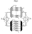
- FIG. 1 is a diagram for explaining a basic theory of an optical demultiplexing method and an optical multiplexing method according to the present invention.
- the explanation will be made, for example, on the assumption that a WDM light mixedly containing 10Gbi1/s signal lights and 40Gbit/s signal lights is once demultiplexed and then, again multiplexed.
- a WDM light S IN given from the left side of FIG. 1 is input to a port P 10 of an optical coupler 1.
- the input light is branched into two, and one branched light is output to a route R 1 on the upper side of the figure via a port P 11 , while the other branched light is output to a route R 2 on the lower side of the figure via a port P 12 .
- a 10Gbit/s demultiplexer 11, 1 x2 optical switches 12 1 to 12 21 and a 10Gbit/s multiplexer 13 are connected, and to the route R 2 side, a 40Gbit/s demultiplexer 21, 1 x2 optical switches 22 1 , 22 5 , 22 9 , 22 13 , 22 17 and 22 21 , and a 40Gbit/s multiplexer 23 are connected, so that output lights from the multiplexers 13 and 23 on the routes R 1 and R 2 are given respectively to ports P 21 and P 22 of an optical coupler 2 to be multiplexed, and a WDM light S OUT is output from a port 20.
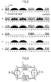
- FIG. 2 shows one example of a spectrum at each of points A to F in the configuration of FIG.1.
- the point A is an input end of the optical coupler 1
- the point B is an output end of the 10Gbit/s demultiplexer 11
- the point C is an output end of the 40Gbit/s demultiplexer 21
- the point D is an output end of the 10Gbit/s multiplexer 13
- the point E is an output end of the 40Gbit/s multiplexer 23
- the point F is an output end of the optical coupler 2.
- 10Gbit/s signal lights are arranged in wavelength grid numbers 1, 2, 12, 13, 14, 20 and 21, and 40Gbit/s signal lights are arranged in wavelength grid numbers 5, 9 and 17, on wavelength grids at 25GHz intervals.
- the 10Gbit/s signal lights it is possible to arrange the 10Gbit/s signal lights in all of the wavelength grid numbers in FIG. 2.
- the 40Gbit/s signal light has the spectral bandwidth four times the spectral bandwidth of the 10Gbit/s signal light, and therefore, needs to be arranged on the wavelength grids at 25GHz intervals while maintaining at least 100GHz intervals. Therefore, the wavelength grid numbers on which the 40Gbit/s signal lights can be arranged are, for example,1, 5, 9,13,17, 21 and the like, at 100GHz intervals.
- the WDM light S IN mixedly containing the signal lights of two modulating rates is branched for two routes R 1 and R 2 by the optical coupler 1, and thereafter, the branched lights are given to the 10Gbit/s demultiplexer 11 and the 40Gbit/s demultiplexer 21.
- output spectra of the 10Gbit/s demultiplexer 11 and the 40Gbit/s demultiplexer 21 each mixedly contains signal lights of two modulating rates, as shown in (B) and (C) of FIG. 2.
- the bold lines in (B) of FIG. 2 show transmission bands of 10Gbit/s demultiplexer 11 respectively corresponding to the wavelength grid numbers 1 to 21
- the bold lines in (C) of FIG. 2 show transmission bands of 40Gbit/s demultiplexer 21 respectively corresponding to the wavelength grid numbers 1, 5, 9,13,17 and 21.
- the 1 x2 optical switches 12 1 to 12 21 disposed to respective outputs of the 10Gbit/s demultiplexer 11 are set so that only channels in which the 10Gbit/s signal lights are arranged, are given to the latter staged 10Gbit/s multiplexer 13 but other channels are all blocked.
- the 1x2 optical switches 22 1 , 22 5 , 22 9 , 22 13 , 22 17 and 22 21 disposed to respective outputs of the 40Gbit/s demultiplexer 21 are set so that only channels in which the 40Gbit/s signal lights are arranged, are given to the latter staged 40Gbit/s multiplexer 23 but other channels are all blocked.
- optical paths of the respective 1 x2 optical switches corresponding to the wavelength grid numbers 1, 2, 12, 13, 14, 20 and 21 are set to the side of the route connected to the 10Gbit/s multiplexer 13, and optical paths of the respective 1 x2 optical switches corresponding to the other wavelength grid numbers 3 to 11 and 15 to 19 are set to the side of an optical terminator T.
- the optical paths of the respective 1 x2 optical switches corresponding to the wavelength grid numbers 5, 9 and 17 are set to the side of the route connected to the 40Gbit/s multiplexer 23, and the optical paths of the respective 1 x2 optical switches corresponding to the other wavelength grid numbers 1, 13 and 21 are set to the side of the optical terminator T.
- the optical terminator T is used for preventing Fresnel reflection.
- optical demultiplexing method and the optical multiplexing method according to the present invention as described in the above can also be realized, as shown in FIG. 3 for example, by respectively disposing, on the respective routes R 1 and R 2 , known optical devices 10 and 20, each utilizing a wavelength blocker, a wavelength selector switch or the like which is capable of selecting signal lights of arbitrary wavelengths among a plurality of signal lights contained in an input WDM light to output the selected signal lights as a WDM light.
- spectra at respective points A, D, E and F are the same as the spectra shown in (A), (D), (E) and (F) of FIG. 2.
- the known optical devices 10 and 20 it is possible to apply a configuration shown in FIG.
- optical device utilizing the wavelength selector switch it is possible to apply an optical system shown in FIG. 1 A of U. S. Patent No. 6,549,699 to realize a function equivalent to the plurality of 1 x2 optical switches shown in FIG. 1.
- the optical device used in the present invention is not limited to the above specific examples.
- optical demultiplexing method and the optical multiplexing method of the present invention as described in the above, it is possible to arrange the signal lights having different modulating rates at the arbitrary wavelengths. Further, since the optical demultiplexing method and the optical multiplexing method of the present invention can be realized using only the existing optical device as shown in the configuration examples of FIG. 1 and FIG. 3, economically excellent optical demultiplexing method and optical multiplexing method are realized.
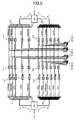
- FIG. 4 is a diagram showing an entire configuration of one embodiment of the optical transmission system according to the present invention.
- the present optical transmission system is such that, in a configuration same as that of a typical WDM optical transmission system shown in FIG. 13, a transmission terminal station 110 is configured by applying the optical multiplexing method of the present invention and also a reception terminal station 130 is configured by applying the optical demultiplexing method of the present invention, and further, an optical node apparatus 120 is configured by applying the optical demultiplexing method and the optical multiplexing method of the present invention.
- the transmission terminal station 110 includes, for example, a plurality of optical senders (OS) 111 generating 10Gbit/s signal lights corresponding to wavelength grids at 25GHz intervals and a multiplexer 113 multiplexing the respective 10Gbit/s signal lights. Further, the transmission terminal station 110 includes a plurality of optical senders (OS) 112 generating 40Gbit/s signal lights which are arranged on the wavelength grids at 25GHz intervals while maintaining 100GHz intervals, and a multiplexer 114 multiplexing the respective 40Gbit/s signal lights.
- OS optical senders
- the 10Gbit/s signal lights multiplexed by the multiplexer 113 and the 40Gbit/s signal lights multiplexed by the multiplexer 114 are multiplexed by an optical coupler 115, and thereafter, amplified by an optical post-amplifier 116 to be transmitted to an optical fiber transmission path L.
- the transmission terminal station 110 includes a management section 117 that manages information related to operational wavelengths and bit rates of the respective signal lights contained in a WDM light S to be transmitted to the optical fiber transmission path L When the wavelengths and bit rates of the signal lights are changed, this management section 117 sends a control signal to each of the optical senders 111 and 112 to control a driving condition of each of the optical senders 111 and 112, and changes over an on/off condition of the signal light output from each of the optical senders 111 and 112.
- the management section 117 has a function of generating a signal INF indicating the information related to the operational wavelengths and bit rates of the signal lights, to transmit the signal INF to the optical fiber transmission path L via a multiplexer 118 for transferring it to the downstream side.
- the optical node apparatus 120 once separates, for example, the WDM light S propagated through the optical fiber transmission path L into a 10Gbit/s signal light group and a 40Gbitls signal light group to perform the wavelength dispersion compensation for each signal light group, and thereafter, multiplexes the signal light groups to transmit the multiplexed light to the optical fiber transmission path L
- the input light from the optical fiber transmission path L is amplified up to a required level by an optical amplifier 121, and thereafter, the amplified light is given to an optical coupler 123 via a demultiplexer 122.
- the optical coupler 123 is equivalent to the optical coupler 1 in FIG. 1.
- the light sent to the route R 1 side passes through a 10GbH/s demultiplexer 211, a plurality of 1 x2 optical switches 212, a 10Gbit/s multiplexer 213 and a 10Gbit/s dispersion compensation fiber (DCF) 214 in this sequence to be given to an optical coupler 124, while the light sent to the route R 2 side passes through a 40Gbit/s demultiplexer 221, a plurality of 1 x2 optical switches 222, a 40Gbit/s multiplexer 223 and a 40Gbit/s dispersion compensation fiber (DCF) 224 in this sequence to be given to the optical coupler 124.
- DCF dispersion compensation fiber
- optical paths of the 1 x2 optical switches 212 and 222 on the routes R 1 and R 2 are changed over in accordance with control signals from a control section 125.
- the control section 125 takes out, from the demultiplexer 122, the signal INF indicating the information related to the operational wavelengths and bit rates of the signal lights; which is transmitted from the upstream side via the optical fiber transmission path L, and generates the control signals for determining connection conditions of the optical paths of the 1 x2 optical switches 212 and 222 in accordance with the information.
- the WDM light S which has been given to the optical coupler 124 and again multiplexed, is amplified up to a required level by an optical amplifier 126, and thereafter, is output to the optical fiber transmission path L.
- the reception terminal station 130 amplifies the WDM light S propagated through the optical fiber transmission path L up to a required level by an optical pre-amplifier 131, and thereafter, gives the amplified light to an optical coupler 133 via a demultiplexer 132, to send two branched lights respectively to the routes R 1 and R 2 .
- the light sent to the route R 1 side is demultiplexed by a 10Gbit/s demultiplexer 311, and thereafter, the demultiplexed lights are received by 10Gbit/s optical receivers (OR) 134 via 1 x2 optical switches 312 corresponding to the respective demultiplexed lights.
- the light sent to the route R 2 side is demultiplexed by a 40Gbit/s demultiplexer 321, and thereafter, the demultiplexed lights are received by 40Gbit/s optical receivers (OR) 135 via 1 x2 optical switches 322 corresponding to the respective demultiplexed lights.
- Optical paths of the 1 x2 optical switches 312 and 322 on the routes R 1 and R 2 are changed over in accordance with control signals from a control section 136.
- the control section 136 takes out from the demultiplexer 132, the signal INF indicating the information related to the operational wavelengths and bit rates of the signal lights, which is transmitted from the upstream side via the optical fiber transmission path L, and generates the control signals for determining connection conditions of the optical paths of the 1 x2 optical switches 312 and 322 in accordance with the information.
- the information related to the operational wavelengths and bit rates of the signal lights in the transmission terminal station 110 is transmitted to the optical node apparatus 120 on the optical fiber transmission path L and also to the reception terminal station 130, and the 1x2 optical switches in the optical node apparatus 120 and the reception terminal station 130 are controlled in accordance with the information.
- the WDM light S in which the 10Gbit/s signal lights and the 40Gbit/s signal lights are arranged at arbitrary wavelengths on the wavelength grids at 25GHz intervals, to the reception terminal station 130 from the transmission terminal station 110, while maintaining excellent signal qualities.
- wavelength dispersion compensation for each of the 10Gbit/s signal light group and the 40Gbit/s signal light group in the optical node apparatus 120. Therefore, even if optimum values of wavelength dispersion compensation amount are different from each other depending on the bit rates of the signal lights, an optimum wavelength dispersion compensation amount can be given to each of the 10Gbit/s signal lights and the 40Gbit/s signal lights.
- the add/drop multiplexing on the signal lights of particular wavelengths is made possible, by further disposing 1 x2 optical switches 214 and 224 and 2x1 optical switches 215 and 225 , on the latter stage of the 1x2 optical switches 212 and 222 which control the transmission (through) and the block (off) of the signal lights on the routes R 1 and R 2 .
- each of the optical switches 212, 222, 214, 224, 215 and 225 is controlled by the control section in accordance with the information related to the operational wavelengths and bit rates transmitted from the transmission terminal station 110.
- the setting example of optical paths of the respective optical switches shown in the solid lines corresponds to the case where the 10Gbit/s signal light of the wavelength block number 13 and the 40Gbit/s signal lights of the wavelength block numbers 5 and 17 are subjected to the add/drop multiplexing at corresponding nodes, but the other signal lights are passed through corresponding nodes. Note, it is possible to appropriately determine whether or not optical senders (OS) and optical receivers (OR) are prepared for the wavelengths of the signal lights which are not subjected to the add/drop multiplexing at the corresponding nodes.
- OS optical senders
- OR optical receivers
- the optical node apparatus 120 separates the WDM light to the 10Gbit/s signal light group and the 40Gbit/s signal light group.
- the configuration may be such that the WDM light is separated to each signal light group using the configuration in which the optical device utilizing the wavelength blocker, the wavelength selector switch or the like, as shown in FIG. 3, is disposed on each of the routes R 1 and R 2 .
- the configuration may be such that the optical sender for the wavelength which is not used is removed and instead, an optical terminator is connected. In such a case, in order to cope with changes in the wavelengths and bit rates of the signal lights, the replacement of the optical sender with the optical terminator or the like are performed.
- the configuration may be such that the optical receiver for the wavelength which is not used is removed and instead, an optical terminator is connected.
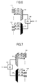
- FIG. 9 is a diagram showing a main part configuration of the optical node apparatus according to the application example.
- the present optical node apparatus is characterized in that a branching ratio between ports P 11 and P 12 of an optical coupler 123' which branches an input light into two, can be set at an arbitrary ratio a:b which is not necessarily 1:1, so that the power of the signal light input to each of the dispersion compensation fibers 214 and 224 can be set at a different value for each bit rate. Further, similarly to this, a branching ratio between ports P 21 and P 22 of an output side optical coupler 124' which multiplexes the output lights from the respective dispersion compensation fibers 214 and 224, can be set at an arbitrary ratio c:d.
- an upper limit value of the signal light power which may be input to a dispersion compensation fiber, is often different depending on a bit rate of a signal light, in terms of the system design. This is because it is necessary to lower the signal light power to suppress the signal light phase modulation generated in the dispersion compensation fiber as much as possible, since the signal light is easy to be influenced by the wavelength dispersion, the higher the bit rate is. Therefore, by designing in optimum the branching ratio a:b of the input side optical coupler 123' according to the upper limit value of the signal light power corresponding to each bit rate of the routes R 1 and R 2 , it becomes possible to suppress the generation of the signal light phase modulation in each of the dispersion compensation fibers 214 and 224.
- the branching ratio of the input side optical coupler 123' is designed so that the power of the WDM light output to the optical fiber transmission path L is optimized, to prevent the deterioration of the transmission characteristic.
- the branching ratio of the optical coupler 123' is set at the arbitrary ratio which is not necessarily 1:1 so that the optimization of the signal light power at each bit rate is achieved.
- the configuration may be such that the branching ratio of the optical coupler is set at 1:1 for example, so that the power of each signal light after branched is optimized using a loss medium or an amplification medium.
- the optimum designing of the branching ratio of the optical coupler is advantageous in terms of the less deterioration in an S/N ratio of the signal light.
- the application example of the optical node apparatus as described in the above is surely effective for the configuration shown in FIG. 3 applied with the optical devices 10 and 20 each utilizing the wavelength blocker, the wavelength selector switch or the like.
- a configuration example in such a case is shown in FIG. 10.
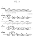
- the 40Gbit/s signal lights need to be maintained at 100GHz intervals or more considering the spectral expansion thereof. Therefore, the wavelengths at which the 40Gbit/s signal lights can be arranged are restricted to the wavelength grid numbers 1, 5, 9, 13, 17, 21 and the like, for example.
- the description will be made on an application example in which the 40Gbit/s signal lights can also be arranged at arbitrary wavelengths on the wavelength grids at 25GHz intervals.
- FIG. 11 is a diagram showing a main part configuration of an optical node apparatus according to the application example.
- the present optical node apparatus branches an input light to five routes R 1 to R 5 by an optical coupler 123", to allocate one route R 1 as a route for the 10Gbit/s signal lights and four routes R 2 to R 5 as routes for the 40Gbit/s signal lights, and again multiplexes signal lights which have passed through the respective routes R 1 to R 5 to be subjected to the wavelength dispersion compensation for each bit rate, by an optical coupler 124".
- demultiplexer 211 arranged on the route R 1 , the plurality of 1x2 optical switches 212, the multiplexer 213 and the dispersion compensation fiber 214, each for the 10Gbit/s signal lights, are the same as those in the above embodiment.
- demultiplexers 221 1 to 221 4 and multiplexers 223 1 to 223 4 respectively arranged on the routes R 2 to R 5 for the 40Gbit/s signal lights are previously set so that the center wavelengths (frequencies) in transmission bands thereof are shifted to each other by 25GHz, and the demultiplexer and the multiplexer whose transmission bands are coincident with each other are connected via a plurality of 1x2 optical switches.
- dispersion compensation fibers 224 1 to 224 4 on the routes R 2 to R 4 there are used common dispersion compensation fibers whose wavelength dispersion compensation amounts for the 40Gbit/s signal lights are optimized.
- the demultiplexer and the multiplexer each having the transmission band whose center wavelength is coincident with the wavelength of the 40Gbit/s signal light. Therefore, by changing over optical paths of 1 x2 optical switches 222 1 to 222 4 on the routes R 2 to R 5 corresponding to the wavelength allocation of the 40Gbit/s signal lights, the multiplexing/demuniplexing of the 40Gbit/s signal lights can be performed.
- the application example of the optical node apparatus which performs the wavelength dispersion compensation has been shown here.
- the present invention to an optical node apparatus which performs the add/drop multiplexing on the signal lights.
- one example has been shown in which the 10Gbit/s signal lights and the 40Gbit/s signal lights mixedly exist on the wavelength grids at 25GHz intervals.
- the intervals of the wavelength grids and the modulating rates of the signal lights are not limited thereto.
Landscapes
- Engineering & Computer Science (AREA)
- Computer Networks & Wireless Communication (AREA)
- Signal Processing (AREA)
- Optical Communication System (AREA)
Applications Claiming Priority (1)
| Application Number | Priority Date | Filing Date | Title |
|---|---|---|---|
| JP2004270862A JP4152932B2 (ja) | 2004-09-17 | 2004-09-17 | 光分波方法および光合波方法、並びに、それを用いた光伝送装置 |
Publications (2)
| Publication Number | Publication Date |
|---|---|
| EP1638232A2 true EP1638232A2 (fr) | 2006-03-22 |
| EP1638232A3 EP1638232A3 (fr) | 2015-03-11 |
Family
ID=35466440
Family Applications (1)
| Application Number | Title | Priority Date | Filing Date |
|---|---|---|---|
| EP04030293.7A Withdrawn EP1638232A3 (fr) | 2004-09-17 | 2004-12-21 | Méthode de démultiplexage et multiplexage optique et appareil de transmission optique l'utilisant |
Country Status (3)
| Country | Link |
|---|---|
| US (1) | US7519296B2 (fr) |
| EP (1) | EP1638232A3 (fr) |
| JP (1) | JP4152932B2 (fr) |
Cited By (1)
| Publication number | Priority date | Publication date | Assignee | Title |
|---|---|---|---|---|
| FR2903543A1 (fr) * | 2006-07-06 | 2008-01-11 | Alcatel Sa | Dispositif reconfigurable de multiplexage optique a insertion/extraction comportant des modules d'insertion/extraction securises de type wss |
Families Citing this family (17)
| Publication number | Priority date | Publication date | Assignee | Title |
|---|---|---|---|---|
| ATE364269T1 (de) * | 2005-03-07 | 2007-06-15 | Alcatel Lucent | Wellenlängenraster für dwdm |
| DE102006008404B4 (de) * | 2006-02-21 | 2011-04-14 | Adva Ag Optical Networking | Optische Schaltungsstrukturen zur Realisierung eines Knotens höherer Ordnung in einem optischen Übertragungsnetzwerk sowie Basis- und Erweiterungsschaltungsstruktur |
| JP4827672B2 (ja) * | 2006-09-21 | 2011-11-30 | 富士通株式会社 | Wdm光伝送システムおよびwdm光伝送方法 |
| JP4796183B2 (ja) * | 2007-03-16 | 2011-10-19 | 富士通株式会社 | 光伝送装置 |
| JP4850288B2 (ja) * | 2007-08-27 | 2012-01-11 | 富士通株式会社 | ネットワーク管理システム、中継装置及び方法 |
| JP5593587B2 (ja) * | 2008-03-05 | 2014-09-24 | 日本電気株式会社 | 波長多重分離方式及び波長多重分離方法 |
| JP2010074565A (ja) * | 2008-09-18 | 2010-04-02 | Nippon Telegr & Teleph Corp <Ntt> | 光分岐挿入多重化装置 |
| JP2010226169A (ja) * | 2009-03-19 | 2010-10-07 | Fujitsu Ltd | 光送信装置、光通信方法および光通信システム |
| JP5617503B2 (ja) | 2010-09-30 | 2014-11-05 | 富士通株式会社 | 光ネットワーク中継装置 |
| JP5807338B2 (ja) | 2011-02-14 | 2015-11-10 | 富士通株式会社 | 光伝送装置および光フィルタ回路 |
| JP5312553B2 (ja) * | 2011-10-28 | 2013-10-09 | 日本電信電話株式会社 | 光分岐挿入多重化装置 |
| US8693873B2 (en) * | 2011-12-02 | 2014-04-08 | At&T Intellectual Property I, L.P. | Apparatus and method for improved distributed compensation of filtering effects mitigation in an optical network |
| JP5775012B2 (ja) * | 2012-03-02 | 2015-09-09 | 日本電信電話株式会社 | 光識別再生装置及び光経路切り替え装置 |
| JP5991210B2 (ja) * | 2012-03-29 | 2016-09-14 | 富士通株式会社 | 光信号送信装置 |
| CN104685804B (zh) * | 2012-09-27 | 2017-06-09 | 日本电气株式会社 | 光分路/耦合设备和光分路/耦合方法 |
| JP6223931B2 (ja) * | 2014-09-02 | 2017-11-01 | 日本電信電話株式会社 | 光増幅装置 |
| WO2018179686A1 (fr) * | 2017-03-31 | 2018-10-04 | 日本電気株式会社 | Dispositif de démultiplexage de signal optique, dispositif de réception de signal optique, dispositif d'émission/réception de signal optique et procédé de démultiplexage de signal optique |
Family Cites Families (13)
| Publication number | Priority date | Publication date | Assignee | Title |
|---|---|---|---|---|
| JP3233204B2 (ja) | 1997-08-05 | 2001-11-26 | 日本電気株式会社 | 波長光adm装置 |
| US6404525B1 (en) * | 1997-07-31 | 2002-06-11 | Nec Corporation | Optical add-drop multiplexer |
| US6310690B1 (en) * | 1999-02-10 | 2001-10-30 | Avanex Corporation | Dense wavelength division multiplexer utilizing an asymmetric pass band interferometer |
| JP3772594B2 (ja) | 1999-07-15 | 2006-05-10 | 富士通株式会社 | 光ネットワーク中継装置 |
| KR20010061613A (ko) * | 1999-12-28 | 2001-07-07 | 윤종용 | 업그레이드 가능한 파장 분할 다중화 시스템의 노드 구조 |
| CA2337598A1 (fr) | 2000-03-31 | 2001-09-30 | Magaly Spector | Appareil pour le demultiplexage/multiplexage de signaux optiques modules a differents debits binaires dans des systemes mrl |
| US6445850B1 (en) * | 2000-08-11 | 2002-09-03 | Sycamore Networks, Inc. | Method and apparatus for per-band compensation with gap-free band structure for high speed DWDM transmission |
| JP4647074B2 (ja) * | 2000-10-04 | 2011-03-09 | 富士通株式会社 | 波長多重光通信システム |
| FR2821504B1 (fr) * | 2001-02-23 | 2005-12-09 | Cit Alcatel | Dispositif d'extraction de frequence |
| US6504970B2 (en) | 2001-03-15 | 2003-01-07 | Lucent Technologies Inc. | Planar lightwave wavelength blocker |
| US6549699B2 (en) * | 2001-03-19 | 2003-04-15 | Capella Photonics, Inc. | Reconfigurable all-optical multiplexers with simultaneous add-drop capability |
| JP4161808B2 (ja) | 2002-08-21 | 2008-10-08 | 住友電気工業株式会社 | 光伝送システム |
| JP4020809B2 (ja) | 2003-03-26 | 2007-12-12 | 富士通株式会社 | 波長分割多重伝送システム |
-
2004
- 2004-09-17 JP JP2004270862A patent/JP4152932B2/ja not_active Expired - Fee Related
- 2004-12-21 EP EP04030293.7A patent/EP1638232A3/fr not_active Withdrawn
- 2004-12-22 US US11/017,941 patent/US7519296B2/en not_active Expired - Lifetime
Non-Patent Citations (1)
| Title |
|---|
| None * |
Cited By (2)
| Publication number | Priority date | Publication date | Assignee | Title |
|---|---|---|---|---|
| FR2903543A1 (fr) * | 2006-07-06 | 2008-01-11 | Alcatel Sa | Dispositif reconfigurable de multiplexage optique a insertion/extraction comportant des modules d'insertion/extraction securises de type wss |
| EP1876743A3 (fr) * | 2006-07-06 | 2008-12-24 | Alcatel Lucent | Dispositif reconfigurable de multiplexage optique à insertion/extraction comportant des modules d'insertion/extraction sécurisés de type WSS |
Also Published As
| Publication number | Publication date |
|---|---|
| JP4152932B2 (ja) | 2008-09-17 |
| US20060062577A1 (en) | 2006-03-23 |
| EP1638232A3 (fr) | 2015-03-11 |
| JP2006086920A (ja) | 2006-03-30 |
| US7519296B2 (en) | 2009-04-14 |
Similar Documents
| Publication | Publication Date | Title |
|---|---|---|
| US7437074B2 (en) | Wavelength division multiplexing transmission system | |
| US10200145B2 (en) | Flexible grid optical spectrum transmitter, receiver, and transceiver | |
| US7519296B2 (en) | Optical demultiplexing method and optical multiplexing method, and optical transmission apparatus using same | |
| US8958695B2 (en) | Optical adding and dropping device and optical transmission apparatus | |
| CN1713558B (zh) | 光学装置及传送光信号的方法 | |
| US8965220B2 (en) | Reconfigurable optical add/drop multiplexer and procedure for outputting optical signals from such multiplexer | |
| JP4252219B2 (ja) | 光ノード装置及び該装置を備えたシステム | |
| EP1126648A2 (fr) | Equipement, transpondeur et méthodes sur fibre optique | |
| EP1503532B1 (fr) | Réseau optique avec rejet de bandes partielles et dérivation | |
| GB2352104A (en) | Upgrading from a single wavelength to a multi-wavelength optical communications system | |
| US7483637B2 (en) | Optical ring network with optical subnets and method | |
| US6512864B1 (en) | Optical multiplexer/demultiplexer arrangement for WDM signals having in-band and out-of-band signal components | |
| US20050286896A1 (en) | Hybrid optical ring network | |
| JP2012169870A (ja) | 光伝送装置および光フィルタ回路 | |
| US7181095B1 (en) | Low loss, noise filtering multiplexer/demultiplexer for reconfigurable OADMs | |
| EP1109341A2 (fr) | Multiplexeur d'insertion/extraction de longueur d'onde optique pour débits de transmission à signaux duaux | |
| CN110546901B (zh) | 光信号解复用设备、光信号接收设备、光信号发送/接收设备以及光信号解复用方法 | |
| US10659165B2 (en) | Optical transmission device | |
| EP1009120A2 (fr) | Dispositif d'insertion/extraction optique pour canaux multiples, multiplexeur et démultiplexeur | |
| EP1608098A1 (fr) | Multipléxeur optique à insertion-extraction avec une configuration de canal alternée | |
| CN104160645A (zh) | 利用融合信号添加和移除的多频带可重配置光学分插复用 | |
| Collings et al. | Optical node architectures | |
| US20120183292A1 (en) | Method and apparatus for trafficking wavelengths of different spacings within an optical node | |
| EP3588808B1 (fr) | Twdm pon à rapport de division variable | |
| JP3784998B2 (ja) | 光伝送装置およびリングネットワーク |
Legal Events
| Date | Code | Title | Description |
|---|---|---|---|
| PUAI | Public reference made under article 153(3) epc to a published international application that has entered the european phase |
Free format text: ORIGINAL CODE: 0009012 |
|
| AK | Designated contracting states |
Kind code of ref document: A2 Designated state(s): AT BE BG CH CY CZ DE DK EE ES FI FR GB GR HU IE IS IT LI LT LU MC NL PL PT RO SE SI SK TR |
|
| AX | Request for extension of the european patent |
Extension state: AL BA HR LV MK YU |
|
| PUAL | Search report despatched |
Free format text: ORIGINAL CODE: 0009013 |
|
| AK | Designated contracting states |
Kind code of ref document: A3 Designated state(s): AT BE BG CH CY CZ DE DK EE ES FI FR GB GR HU IE IS IT LI LT LU MC NL PL PT RO SE SI SK TR |
|
| AX | Request for extension of the european patent |
Extension state: AL BA HR LV MK YU |
|
| RIC1 | Information provided on ipc code assigned before grant |
Ipc: H04Q 11/00 20060101ALI20150202BHEP Ipc: H04J 14/02 20060101AFI20150202BHEP |
|
| 17P | Request for examination filed |
Effective date: 20150602 |
|
| RBV | Designated contracting states (corrected) |
Designated state(s): AT BE BG CH CY CZ DE DK EE ES FI FR GB GR HU IE IS IT LI LT LU MC NL PL PT RO SE SI SK TR |
|
| AKX | Designation fees paid |
Designated state(s): DE FR GB |
|
| AXX | Extension fees paid |
Extension state: AL Extension state: YU Extension state: MK Extension state: LV Extension state: BA Extension state: HR |
|
| 17Q | First examination report despatched |
Effective date: 20171030 |
|
| STAA | Information on the status of an ep patent application or granted ep patent |
Free format text: STATUS: THE APPLICATION HAS BEEN WITHDRAWN |
|
| 18W | Application withdrawn |
Effective date: 20171218 |