EP1639229B1 - Vorrichtung und verfahren zur abdichtung eines bohrloches - Google Patents
Vorrichtung und verfahren zur abdichtung eines bohrloches Download PDFInfo
- Publication number
- EP1639229B1 EP1639229B1 EP04743112A EP04743112A EP1639229B1 EP 1639229 B1 EP1639229 B1 EP 1639229B1 EP 04743112 A EP04743112 A EP 04743112A EP 04743112 A EP04743112 A EP 04743112A EP 1639229 B1 EP1639229 B1 EP 1639229B1
- Authority
- EP
- European Patent Office
- Prior art keywords
- patch
- tubular
- wellbore
- expander
- open hole
- Prior art date
- Legal status (The legal status is an assumption and is not a legal conclusion. Google has not performed a legal analysis and makes no representation as to the accuracy of the status listed.)
- Expired - Lifetime
Links
- 238000007789 sealing Methods 0.000 title claims abstract description 46
- 238000000034 method Methods 0.000 title claims abstract description 33
- 239000002184 metal Substances 0.000 claims description 61
- 239000012530 fluid Substances 0.000 claims description 23
- 238000004519 manufacturing process Methods 0.000 claims description 13
- 238000006073 displacement reaction Methods 0.000 claims description 6
- 230000015572 biosynthetic process Effects 0.000 description 8
- 238000005755 formation reaction Methods 0.000 description 8
- 239000004215 Carbon black (E152) Substances 0.000 description 7
- 239000013536 elastomeric material Substances 0.000 description 7
- 229930195733 hydrocarbon Natural products 0.000 description 7
- 150000002430 hydrocarbons Chemical group 0.000 description 7
- 229910000831 Steel Inorganic materials 0.000 description 6
- 239000010959 steel Substances 0.000 description 6
- 239000004568 cement Substances 0.000 description 4
- 239000000463 material Substances 0.000 description 4
- XLYOFNOQVPJJNP-UHFFFAOYSA-N water Substances O XLYOFNOQVPJJNP-UHFFFAOYSA-N 0.000 description 4
- 230000003247 decreasing effect Effects 0.000 description 3
- 239000012858 resilient material Substances 0.000 description 3
- 229920002943 EPDM rubber Polymers 0.000 description 2
- 230000000295 complement effect Effects 0.000 description 2
- 238000005260 corrosion Methods 0.000 description 2
- 230000007797 corrosion Effects 0.000 description 2
- 230000007423 decrease Effects 0.000 description 2
- 239000004033 plastic Substances 0.000 description 2
- -1 preferably Substances 0.000 description 2
- 238000002407 reforming Methods 0.000 description 2
- 229910000975 Carbon steel Inorganic materials 0.000 description 1
- 229910001209 Low-carbon steel Inorganic materials 0.000 description 1
- 229920006169 Perfluoroelastomer Polymers 0.000 description 1
- 239000004734 Polyphenylene sulfide Substances 0.000 description 1
- 238000004873 anchoring Methods 0.000 description 1
- 239000010962 carbon steel Substances 0.000 description 1
- 239000011248 coating agent Substances 0.000 description 1
- 238000000576 coating method Methods 0.000 description 1
- 239000004020 conductor Substances 0.000 description 1
- 230000001419 dependent effect Effects 0.000 description 1
- 229920001971 elastomer Polymers 0.000 description 1
- 230000008676 import Effects 0.000 description 1
- 238000009434 installation Methods 0.000 description 1
- 238000002955 isolation Methods 0.000 description 1
- 229910001092 metal group alloy Inorganic materials 0.000 description 1
- 238000012544 monitoring process Methods 0.000 description 1
- 229920000642 polymer Polymers 0.000 description 1
- 229920000069 polyphenylene sulfide Polymers 0.000 description 1
- 229920001343 polytetrafluoroethylene Polymers 0.000 description 1
- 239000004810 polytetrafluoroethylene Substances 0.000 description 1
- 230000001681 protective effect Effects 0.000 description 1
- 229920002379 silicone rubber Polymers 0.000 description 1
- 239000004945 silicone rubber Substances 0.000 description 1
- 239000002002 slurry Substances 0.000 description 1
Images



Classifications
-
- E—FIXED CONSTRUCTIONS
- E21—EARTH OR ROCK DRILLING; MINING
- E21B—EARTH OR ROCK DRILLING; OBTAINING OIL, GAS, WATER, SOLUBLE OR MELTABLE MATERIALS OR A SLURRY OF MINERALS FROM WELLS
- E21B41/00—Equipment or details not covered by groups E21B15/00 - E21B40/00
- E21B41/0035—Apparatus or methods for multilateral well technology, e.g. for the completion of or workover on wells with one or more lateral branches
- E21B41/0042—Apparatus or methods for multilateral well technology, e.g. for the completion of or workover on wells with one or more lateral branches characterised by sealing the junction between a lateral and a main bore
-
- E—FIXED CONSTRUCTIONS
- E21—EARTH OR ROCK DRILLING; MINING
- E21B—EARTH OR ROCK DRILLING; OBTAINING OIL, GAS, WATER, SOLUBLE OR MELTABLE MATERIALS OR A SLURRY OF MINERALS FROM WELLS
- E21B29/00—Cutting or destroying pipes, packers, plugs or wire lines, located in boreholes or wells, e.g. cutting of damaged pipes, of windows; Deforming of pipes in boreholes or wells; Reconditioning of well casings while in the ground
- E21B29/10—Reconditioning of well casings, e.g. straightening
-
- E—FIXED CONSTRUCTIONS
- E21—EARTH OR ROCK DRILLING; MINING
- E21B—EARTH OR ROCK DRILLING; OBTAINING OIL, GAS, WATER, SOLUBLE OR MELTABLE MATERIALS OR A SLURRY OF MINERALS FROM WELLS
- E21B43/00—Methods or apparatus for obtaining oil, gas, water, soluble or meltable materials or a slurry of minerals from wells
- E21B43/02—Subsoil filtering
- E21B43/10—Setting of casings, screens, liners or the like in wells
- E21B43/103—Setting of casings, screens, liners or the like in wells of expandable casings, screens, liners, or the like
- E21B43/105—Expanding tools specially adapted therefor
Definitions
- the present invention relates to an apparatus and method for forming an annular seal between a patch and a tubular in a wellbore or between a patch and an open hole wellbore.
- a patch may also be used to seal holes in the casing caused by corrosion or to reinforce corroded casing sections which have not yet become perforated. Still other applications, such as bridging the gap between sections of parted casing will also be apparent to those skilled in the art.
- the wellbore is uncased, and an open face is established across the hydrocarbon bearing zone.
- a patch may also be used in such open face wellbores in order to increase the mechanical strength of the wellbore wall or to seal off an open face zone, for example, a water-producing zone. Where the patch is used to increase the mechanical strength of the wellbore wall, the patch is subsequently perforated where it traverses a hydrocarbon bearing zone of the formation.
- a sandscreen is used in open face wellbores.
- the sandscreen that is run into the open face wellbore comprises one or more tubular ("patch") sections that lie across one or more non-hydrocarbon-bearing intervals of the wellbore, for example, a water-producing interval, and one or more screen sections that lie across one or more hydrocarbon-bearing intervals of the wellbore.
- an external casing packer is set in the annulus formed between the tubular section(s) of the sandscreen and the open face wellbore at each end of the tubular section(s).
- a cement slurry may also be introduced into the annulus formed between the tubular section(s) and the open face wellbore to ensure that the non-hydrocarbon-bearing interval(s), for example, water producing interval(s) is effectively sealed off. It would therefore be advantageous to eliminate the requirement for the external casing packers and for cementing the tubular section(s) of a sandscreen.
- the radial thickness of the wall of the cylindrical steel sleeve decreases.
- the maximum expansion ratio for a tubular metal patch is about 30%. A problem therefore arises when the minimum restriction in the production tubing is small compared with the diameter of the wellbore as it may not be possible to expand the patch to form a fluid-tight seal with the casing or the wall of an open hole wellbore without exceeding the maximum expansion ratio.
- a solution to this problem has been to use a vertically corrugated metal liner (for example, as described in US 3,203,451 ) wherein the external cross-sectional perimeter of the corrugated liner is greater than the internal cross-sectional circumference of the casing but the maximum external cross-sectional dimension of the corrugated liner is less than the internal diameter of the casing so the liner can be inserted into the casing.
- an expander tool is run through the corrugated liner to cause it to assume a cylindrical shape inside the casing. The liner is thus left in substantially maximum compressive hoop stress.
- An expansion tool comprising an expanding cone, a collet head and collet spring arms is described.
- the arms have outwardly enlarged portions which perform the final forming action to force the corrugated liner into a substantially cylindrical shape as the cone and collet head are pulled through the corrugated tube. It is said that the expression "expanding" the liner into contact with the casing may be misleading.
- the expanding cone does expand the liner in the sense that it forces the outer ridges of the corrugations outwardly until they come in contact with the casing.
- the inner corrugations are, in a sense, expanded radially outwardly until they come in contact with the casing. It would therefore be evident to the person skilled in the art that the reformed liner is merely elastically reformed and is not subsequently plastically expanded to form a seal with the wellbore wall.
- the apparatus comprises a body having a top portion, a bottom portion and a middle portion, the middle portion having an outer diameter greater than the top portion and an outer diameter greater than the bottom portion; a first set of fingers disposed around the top portion of said body and a second set of fingers disposed around the bottom portion of said body; the arrangement being such that, in use, said fingers can be urged radially outwardly by displacement thereof over said middle portion (collet expander).
- a cone is located above said body to facilitate deformation of the liner patch.
- the liner patch is expanded over the cone and finally over the fingers as the apparatus is pulled all of the way through the liner patch.
- expansion refers to elastically reforming the patch as opposed to plastically expanding the reformed patch.
- US Patent Application US 2002/018527 relates to methods and apparatus for expanding tubulars in a wellbore.
- An embodiment of the apparatus comprises an electric motor, at least one pump and a hydraulic fluid reservoir disposed in a housing with an expansion tool disposed therebelow.
- the apparatus is run into the well on a wireline which provides support for the weight of the apparatus and electrical power for the components therein.
- the apparatus is lowered into a tubular in a wellbore to a predetermined depth. Thereafter, electric power supplied to the motor operates the pump to provide pressurised fluid to actuate the expansion tool and the shaft extending from the pump provides rotational power to the expansion tool.
- the apparatus can have a tractor run into the well on the wireline along with the expansion tool and housing.
- the tractor imports axial movement to the apparatus in the wellbore while the expansion tool rotates and expandable members thereupon increase the diameter of the tubular.
- the apparatus can be equipped with an anchor assembly to prevent rotational movement of the housing while allowing the apparatus to move axially within the wellbore.
- the methods disclosed in US 2002/018527 require the tubular to be installed into the desired location within the wellbore prior to the apparatus being lowered into the wellbore to expand the tubular.
- the patch Once at the desired location in the wellbore, the patch may be elastically reformed into a substantially regular tubular shape having an outer diameter greater than the minimum restriction in the wellbore and subsequently at least a portion of the reformed tubular patch may be plastically expanded to form a fluid tight seal with the wall of the wellbore (open face wellbore, or a cased/lined wellbore) wherein the expansion ratio for the reformed patch is in the range 10 to 30%.
- an apparatus for plastically expanding a tubular patch in a wellbore comprising:
- a method for sealing a hole in a tubular in a wellbore or for sealing an open hole interval (also referred to as an "open face interval") of a wellbore comprising:
- the apparatus for plastically expanding the tubular patch may be run into the wellbore suspended from conventional wireline (a reinforced steel cable encasing one or more electrical wires or segmented electrical conductors) which provides support for the weight of the apparatus and electrical power for actuating the components of the expansion tool.
- wireline a reinforced steel cable encasing one or more electrical wires or segmented electrical conductors
- the apparatus may be run into the wellbore suspended from electric coiled tubing. Suitable electric coiled tubing is described in UK patent application no. GB 2359571-A .
- the apparatus may comprise a single electric motor for providing motive power to the mechanical means for radially extending the gripping member(s) of the gripping assembly, for providing motive power to the mechanical means for radially extending the plurality of expander elements of the expander tool and for rotating the expander tool, typically via a drive means.
- the mechanical means for radially extending the gripping member(s), the mechanical means for radially extending the plurality of expander elements and the drive means for rotating the expander tool may be provided with dedicated electric motors.
- the mechanical means for radially extending the gripping member(s) of the gripping assembly and the mechanical means for radially extending the expander elements of the expander tool are also capable of radially retracting the gripping member(s) and expander elements respectively.
- the mechanical means for radially extending and retracting the expander elements of the expander tool is a jack mechanism or a cone displacement mechanism comprising a conical member that is moveable in a longitudinal direction with respect to the expander elements such that the expander elements are displaced radially outwardly or inwardly over the tapering surface of the conical member.
- Any other suitable electrically actuated mechanical means known to the person skilled in the art for radially extending and retracting the expander elements may also be employed.
- the drive means for rotating the expander tool is a rotatable shaft.
- the electric motor provides rotational movement to an output shaft that is connected to the expander tool to provide rotation thereto.
- the expander tool may be hydraulically actuated via at least one hydraulic pump.
- electric power supplied to the motor may be used to operate the pump to provide pressurised fluid to the expander tool to radially extend the expander elements.
- the pressurised fluid may be used to actuate the cone displacement mechanism.
- the pressurised fluid may be used to directly urge the expander elements radially outwards into engagement with the interior wall of the patch.
- a shaft extending from the hydraulic pump may provide rotational motion to the expansion tool.
- the apparatus of the present invention may comprise a reservoir for a hydraulic fluid disposed in a housing.
- the expansion tool is arranged below the housing.
- the pressurised fluid may be filtered wellbore fluid.
- the interior wall of the tubular patch preferably, a tubular metal patch
- the at least one radially extendible gripping member of the gripping assembly is gripped by the least one radially extendible gripping member of the gripping assembly, for example, by at least one radially extendible "slip".
- the at least one radially extendible gripping member grips the interior wall of the tubular metal patch at the upper end thereof.
- the gripping member(s) comprises teeth or other gripping elements.
- the apparatus is provided with a plurality of "slips", preferably 2 to 4 slips. Suitable "slips" for use with the patch would be well known to the person skilled in the art.
- the mechanical means for radially extending and retracting the gripping member(s) of the gripping assembly may be a jack mechanism or a cone displacement mechanism, as described above for the expander tool.
- the gripping assembly remains fixed in place in the tubular patch while the expander tool is rotated i.e. the gripping assembly does not rotate with the expander tool.
- the radially extendible gripping member(s) of the gripping assembly may be hydraulically actuated, as described above for the expander tool.
- the electric motor may drive a hydraulic pump thereby providing pressurised fluid to the gripping assembly to radially extend the gripping member(s)
- an upper section of the patch may be fixed in position in the wellbore by means of a plurality of mechanical dimples, for example circular shaped dimples arranged circumferentially around the tubing at the desired location, as described in Figure 16 of US 6,223,823 .
- a plurality of mechanical dimples for example circular shaped dimples arranged circumferentially around the tubing at the desired location, as described in Figure 16 of US 6,223,823 .
- at least 3 dimples are provided.
- the mechanical dimples may be activated by means of internal pressure applied by the expander elements of the expander tool.
- a resilient annular sealing member is provided on the external surface of the patch in the vicinity of the dimples to impart an anchoring surface against which the dimples engage thus improving the contact between the patch and the wall of the tubular (for example, the casing or liner of a wellbore) or with the open hole wellbore (open face wellbore).
- the gripping assembly may be omitted from the apparatus of the present invention.
- the tubular patch system has been lowered to a level proximate a perforation or a damaged section of a tubular (for example, casing or liner) or the system lies within an open hole interval of the wellbore, at least a portion of the tubular patch is plastically expanded by rotating the expander tool and actuating the mechanical means for radially extending the expander elements such the expander elements engage with the interior wall of the patch and a portion of the patch is plastically expanded against the wall of the tubular (for example, casing or liner) or the wall of the open hole wellbore thereby forming an annular fluid-tight seal.
- the expander elements of the expander tool are rollers or balls that may be radially extended or retracted via the electrically actuated mechanical means (for example, a jack mechanism or cone displacement mechanism).
- the rollers have a longitudinal length of from 0.5 to 5 inches (1.3 to 12.7 cm), for example 0.5 to 3 (1.3 to 7.6 cm) inches with the longitudinal length of the annular seal corresponding to the longitudinal length of the rollers.
- the radially extendible elements of the expander tool are balls
- the annular seal has a longitudinal length of approximately half the ball diameter. The diameter of the balls and hence the longitudinal length of the annular seal is dependent upon the internal diameter of the wellbore and the external diameter of the tubular patch.
- the balls preferably have a diameter of at least 1.5 inch (3.8 cm), preferably, 1.5 to 3 inches (3.8 to 7.6 cm), for example about 2 inches (5.1 cm).
- the annular seal preferably has a longitudinal length of 0.75 to 1.5 inches (1.9 to 3.8 cm).
- the expander tool is also provided with an electrically actuated mechanical means for moving the radially extendible expander elements of the expander tool longitudinally within the tubular patch thereby extending the annular seal.
- the mechanical means is a screw mechanism.
- the screw mechanism is actuated by means of a dedicated electric motor.
- the apparatus of the present invention may be used to form a seal along the entire length of the patch by gradually moving the expander tool through the patch.
- the apparatus of the present invention may be used to form a plurality of annular (ring) seals.
- the annular (ring) seals have a curved profile to mitigate the risk of the seal being put under stress which can lead to increased corrosion of the patch and/or the tubular.
- the annular (or ring) seal is formed by partially expanding a portion of the tubular metal patch and then longitudinally extending the expanded portion before further expanding the portion of the tubular metal patch and then further longitudinally extending the expanded portion of the tubular metal patch and repeating these steps until the portion of the patch is plastically expanded against the wall of the tubular or against the open hole and a fluid tight annular (or ring) seal is formed between the patch and the wall of the tubular or the open hole respectively.
- the patch is now locked in place in the tubular or in the open hole and the radially extendible expander elements may be retracted and the gripping member(s) of the gripping assembly (for example, slips) unset before moving the apparatus to a new position in the patch.
- the gripping member(s) of the gripping assembly (for example, slips) is then reset and a further annular (or ring) seal may be formed as described above.
- the apparatus is provided with sensors for monitoring the expansion of the patch and the position of the expansion tool and gripping assembly in the wellbore thereby ensuring that the ring seals are formed at the desired location in the wellbore.
- the apparatus of the present invention may be used to deploy a patch comprising an inner metal tube and an outer resilient sealing member.
- the inner metal tube is formed from steel, preferably, carbon steel.
- the thickness of the inner metal tube will be a function of the diameter of the wellbore and the yield and tensile strength of the metal forming the tube.
- the thickness of the inner metal tube is in the range 0.25 to 0.5 inches (0.6 to 1.3 cm).
- the outer resilient sealing member is formed from an elastomeric material that is resistant to the well environments i.e. temperature, pressure, well fluids, and the like.
- the elastomeric material is selected from rubber (for example, silicone rubber), polymers of ethylene-propylene diene monomer (EPDM), polytetrafluoroethylene, polyphenylene sulfide, and perfluoroelastomers.
- the outer resilient sealing member may be a sheath extending along substantially the entire length of the patch or may comprise at least one outer resilient sealing ring arranged at a location where it is desired to form an annular fluid-tight seal with the casing, liner or the wall of the open hole wellbore and having a length corresponding to the longitudinal length of the annular seal.
- the patch may be provided with a plurality of outer resilient sealing rings thereby allowing a plurality of annular fluid-tight seals to be formed.
- the outer resilient sealing rings have a longitudinal length of 1 to 5 inches (2.5 to 12.7 cm).
- the outer resilient sealing rings are arranged at the upper and lower ends of the patch although the sealing rings may also be arranged at intervals along the patch, for example, every 0.5 to 2 feet (15 to 61 cm).
- the thickness of the outer resilient sealing member is in the range 0.05 to 0.15 inches (1.3 to 3.8 cm), for example, about 0.1 inches (2.5 mm).
- the outer resilient sealing member may be adhered to the inner metal tube.
- the inner metal tube may be a tight fit within the outer resilient annular sealing member.
- At least one ring seal is formed above the hole (or above the open hole interval that it is desired to seal) and at least one ring seal is formed below the hole (or below the open hole interval).
- a method for sealing a hole in a tubular in a wellbore or for sealing an open hole interval of a wellbore comprising:
- the tubular patch is located in the desired position in the wellbore and the annular seals are formed using the apparatus of the first embodiment of the present invention.
- a plurality of annular seals may be formed above and below the hole in the tubular or above and below the open hole interval of the wellbore.
- An advantage of sealing off the hole in a tubular or of sealing off an open hole interval of the wellbore by forming annular seals between the patch and the tubular or the open hole interval is that there is no requirement to plastically expand the entire patch.
- the open hole interval of the wellbore may be an interval that requires hydraulic isolation, for example, a water-producing interval of the wellbore.
- An advantage of hydraulically isolating an open hole interval of a wellbore using the method of the third embodiment of the present invention is that this allows external casing packers and the use of cement to be eliminated.
- the method of the third embodiment of the present invention may also be used in conjunction with a sandscreen comprising at least one tubular ("patch") section and at least one screen section where the sandscreen is run into a wellbore until the screen section(s) lie across a hydrocarbon-bearing interval of an open hole wellbore and the tubular section(s) lies across an interval of the open hole wellbore that it is desired to hydraulically isolate.
- a sandscreen comprising at least one tubular (“patch") section and at least one screen section where the sandscreen is run into a wellbore until the screen section(s) lie across a hydrocarbon-bearing interval of an open hole wellbore and the tubular section(s) lies across an interval of the open hole wellbore that it is desired to hydraulically isolate.
- the sandscreen may be run into the wellbore supported by the gripping assembly of the apparatus of the first embodiment of the present invention.
- the apparatus may be provided with a traction device to assist in placing the sandscreen at the desired location in the open hole wellbore, particularly, where the wellbore is a deviated wellbore (for example, a side track or lateral well).
- the sandscreen may be deployed in the wellbore using a conventional "running-in" tool before passing the apparatus of the first embodiment of the present invention through the sandscreen (supported on wireline or electric coiled tubing) to the location where it is desired to form the annular fluid-tight seals, in which case the gripping assembly may be omitted from the apparatus.
- At least one annular fluid-tight seal is formed at each end of the tubular ("patch") section(s) of the sandscreen.
- a plurality of rings seals may be formed at intervals along the entire length of the tubular ("patch")section(s) of the sandscreen.
- the apparatus of the first embodiment of the present invention and the methods of the second and third embodiments of the present invention may be used to deploy a tubular metal patch in a wellbore at a location below a restriction, D 1 , wherein the patch is capable of being deformed into an irregularly shaped tube having a maximum external cross-sectional dimension, D 2 , and of being subsequently elastically reformed into a substantially regularly shaped tube having an external diameter, D 3 , wherein D 2 is less than D 1 and D 3 is greater than D 1 , and wherein at least a section of the reformed tube is capable of being plastically expanded to an external diameter, D 4 , to form a fluid tight annular seal with the wall of a tubular (for example, casing or liner of a wellbore) or the wall of an open hole interval of a wellbore and wherein the expansion ratio, [(D 4 -D 3 )/D 3 ] x100, is in the range 10 to 30%, preferably 20 to 30%, for example
- plastically expanded is meant that the expanded shape is maintained when an expansion pressure is no longer being applied.
- the deformed tube may be reformed into a tube of substantially uniform external diameter (i.e. a tube having a substantially circular transverse cross-section), preferably, into its original tubular shape, prior to plastically expanding at least a section of the reformed tube to form an annular fluid-tight seal with the tubular or open hole.
- a section of the deformed tube may be reformed and plastically expanded to form an annular seal prior to reforming and optionally plastically expanding the remainder of the deformed tube.
- production tubing is run into the wellbore and the patch is deployed in the wellbore through the production tubing.
- the production tubing has one or more restrictions therein such that the deformed patch must be capable of passing through the minimum restriction in the production tubing.
- the metal tube is deformed into a longitudinally corrugated tube of the types well known to the person skilled in the art. It is also envisaged that the metal tube may be deformed into any other shape that is capable of passing through the restriction, D 1 , for example, the patch may be deformed to put a groove therein, as described in US 3,489,220 . Suitably, the metal tube may be deformed to a size smaller than the restriction, D 1 , using a set of rollers located above the wellhead.
- the deformed metal tube has a maximum external diameter, D 2 , that is slightly less than the restriction, D 1 , for example 5 to 10% less than the restriction, D 1 .
- D 2 maximum external diameter
- At least a portion of the reformed tubular patch is capable of being plastically expanded to form an annular fluid tight seal with the wall of the wellbore wherein the total expansion ratio for the deformed tube, [(D 4 -D 2 )/D 2 ]x100 is 40 to 50% with the proviso that the expansion ratio for the reformed tube, [(D 4 -D 3 )/D 3 ]x100, is in the range 10 to 30%, preferably 20 to 30%, for example 25 to 30%.
- the patch may be deployed in a cased wellbore, a lined wellbore or an open hole wellbore with the patch forming an annular fluid tight seal with the wall of the casing, liner or the open hole respectively. It is envisaged that a plurality of portions of the reformed patch may be plastically expanded to form a plurality of annular seals. Alternatively, the deformed tubular patch may be reformed and plastically expanded along substantially the entire length thereof.
- the patch may be from 10 to 1000 feet (3 to 305 m) in length, preferably, 30 to 600 feet (9 to 183 m), more preferably 50 to 300 feet (15 to 91 m), for example, 100 to 200 feet (30 to 61 m).
- the patch may be formed from tubular metal sections having a length of 5 to 40 feet (1.5 to 12 m), preferably 20 to 30 feet (6 to 9 m).
- the sections of the patch may be joined together using conventional flush joints having a maximum diameter smaller than the minimum restriction in the wellbore, in which case there is no requirement to deform the joints.
- the sections of the patch may be joined together using deformable joints.
- the deformable joint comprises a male connection on a first tubular metal section of the patch and a female connection on a second tubular metal section of the patch where the male and female connections are provided with interlockable complementary formations such that when the joint is deformed and subsequently reformed, the complementary formations of the male and female connections do not break apart.
- the male and female connections may be provided with interlockable dovetailed threads.
- the deformable joint is also capable of being plastically expanded to allow the patch to be plastically expanded along its entire length. Suitable expandable joints are well known to the person skilled in the art and may be adapted to be interlockable, for example, by employing interlockable dovetailed threads.
- the elastically deformable and plastically expandable metal patch is formed from steel, for example, a low carbon steel or other suitable metal alloy.
- the elastically deformable and plastically expandable metal patch may be provided with an outer resilient sealing member (sheath or ring), as described above.
- the elastically deformable and plastically expandable metal patch is coated with a resilient material, typically an elastomeric material, to provide an improved annular seal with the tubular (for example, casing or liner) or with the wall of the open hole interval of the wellbore upon plastic expansion of the reformed tube.
- the elastomeric material is resistant to the well environment, i.e. temperature, pressure, well fluids, and the like. Suitable elastomeric materials are as described above.
- the thickness of the wall of the metal tube decreases as it is plastically expanded.
- the required thickness of the wall after expansion is a function of the diameter of the wellbore and the yield and tensile strength of the metal forming the tube.
- the thickness of the wall of the plastically expanded metal tube is in the range 0.25 to 0.5 inches (0.6 to 1.3 cm) for a plastically, expanded tube having an internal diameter of 6 to 8 inches (15 to 20 cm).
- the thickness of the coating of resilient material is in the range 0.05 to 0.2 inches (1.3 to 5 mm), for example, about 0.1 (2.5 mm) inch.
- a patch that may be deployed in a wellbore using the apparatus and method of the present invention.
- the patch may be deployed at a location below a restriction, D 1 , the patch comprising a metal tube having an outer diameter small enough to pass through the restriction wherein at least one section of the metal tube is of increased wall thickness, t 1 , compared with the wall thickness, t 2 , of adjacent sections of the metal tube (i.e. t 1 >t 2 ) and wherein the at least one section of metal tube of increased wall thickness is capable of being plastically expanded to form an annular (or ring) seal.
- the patch is capable of being deployed through production tubing.
- the difference in wall thickness, t 1 -t 2 corresponds to the radial distance through which the section of metal tube of increased thickness is plastically expanded to form an annular fluid-tight seal.
- the section of metal tube of increased wall thickness, t 1 has a reduced inner diameter compared with adjacent sections of the tube of wall thickness, t 2 .
- the inner diameter of the plastically expanded section of tube is substantially the same as the inner diameter of the adjacent non-plastically expanded sections of the metal tube.
- the patch prior to expansion the patch has a substantially uniform outer diameter.
- the section(s) of metal tube of increased wall thickness may be plastically expanded against the metal casing or metal liner of a wellbore to form a metal to metal annular seal. It is also envisaged that the section(s) of tube of increased wall thickness may be coated with a resilient material, preferably, an elastomeric material, in order to provide an improved seal in an open hole wellbore. Suitable elastomeric materials are as described above.
- the section(s) of metal tube of increased wall thickness, t 1 may be provided with an annular recess or groove on the outer surface thereof having an annular resilient sealing member, for example, an O-ring located therein.
- the annular resilient sealing member is formed of an elastomeric material. Suitable elastomeric materials are as described above. Expansion of the section(s) of the metal tube of increased wall thickness, t 1 , will force the annular resilient sealing member against the metal casing or metal liner of a wellbore or against the wall of an open hole wellbore thereby forming a fluid-tight seal.
- the patch of this further embodiment of the present invention is preferably plastically expanded using the apparatus of the first embodiment of the present invention.
- the patch may be deployed using any conventional expansion tool, in particular, an expansion tool having hydraulically actuated, radially expandable members, as described in US 2001/0045284 .
- the apparatus of the first embodiment of the present invention is used to reform a deformed tubular patch, for example, a longitudinally corrugated tube
- a deformed tubular patch for example, a longitudinally corrugated tube
- at least a portion of the tube is first reformed into its original tubular shape using the expander elements of the expander tool before plastically expanding the portion of reformed tube to form an annular (or ring) seal between the patch and,the casing or liner or open hole wellbore.
- the deformed tubular patch is reformed along the entire length thereof.
- a plurality of portions of the reformed tubular patch may be plastically expanded using the apparatus of the present invention to form a plurality of annular (or ring) seals or, alternatively, the entire tubular patch may be plastically expanded to form a seal with the wall of the casing, liner or the open hole wellbore.
- the apparatus of the first embodiment of the present invention may be used to form an annular (or ring) seal between a liner string and a cased or lined interval of a wellbore such that the annular (or ring) seal acts as a liner hanger in addition to sealing the annulus between the liner and the wall of the cased or lined interval of wellbore.
- the ring seal must be capable of taking the weight of the liner string.
- the "liner hanger" comprises a plurality of ring seals, for example, 2 to 5 annular seals.
- the liner string is lowered into the wellbore, supported by the radially extendible gripping member(s) of the gripping assembly, until the upper section of the liner string overlaps the lower section of the cased or lined interval of the wellbore with the expander tool located in the upper section of the liner string.
- the expander elements of the expander tool are then extended radially outwardly into engagement with the interior wall of the liner string and a portion of the liner string is plastically expanded against the casing or lining to form an annular fluid tight ring seal between the upper section of the liner string and the lower section of the cased or lined interval of wellbore.
- the apparatus of the first embodiment of the present invention may be provided with a tractor for running the liner string into the deviated wellbore. It is also envisaged that a prior art means for running the liner string into a wellbore may be employed. Once the liner string is in place in the wellbore, the apparatus of the first embodiment of the present invention may run into the wellbore to form the "liner hanger". As would be evident to the person skilled in the art, the gripping assembly may be omitted from the apparatus when the liner string is run into the wellbore using a prior art "running-in" means.
- Figure 1 is a transverse cross-sectional view illustrating a deformable tubular patch in an undeformed state 1, and deformed into a longitudinally corrugated tube 2 having a maximum outer diameter, D 2 less than the minimum restriction 3 in a wellbore.
- Figure 2 shows the patch reformed into its original tubular shape 4 and in a plastically expanded state 5.
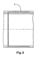
- Figure 3 illustrates a deformable and plastically expandable dovetail joint 6 for joining sections of the deformable tubular metal patch.
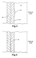
- Figure 4 is a longitudinal cross sectional view showing a tubular metal patch 10 in position in a cased wellbore 11 prior to expansion of the patch against the casing wall 12.
- the patch 10 is provided with a section 13 of decreased internal diameter and hence increased wall thickness.
- Figure 5 shows the patch after a metal to metal ring seal 14 has been formed at the location of the section of decreased internal diameter.
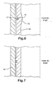
- Figure 6 illustrates a modified patch of the type shown in Figures 4 and 5 wherein the section 13 of patch of decreased internal diameter and hence increased wall thickness is provided with an external groove 17 adapted to receive an O-ring, 15, formed from an elastomeric material.
- Figure 7 shows the patch in annular (or ring) sealing engagement with the walls of a wellbore 16 which may be either a cased or lined wellbore or an open hole wellbore.
- a production tubing 20 having a restriction 21 is positioned within the casing 22 of a wellbore.
- a liner 23 is hung from the casing 22 via a casing hanger 24.
- An apparatus for deploying a tubular metal patch 25 is lowered into the wellbore through the production tubing 20 suspended from a wireline 26.
- the apparatus comprises a connector 27, a controller 28, a first electric motor 29 for actuating a screw mechanism (not shown) for radially extending and retracting slips 30, and an expander tool comprising a jack mechanism 31 for radially extending and retracting rollers 32, and a rotatable shaft 33 that extends from a second electric motor 34 through patch 25 to a third electric motor 35.
- the second electric motor 34 actuates the jack mechanism 31 and a means (not shown) for driving the rotatable shaft 33 while the third electric motor 35 actuates a screw mechanism (not shown) for moving the rollers 32 in a longitudinal direction within the patch 25.
- the slips 30 are shown in their radially extended position gripping the tubular metal patch 25.
- the shaft 33 is rotated and the rollers 32 are gradually radially extended to plastically expand the patch until the patch forms an annular fluid tight seal with the wall of the liner 23.
- the third electric motor 35 actuates the screw mechanism to move the rollers upwardly and downwardly within the patch 25 thereby extending the annular seal.
- Figure 9 shows the result of this operation with a section of the patch 25 plastically expanded to form an annular seal 36 with the wall of liner 23.
- the rollers 32 and slips 30 are retracted before moving the expansion tool to a new position in the patch and radially extending the slips 30 to grip the interior wall of the patch.
- the expansion tool is then actuated to plastically expand the new section of patch, as discussed above.
- the third electric motor 35 may be provided with a "steady" having a centraliser 37 that engages with the liner 23. This operation may be repeated until the entire lower section of the patch has been plastically expanded against the wellbore wall.
- the apparatus may then be moved upwardly through the wellbore until the expander tool is located in the upper 38 unexpanded part of the patch 25.
- the slips 30 are then radially extended to engage with the wall of the casing 22 and the expander tool actuated as described above to plastically expand the upper section 38 of the tubular metal patch.
- the rollers 32 and slips 30 may then be retracted and the apparatus removed from the wellbore by pulling the wireline leaving behind the plastically expanded patch in annular sealing engagement with the wall of the liner 23.
- the apparatus of the present invention may also be deployed in a deviated well, for example, a side track or lateral well. If necessary, the apparatus may be provided with a tractor to assist in moving the tubular patch through the deviated well.
Landscapes
- Geology (AREA)
- Life Sciences & Earth Sciences (AREA)
- Engineering & Computer Science (AREA)
- Mining & Mineral Resources (AREA)
- Environmental & Geological Engineering (AREA)
- Fluid Mechanics (AREA)
- Physics & Mathematics (AREA)
- General Life Sciences & Earth Sciences (AREA)
- Geochemistry & Mineralogy (AREA)
- Earth Drilling (AREA)
- Valve Device For Special Equipments (AREA)
- Drilling And Boring (AREA)
- Gasket Seals (AREA)
Claims (27)
- Vorrichtung zum plastischen Ausdehnen eines röhrenförmigen Flickens in einem Bohrloch, umfassend:(a) eine Greifeinrichtung, die den röhrenförmigen Flicken in dem Bohrloch an der gewünschten Stelle halten kann, umfassend mindestens ein radial ausziehbares Greifteil (30) zum Greifen der Innenwand des röhrenförmigen Flickens (25) und ein mechanisches Mittel zum radialen Ausziehen des/der Greifteils/Greifteile;(b) ein drehbares Dehnwerkzeug, das in dem röhrenförmigen Flicken (25) angebracht werden kann, umfassend mehrere Dehnelemente (32), die radial davon ausziehbar und so angepaßt sind, daß sie sich mit der Innenwand des röhrenförmigen Flickens (25) verbinden, und ein mechanisches Mittel (31) zum radialen Ausziehen der Dehnelemente (32); und(c) mindestens einen elektrischen Motor (29, 34), der dem mechanischen Mittel Antriebskraft zuführen kann, um so das/die Greifteil(e) der Greifeinrichtung radial auszuziehen, dem mechanischen Mittel (31) Antriebskraft zum radialen Ausziehen der Dehnelemente (32) des Dehnwerkzeugs zuzuführen und das Dehnwerkzeug zu drehen.
- Vorrichtung nach Anspruch 1, die an einer Drahtleitung (26) oder einem elektrischen Schlangenrohr aufgehängt ist.
- Vorrichtung nach den Ansprüchen 1 oder 2, wobei das mechanische Mittel zum radialen Ausziehen des/der Greifteils/Greifteile der Greifeinrichtung und/oder zum radialen Ausziehen der Dehnelemente des Dehnwerkzeugs ein Hebemechanismus oder ein Kegelverdrängungsmechanismus ist.
- Vorrichtung nach einem der vorhergehenden Ansprüche, wobei die Dehnelemente (32) des Dehnwerkzeugs Rollen oder Kugeln sind.
- Vorrichtung nach einem der vorhergehenden Ansprüche, wobei das Dehnwerkzeug mit einem weiteren mechanischen Mittel zum Bewegen der Dehnelemente (32) des Dehnwerkzeugs längs in dem röhrenförmigen Flicken (25) ausgestattet ist und der mindestens eine elektrische Motor (c) (35) auch dem weiteren mechanischen Mittel Antriebskraft zuführt.
- Vorrichtung nach einem der vorhergehenden Ansprüche, wobei das Dehnwerkzeug mit einem Antriebsmittel (33) zum Drehen des Dehnwerkzeugs ausgestattet ist und der mindestens eine elektrische Motor (c) (34) auch das Antriebsmittel (33) dreht.
- Vorrichtung nach Anspruch 6, wobei das mechanische Mittel zum radialen Ausziehen des/der Greifteils/Greifteile der Greifeinrichtung, das mechanische Mittel zum radialen Ausziehen der Dehnelemente des Dehnwerkzeugs, das mechanische Mittel zum Bewegen der Dehnelemente des Dehnwerkzeugs längs in dem röhrenförmigen Flicken und das Antriebsmittel zum Drehen des Dehnwerkzeugs mit zweckspezifischen elektrischen Motoren (29, 34, 35) ausgestattet sind.
- Verfahren zum Abdichten eines Loches in einem Rohr in einem Bohrloch oder zum Abdichten eines offenen Zwischenraumes eines Bohrloches, umfassend:(A) das Einführen eines röhrenförmigen Flickensystems in das Bohrloch und Plazieren des Systems neben einem Loch in dem Rohr oder neben dem offenen Zwischenraum des Bohrloches, der abgedichtet werden soll, wobei das röhrenförmige Flickensystem einen röhrenförmigen Flicken (25) und eine Vorrichtung zum plastischen Dehnen des röhrenförmigen Flikkens umfaßt, umfassend (a) eine Greifeinrichtung, die den röhrenförmigen Flicken in dem Bohrloch an der gewünschten Stelle halten kann, umfassend mindestens ein radial ausziehbares Greifteil (30) zum Greifen der Innenwand des röhrenförmige Flickens (25), wenn der Flicken eingeführt wird und sich in dem Bohrloch an der gewünschten Stelle befindet, und ein mechanisches Mittel zum radialen Ausziehen des/der Greifteils/Greifteile; (b) ein drehbares Dehnwerkzeug, das in dem röhrenförmigen Flicken angebracht ist, umfassend mehrere Dehnelemente (32), die radial davon ausziehbar und so angepaßt sind, daß sie sich mit der Innenwand des röhrenförmigen Flickens (25) verbinden, und ein mechanisches Mittel (31) zum radialen Ausziehen der Dehnelemente (32); und (c) mindestens einen elektrischen Motor (29, 34), der dem mechanischen Mittel Antriebskraft zuführen kann, um so das/die Greifteil(e) der Greifeinrichtung radial auszuziehen, dem mechanischen Mittel (31) Antriebskraft zum radialen Ausziehen der Dehnelemente (32) des Dehnwerkzeugs zuzuführen und das Dehnwerkzeug zu drehen; und(B) Betätigen des Dehnwerkzeugs, um den röhrenförmigen Flicken so auszudehnen, daß das Loch in dem Rohr oder der offene Teil des Bohrloches abgedichtet wird.
- Verfahren nach Anspruch 8, wobei das mindestens eine radial ausziehbare Greifteil mit der Innenwand des röhrenförmigen Flickens (25) an dessen unterem Ende verbunden ist und darin eingreift.
- Verfahren nach den Ansprüchen 8 oder 9, wobei ein Teil des Flickens (25) durch Drehen des Dehnwerkzeugs und Betätigen des mechanischen Mittels (31) zum radialen Ausziehen der Dehnelemente (32) des Dehnwerkzeugs plastisch ausgedehnt wird, so daß die Dehnelemente (32) mit der Innenwand des Flickens (25) verbunden sind und der Flicken (25) unter Bildung einer flüssigkeitsdichten, ringförmigen (oder Ring-) Dichtung mit der Wand des Rohres oder mit dem offenen Bohrloch plastisch ausgedehnt wird.
- Verfahren nach Anspruch 10, wobei das Dehnwerkzeug ein weiteres mechanisches Mittel zum Bewegen der Dehnelemente in Längsrichtung in dem Flicken (25) umfaßt, und das weitere mechanische Mittel unter Bewegung der Dehnelemente des Dehnwerkzeugs längs durch den Flicken elektrisch betätigt wird, wodurch die ringförmige Dichtung ausgezogen oder der gesamte röhrenförmige Flicken plastisch ausgedehnt wird.
- Verfahren nach Anspruch 10 oder 11, wobei nach dem Bilden der ringförmigen Dichtung die radial ausziehbaren Dehnelemente (32) des Dehnwerkzeugs und das/die radial ausziehbare(n) Greifteil(e) (30) der Greifeinrichtung eingezogen werden und die Vorrichtung zur Bildung einer weiteren ringförmigen Dichtung zu einer neuen Stelle in dem Flicken (25) bewegt wird.
- Verfahren nach Anspruch 12, wobei mindestens eine ringförmige Dichtung über dem Loch in dem Rohr oder über dem offenen Zwischenraum des Bohrloches und mindestens eine ringförmige Dichtung unter dem Loch in dem Rohr oder unter dem offenen Zwischenraum des Bohrloches gebildet wird.
- Verfahren nach einem der Ansprüche 8 bis 13, wobei der Flicken (25) in dem Bohrloch an einer Stelle unter einer Verengung (21), D1, eingesetzt wird, und der Flicken ein Metallrohr umfaßt, das in ein unregelmäßig geformtes Rohr mit einem maximalen äußeren Querschnittsausmaß, D2, das kleiner ist als D1, verformt ist, und wobei, nachdem der Flicken durch die Verengung zu der gewünschten Stelle in dem Bohrloch geführt wurde, das Dehnwerkzeug zum Zurückbilden des Flickens in ein im wesentlichen regelmäßig geformtes Rohr mit einem Außendurchmesser, D3, der größer ist als D1, und zum plastischen Ausdehnen mindestens eines Teils des zurückgebildeten Rohres auf einen Außendurchmesser, D4, betätigt wird, um so eine flüssigkeitsdichte ringförmige Dichtung mit der Wand des Rohres oder der Wand des offenen Bohrloches zu bilden, wobei das Expansionsverhältnis [(D4 - D3) / D3] x 100 des zurückgebildeten Rohres im Bereich von 10 bis 30 % liegt.
- Verfahren nach Anspruch 14, wobei das röhrenförmigen Flickensystem durch das Steigrohr (20) zu der ausgewählten Stelle in dem Bohrloch geführt wird.
- Verfahren nach Anspruch 14 oder 15, wobei der verformte Flicken ein längs gewelltes Rohr ist.
- Verfahren nach einem der Ansprüche 8 bis 16, wobei der röhrenförmige Metallflicken mit einem äußeren elastischen Dichtungsteil ausgestattet ist, um so eine bessere Dichtung mit dem Rohr oder mit der Wand des offenen Bohrloches bereitzustellen.
- Verfahren nach einem der Ansprüche 8 bis 17, wobei der Flicken aus mehreren röhrenförmigen Metallabschnitten gefertigt ist, wobei die Abschnitte des Flickens unter Verwendung verformbarer und gegebenenfalls plastisch ausdehnbarer Gelenke miteinander verbunden sind.
- Verfahren nach einem der Ansprüche 8 bis 18, wobei mindestens ein Abschnitt des Flikkens im Vergleich zu der Wanddicke, t2, der benachbarten Abschnitte des Flickens eine stärkere Wanddicke (13), t1, aufweist (d. h. t1 > t2), und wobei das drehbare Dehnwerkzeug zum plastischen Ausdehnen des mindestens einen Abschnittes des Metallrohres mit der stärkeren Wanddicke betätigt wird, um so eine ringförmige Dichtung mit dem Rohr oder dem offenen Bohrloch zu bilden.
- Verfahren nach Anspruch 19, wobei der/die Abschnitt(e) des Metallrohres mit der stärkeren Wanddicke (13), t1, mit einer ringförmigen Aussparung oder Fuge (17) auf der Außenfläche mit einem darin befindlichen ringförmigen elastischen Dichtungsring (15) ausgestattet ist/sind, und wobei das mechanische Mittel zum radialen Ausziehen der Dehnelemente bewegt wird, um den mindestens einen Abschnitt des Metallrohres mit der stärkeren Wanddikke (13), t1, plastisch auszudehnen, wodurch der ringförmige elastische Dichtungsring unter Bildung einer flüssigkeitsdichten ringförmigen Dichtung gegen das Rohr oder gegen die Wand des offenen Bohrloches gedrängt wird.
- Verfahren nach Anspruch 8 zum Abdichten eines Loches in einem Rohr in einem Bohrloch oder zum Abdichten eines offenen Zwischenraumes eines Bohrloches, umfassend:(A) das Einführen eines röhrenförmigen Flickens (25) in das Bohrloch und Plazieren des röhrenförmigen Flickens (25) neben dem Loch in dem Rohr oder neben dem offenen Zwischenraum des Bohrloches;(B) (i) das plastische Ausdehnen eines ersten Teils eines röhrenförmigen Flickens (25) über dem Loch in dem Rohr oder über dem offenen Zwischenraum des Bohrloches in ringförmigem Dichtungseingriff mit dem Rohr oder dem offenen Bohrloch zur Bildung einer ersten ringförmigen Dichtung und (ii) das plastische Ausdehnen eines zweiten Teils des röhrenförmigen Flickens (25) unter dem Loch in dem Rohr oder unter dem offenen Zwischenraum des Bohrloches in ringförmigem Dichtungseingriff mit dem Rohr oder dem offenen Bohrloch zur Bildung einer zweiten ringförmigen Dichtung, wodurch das Loch in dem Rohr oder dem offen Zwischenraum des Bohrloches abgedichtet wird.
- Verfahren nach Anspruch 21, wobei weitere Teile des röhrenförmigen Flickens (25) zur Bildung weiterer ringförmiger Dichtungen in ringförmigem Dichtungseingriff mit dem Rohr oder dem offenen Bohrloch plastisch ausgedehnt werden.
- Verfahren nach Anspruch 21 oder 22, wobei der röhrenförmige Flicken (25) ein röhrenförmiger Abschnitt eines Sandsiebes ist, daß mindestens einen röhrenförmigen Abschnitt und mindestens einen Siebabschnitt umfaßt.
- Verfahren nach Anspruch 21 oder 22, wobei der röhrenförmige Flicken (25) in dem Bohrloch an einer Stelle unter einer Verengung (21), D1, eingesetzt wird und der Flicken ein Metallrohr umfaßt, das in ein unregelmäßig geformtes Rohr mit einem maximalen äußeren Querschnittsausmaß, D2, das kleiner ist als D1, verformt wurde, und wobei, nachdem der Flicken durch die Verengung zu der gewünschten Stelle in dem Bohrloch geführt worden ist, der Flicken in ein im wesentlichen regelmäßig geformtes Rohr mit einem Außendurchmesser, D3, der größer ist als D1, zurückgebildet wird, und die erste und zweite ringförmige Dichtung durch plastisches Ausdehnen des ersten und zweiten Teils des zurückgebildeten Rohres auf einen Außendurchmesser, D4, gebildet werden, wobei das Expansionsverhältnis [(D4 - D3) / D3] x 100 des ersten und zweiten Teils des zurückgebildeten Rohres im Bereich von 10 bis 30 % liegt.
- Verfahren nach einem der vorhergehenden Ansprüche, wobei das erste, zweite und gegebenenfalls weitere Teil(e) des Flickens, das/die unter Bildung der ringförmigen Dichtungen mit dem Rohr oder dem offenen Bohrloch plastisch ausgedehnt wurde(n) im Vergleich zu der Wanddicke, t2, der benachbarten Teile des Flickens eine stärkere Wanddicke, t1, aufweist/auf weisen.
- Verfahren nach einem der Ansprüche 21 bis 25, wobei die Ringdichtungen unter Verwendung der Vorrichtung aus einem der Ansprüche 1 bis 7 gebildet werden.
- Verfahren nach Anspruch 8, wobei der röhrenförmige Flicken ein Linerstrang ist, der Linerstrang so in dem Bohrloch plaziert wird, daß ein oberer Abschnitt des Linerstranges einen unteren Abschnitt eines gestützten oder gefütterten Zwischenraumes des Bohrloches überlappt, und das Dehnwerkzeug so betätigt wird, daß die Dehnelemente einen Teil des oberen Abschnitts des Linerstranges unter Bildung einer ringförmigen Dichtung zwischen dem oberen Abschnitt des Linerstranges und dem unteren Abschnitt des gestützten oder gefütterten Zwischenraumes des Bohrloches plastisch ausdehnen, und gegebenenfalls Betätigen des Dehnwerkzeuges zur Bildung weiterer ringförmiger Dichtungen zwischen dem oberen Abschnitt des Linerstranges und dem unteren Abschnitt des gestützten oder gefütterten Zwischenraumes des Bohrloches.
Applications Claiming Priority (2)
| Application Number | Priority Date | Filing Date | Title |
|---|---|---|---|
| GBGB0315251.9A GB0315251D0 (en) | 2003-06-30 | 2003-06-30 | Device |
| PCT/GB2004/002763 WO2005003511A1 (en) | 2003-06-30 | 2004-06-28 | Apparatus and method for sealing a wellbore |
Publications (2)
| Publication Number | Publication Date |
|---|---|
| EP1639229A1 EP1639229A1 (de) | 2006-03-29 |
| EP1639229B1 true EP1639229B1 (de) | 2008-04-30 |
Family
ID=27676342
Family Applications (1)
| Application Number | Title | Priority Date | Filing Date |
|---|---|---|---|
| EP04743112A Expired - Lifetime EP1639229B1 (de) | 2003-06-30 | 2004-06-28 | Vorrichtung und verfahren zur abdichtung eines bohrloches |
Country Status (6)
| Country | Link |
|---|---|
| US (1) | US20070095532A1 (de) |
| EP (1) | EP1639229B1 (de) |
| AT (1) | ATE393867T1 (de) |
| DE (1) | DE602004013442T2 (de) |
| GB (1) | GB0315251D0 (de) |
| WO (1) | WO2005003511A1 (de) |
Families Citing this family (58)
| Publication number | Priority date | Publication date | Assignee | Title |
|---|---|---|---|---|
| US6464003B2 (en) | 2000-05-18 | 2002-10-15 | Western Well Tool, Inc. | Gripper assembly for downhole tractors |
| US7121351B2 (en) * | 2000-10-25 | 2006-10-17 | Weatherford/Lamb, Inc. | Apparatus and method for completing a wellbore |
| US7090025B2 (en) | 2000-10-25 | 2006-08-15 | Weatherford/Lamb, Inc. | Methods and apparatus for reforming and expanding tubulars in a wellbore |
| US8245796B2 (en) * | 2000-12-01 | 2012-08-21 | Wwt International, Inc. | Tractor with improved valve system |
| GB0311721D0 (en) | 2003-05-22 | 2003-06-25 | Weatherford Lamb | Tubing connector |
| CA2471051C (en) | 2003-06-16 | 2007-11-06 | Weatherford/Lamb, Inc. | Borehole tubing expansion |
| US7392859B2 (en) * | 2004-03-17 | 2008-07-01 | Western Well Tool, Inc. | Roller link toggle gripper and downhole tractor |
| US7306044B2 (en) * | 2005-03-02 | 2007-12-11 | Halliburton Energy Services, Inc. | Method and system for lining tubulars |
| DE602005022277D1 (de) | 2005-04-29 | 2010-08-26 | Schlumberger Technology Bv | Vorrichtung und Verfahren zum Aufweiten von rohrförmigen Elementen |
| US7624808B2 (en) | 2006-03-13 | 2009-12-01 | Western Well Tool, Inc. | Expandable ramp gripper |
| US7748476B2 (en) * | 2006-11-14 | 2010-07-06 | Wwt International, Inc. | Variable linkage assisted gripper |
| CA2684681C (en) | 2007-04-26 | 2015-04-14 | Welltec A/S | Cladding method and expansion tool |
| US7770667B2 (en) | 2007-06-14 | 2010-08-10 | Wwt International, Inc. | Electrically powered tractor |
| US9303477B2 (en) | 2009-04-02 | 2016-04-05 | Michael J. Harris | Methods and apparatus for cementing wells |
| US8684096B2 (en) * | 2009-04-02 | 2014-04-01 | Key Energy Services, Llc | Anchor assembly and method of installing anchors |
| US8485278B2 (en) * | 2009-09-29 | 2013-07-16 | Wwt International, Inc. | Methods and apparatuses for inhibiting rotational misalignment of assemblies in expandable well tools |
| WO2011056163A1 (en) * | 2009-11-04 | 2011-05-12 | 2M-Tek, Inc. | Apparatus & method for running tubulars |
| DK2423428T3 (da) * | 2010-08-31 | 2013-08-26 | Welltec As | Forseglingssystem |
| US9447648B2 (en) | 2011-10-28 | 2016-09-20 | Wwt North America Holdings, Inc | High expansion or dual link gripper |
| US9169724B2 (en) | 2012-02-23 | 2015-10-27 | Halliburton Energy Services, Inc. | Expandable conical tubing run through production tubing and into open hole |
| US10612349B2 (en) * | 2013-11-06 | 2020-04-07 | Halliburton Energy Services, Inc. | Downhole casing patch |
| US9488020B2 (en) | 2014-01-27 | 2016-11-08 | Wwt North America Holdings, Inc. | Eccentric linkage gripper |
| CA3171397C (en) | 2014-02-27 | 2025-07-08 | Shell Internationale Research Maatschappij B.V. | METHOD AND SYSTEM FOR LINING A TUBULAR ELEMENT |
| US9494020B2 (en) * | 2014-04-09 | 2016-11-15 | Weatherford Technology Holdings, Llc | Multiple diameter expandable straddle system |
| RU2548269C1 (ru) * | 2014-05-21 | 2015-04-20 | Открытое акционерное общество "Татнефть" им. В.Д. Шашина | Способ крепления зоны осложнения скважины профильным перекрывателем |
| US10280698B2 (en) * | 2016-10-24 | 2019-05-07 | General Electric Company | Well restimulation downhole assembly |
| AU2017439376B2 (en) | 2017-11-13 | 2023-06-01 | Halliburton Energy Services, Inc. | Swellable metal for non-elastomeric O-rings, seal stacks, and gaskets |
| EP3517728A1 (de) * | 2018-01-25 | 2019-07-31 | Welltec Oilfield Solutions AG | Kabelgeführtes eingriffswerkzeug für ein bohrloch |
| CA3088190C (en) | 2018-02-23 | 2022-10-04 | Halliburton Energy Services, Inc. | Swellable metal for swell packer |
| WO2019227195A1 (en) * | 2018-06-01 | 2019-12-05 | Winterhawk Well Abandonment Ltd. | Casing expander for well abandonment |
| NO20210921A1 (en) * | 2019-01-21 | 2021-07-21 | Saltel Ind | System and methodology for through tubing patching |
| GB2593614B (en) | 2019-02-22 | 2022-12-07 | Halliburton Energy Services Inc | An expanding metal sealant for use with multilateral completion systems |
| US11261693B2 (en) | 2019-07-16 | 2022-03-01 | Halliburton Energy Services, Inc. | Composite expandable metal elements with reinforcement |
| WO2021021203A1 (en) | 2019-07-31 | 2021-02-04 | Halliburton Energy Services, Inc. | Methods to monitor a metallic sealant deployed in a wellbore, methods to monitor fluid displacement, and downhole metallic sealant measurement systems |
| NO20211578A1 (en) | 2019-08-06 | 2021-12-22 | Halliburton Energy Services Inc | Expandable metal gas lift mandrel plug |
| US12480373B2 (en) | 2019-11-13 | 2025-11-25 | Halliburton Energy Services, Inc. | Actuating a downhole device with a reactive metal |
| US11255160B2 (en) * | 2019-12-09 | 2022-02-22 | Saudi Arabian Oil Company | Unblocking wellbores |
| US11761290B2 (en) | 2019-12-18 | 2023-09-19 | Halliburton Energy Services, Inc. | Reactive metal sealing elements for a liner hanger |
| NO20220612A1 (en) | 2020-01-17 | 2022-05-24 | Halliburton Energy Services Inc | Voltage to accelerate/decelerate expandable metal |
| GB2604814B (en) | 2020-01-17 | 2024-10-09 | Halliburton Energy Services Inc | Heaters to accelerate setting of expandable metal |
| NO20220804A1 (en) | 2020-02-28 | 2022-07-15 | Halliburton Energy Services Inc | Textured surfaces of expanding metal for centralizer, mixing, and differential sticking |
| GB2611689B (en) | 2020-08-13 | 2024-06-26 | Halliburton Energy Services Inc | Expandable metal displacement plug |
| US11761293B2 (en) | 2020-12-14 | 2023-09-19 | Halliburton Energy Services, Inc. | Swellable packer assemblies, downhole packer systems, and methods to seal a wellbore |
| US11572749B2 (en) | 2020-12-16 | 2023-02-07 | Halliburton Energy Services, Inc. | Non-expanding liner hanger |
| MX2023009992A (es) | 2021-04-12 | 2023-09-06 | Halliburton Energy Services Inc | Metal expandible como respaldo de elementos elastomericos. |
| US11578498B2 (en) | 2021-04-12 | 2023-02-14 | Halliburton Energy Services, Inc. | Expandable metal for anchoring posts |
| US11879304B2 (en) | 2021-05-17 | 2024-01-23 | Halliburton Energy Services, Inc. | Reactive metal for cement assurance |
| GB2617770B (en) | 2021-05-21 | 2025-12-03 | Halliburton Energy Services Inc | A wellbore anchor including one or more activation chambers |
| BR112023020413A2 (pt) | 2021-05-28 | 2023-12-12 | Halliburton Energy Services Inc | Ferramenta de fundo de poço, método para vedação dentro de um sistema de poço, e, sistema de poço |
| CA3213939A1 (en) | 2021-05-28 | 2022-12-01 | Stephen Michael Greci | Individual separate chunks of expandable metal |
| CA3216086A1 (en) | 2021-05-29 | 2022-12-08 | Halliburton Energy Services, Inc. | Using expandable metal as an alternate to existing metal to metal seals |
| AU2021448382A1 (en) * | 2021-05-29 | 2023-09-28 | Halliburton Energy Services, Inc. | Self activating seal assembly backup |
| US11634967B2 (en) | 2021-05-31 | 2023-04-25 | Winterhawk Well Abandonment Ltd. | Method for well remediation and repair |
| US11697915B2 (en) | 2021-06-01 | 2023-07-11 | Halliburton Energy Services, Inc. | Expanding metal used in forming support structures |
| WO2023059312A1 (en) | 2021-10-05 | 2023-04-13 | Halliburton Energy Services, Inc. | Expandable metal sealing/anchoring tool |
| US12305459B2 (en) | 2022-06-15 | 2025-05-20 | Halliburton Energy Services, Inc. | Sealing/anchoring tool employing an expandable metal circlet |
| US12385340B2 (en) | 2022-12-05 | 2025-08-12 | Halliburton Energy Services, Inc. | Reduced backlash sealing/anchoring assembly |
| US12612843B2 (en) | 2023-12-26 | 2026-04-28 | Halliburton Energy Services, Inc. | Mechanical support for expandable liner hanger |
Family Cites Families (20)
| Publication number | Priority date | Publication date | Assignee | Title |
|---|---|---|---|---|
| US3203451A (en) | 1962-08-09 | 1965-08-31 | Pan American Petroleum Corp | Corrugated tube for lining wells |
| US3489220A (en) | 1968-08-02 | 1970-01-13 | J C Kinley | Method and apparatus for repairing pipe in wells |
| US4624306A (en) * | 1983-06-20 | 1986-11-25 | Traver Tool Company | Downhole mobility and propulsion apparatus |
| US6142230A (en) * | 1996-11-14 | 2000-11-07 | Weatherford/Lamb, Inc. | Wellbore tubular patch system |
| US5785120A (en) | 1996-11-14 | 1998-07-28 | Weatherford/Lamb, Inc. | Tubular patch |
| EP1012441B1 (de) * | 1997-09-09 | 2004-02-18 | NOBILEAU, Philippe | Verfahren und vorrichtung zum installieren einer lateralen abzweigung von einer hauptbohrung |
| CA2273568C (en) | 1998-06-04 | 2007-08-14 | Philip Head | A method of installing a casing in a well and apparatus therefor |
| US6739392B2 (en) * | 1998-12-07 | 2004-05-25 | Shell Oil Company | Forming a wellbore casing while simultaneously drilling a wellbore |
| CA2306656C (en) * | 1999-04-26 | 2006-06-06 | Shell Internationale Research Maatschappij B.V. | Expandable connector for borehole tubes |
| CA2383231C (en) * | 1999-07-09 | 2009-01-27 | Enventure Global Technology | Two-step radial expansion |
| WO2001018353A1 (en) * | 1999-09-06 | 2001-03-15 | E2 Tech Limited | Expandable downhole tubing |
| US7048067B1 (en) * | 1999-11-01 | 2006-05-23 | Shell Oil Company | Wellbore casing repair |
| US6598678B1 (en) * | 1999-12-22 | 2003-07-29 | Weatherford/Lamb, Inc. | Apparatus and methods for separating and joining tubulars in a wellbore |
| US6578630B2 (en) * | 1999-12-22 | 2003-06-17 | Weatherford/Lamb, Inc. | Apparatus and methods for expanding tubulars in a wellbore |
| GB2359571B (en) | 2000-02-28 | 2004-03-17 | Philip Head | Submersible pumps |
| US6695054B2 (en) * | 2001-01-16 | 2004-02-24 | Schlumberger Technology Corporation | Expandable sand screen and methods for use |
| GB0026063D0 (en) * | 2000-10-25 | 2000-12-13 | Weatherford Lamb | Downhole tubing |
| US6648071B2 (en) * | 2001-01-24 | 2003-11-18 | Schlumberger Technology Corporation | Apparatus comprising expandable bistable tubulars and methods for their use in wellbores |
| GB2388858B (en) * | 2001-01-24 | 2004-05-12 | Schlumberger Holdings | Methods for connecting expandable tubulars |
| US6775894B2 (en) | 2001-07-11 | 2004-08-17 | Aera Energy, Llc | Casing patching tool |
-
2003
- 2003-06-30 GB GBGB0315251.9A patent/GB0315251D0/en not_active Ceased
-
2004
- 2004-06-28 US US10/561,901 patent/US20070095532A1/en not_active Abandoned
- 2004-06-28 WO PCT/GB2004/002763 patent/WO2005003511A1/en not_active Ceased
- 2004-06-28 AT AT04743112T patent/ATE393867T1/de not_active IP Right Cessation
- 2004-06-28 EP EP04743112A patent/EP1639229B1/de not_active Expired - Lifetime
- 2004-06-28 DE DE602004013442T patent/DE602004013442T2/de not_active Expired - Fee Related
Also Published As
| Publication number | Publication date |
|---|---|
| WO2005003511A1 (en) | 2005-01-13 |
| US20070095532A1 (en) | 2007-05-03 |
| DE602004013442D1 (de) | 2008-06-12 |
| DE602004013442T2 (de) | 2009-06-04 |
| EP1639229A1 (de) | 2006-03-29 |
| ATE393867T1 (de) | 2008-05-15 |
| GB0315251D0 (en) | 2003-08-06 |
Similar Documents
| Publication | Publication Date | Title |
|---|---|---|
| EP1639229B1 (de) | Vorrichtung und verfahren zur abdichtung eines bohrloches | |
| CA2442891C (en) | Expandable connection for use with a swelling elastomer | |
| US6668930B2 (en) | Method for installing an expandable coiled tubing patch | |
| US6585053B2 (en) | Method for creating a polished bore receptacle | |
| US7228911B2 (en) | Apparatus for and method of radial expansion of a tubular member | |
| US6742598B2 (en) | Method of expanding a sand screen | |
| CA2472793C (en) | Connection of downhole tubulars by expansion | |
| US7546886B2 (en) | Method of creating a borehole in an earth formation | |
| NO344339B1 (en) | Expandable liner hanger with high axial load capacity | |
| WO2003001026A1 (en) | Tie back for use with expandable tubulars | |
| EP1702133B1 (de) | Verfahren zum bohren und verrohren eines bohrlochs | |
| WO2010009262A2 (en) | Interventionless set packer and setting method for same | |
| GB2467260A (en) | Methods and apparatus for expanding a tubular | |
| US20100088879A1 (en) | Apparatus and methods for expanding tubular elements | |
| US20030183395A1 (en) | System and method for preventing sand production into a well casing having a perforated interval | |
| GB2525096A (en) | Multiple diameter expandable straddle system | |
| US8522866B2 (en) | System and method for anchoring an expandable tubular to a borehole wall | |
| EP2202383A1 (de) | Verfahren zur Erweiterung eines röhrenförmigen Elements in einem Bohrloch | |
| NO341850B1 (en) | Packer assembly, barrel slip for a packer assembly, and method for diverting axial loading to a wellbore from a packer assembly |
Legal Events
| Date | Code | Title | Description |
|---|---|---|---|
| PUAI | Public reference made under article 153(3) epc to a published international application that has entered the european phase |
Free format text: ORIGINAL CODE: 0009012 |
|
| 17P | Request for examination filed |
Effective date: 20060118 |
|
| AK | Designated contracting states |
Kind code of ref document: A1 Designated state(s): AT BE BG CH CY CZ DE DK EE ES FI FR GB GR HU IE IT LI LU MC NL PL PT RO SE SI SK TR |
|
| DAX | Request for extension of the european patent (deleted) | ||
| 17Q | First examination report despatched |
Effective date: 20060509 |
|
| 17Q | First examination report despatched |
Effective date: 20060509 |
|
| GRAP | Despatch of communication of intention to grant a patent |
Free format text: ORIGINAL CODE: EPIDOSNIGR1 |
|
| GRAS | Grant fee paid |
Free format text: ORIGINAL CODE: EPIDOSNIGR3 |
|
| GRAA | (expected) grant |
Free format text: ORIGINAL CODE: 0009210 |
|
| AK | Designated contracting states |
Kind code of ref document: B1 Designated state(s): AT BE BG CH CY CZ DE DK EE ES FI FR GB GR HU IE IT LI LU MC NL PL PT RO SE SI SK TR |
|
| REG | Reference to a national code |
Ref country code: GB Ref legal event code: FG4D |
|
| REG | Reference to a national code |
Ref country code: CH Ref legal event code: EP |
|
| REG | Reference to a national code |
Ref country code: IE Ref legal event code: FG4D Free format text: LANGUAGE OF EP DOCUMENT: FRENCH |
|
| REF | Corresponds to: |
Ref document number: 602004013442 Country of ref document: DE Date of ref document: 20080612 Kind code of ref document: P |
|
| PG25 | Lapsed in a contracting state [announced via postgrant information from national office to epo] |
Ref country code: SI Free format text: LAPSE BECAUSE OF FAILURE TO SUBMIT A TRANSLATION OF THE DESCRIPTION OR TO PAY THE FEE WITHIN THE PRESCRIBED TIME-LIMIT Effective date: 20080430 |
|
| PG25 | Lapsed in a contracting state [announced via postgrant information from national office to epo] |
Ref country code: ES Free format text: LAPSE BECAUSE OF FAILURE TO SUBMIT A TRANSLATION OF THE DESCRIPTION OR TO PAY THE FEE WITHIN THE PRESCRIBED TIME-LIMIT Effective date: 20080810 Ref country code: PT Free format text: LAPSE BECAUSE OF FAILURE TO SUBMIT A TRANSLATION OF THE DESCRIPTION OR TO PAY THE FEE WITHIN THE PRESCRIBED TIME-LIMIT Effective date: 20080930 Ref country code: BG Free format text: LAPSE BECAUSE OF FAILURE TO SUBMIT A TRANSLATION OF THE DESCRIPTION OR TO PAY THE FEE WITHIN THE PRESCRIBED TIME-LIMIT Effective date: 20080730 Ref country code: FI Free format text: LAPSE BECAUSE OF FAILURE TO SUBMIT A TRANSLATION OF THE DESCRIPTION OR TO PAY THE FEE WITHIN THE PRESCRIBED TIME-LIMIT Effective date: 20080430 |
|
| PGFP | Annual fee paid to national office [announced via postgrant information from national office to epo] |
Ref country code: DE Payment date: 20080731 Year of fee payment: 5 Ref country code: NL Payment date: 20080624 Year of fee payment: 5 |
|
| NLR4 | Nl: receipt of corrected translation in the netherlands language at the initiative of the proprietor of the patent | ||
| PG25 | Lapsed in a contracting state [announced via postgrant information from national office to epo] |
Ref country code: PL Free format text: LAPSE BECAUSE OF FAILURE TO SUBMIT A TRANSLATION OF THE DESCRIPTION OR TO PAY THE FEE WITHIN THE PRESCRIBED TIME-LIMIT Effective date: 20080430 Ref country code: AT Free format text: LAPSE BECAUSE OF FAILURE TO SUBMIT A TRANSLATION OF THE DESCRIPTION OR TO PAY THE FEE WITHIN THE PRESCRIBED TIME-LIMIT Effective date: 20080430 |
|
| PGFP | Annual fee paid to national office [announced via postgrant information from national office to epo] |
Ref country code: FR Payment date: 20080617 Year of fee payment: 5 Ref country code: IT Payment date: 20080625 Year of fee payment: 5 |
|
| PGFP | Annual fee paid to national office [announced via postgrant information from national office to epo] |
Ref country code: GB Payment date: 20080627 Year of fee payment: 5 |
|
| PG25 | Lapsed in a contracting state [announced via postgrant information from national office to epo] |
Ref country code: MC Free format text: LAPSE BECAUSE OF NON-PAYMENT OF DUE FEES Effective date: 20080630 Ref country code: DK Free format text: LAPSE BECAUSE OF FAILURE TO SUBMIT A TRANSLATION OF THE DESCRIPTION OR TO PAY THE FEE WITHIN THE PRESCRIBED TIME-LIMIT Effective date: 20080430 Ref country code: CZ Free format text: LAPSE BECAUSE OF FAILURE TO SUBMIT A TRANSLATION OF THE DESCRIPTION OR TO PAY THE FEE WITHIN THE PRESCRIBED TIME-LIMIT Effective date: 20080430 Ref country code: SE Free format text: LAPSE BECAUSE OF FAILURE TO SUBMIT A TRANSLATION OF THE DESCRIPTION OR TO PAY THE FEE WITHIN THE PRESCRIBED TIME-LIMIT Effective date: 20080731 |
|
| REG | Reference to a national code |
Ref country code: CH Ref legal event code: PL |
|
| ET | Fr: translation filed | ||
| PG25 | Lapsed in a contracting state [announced via postgrant information from national office to epo] |
Ref country code: BE Free format text: LAPSE BECAUSE OF FAILURE TO SUBMIT A TRANSLATION OF THE DESCRIPTION OR TO PAY THE FEE WITHIN THE PRESCRIBED TIME-LIMIT Effective date: 20080430 Ref country code: RO Free format text: LAPSE BECAUSE OF FAILURE TO SUBMIT A TRANSLATION OF THE DESCRIPTION OR TO PAY THE FEE WITHIN THE PRESCRIBED TIME-LIMIT Effective date: 20080430 Ref country code: SK Free format text: LAPSE BECAUSE OF FAILURE TO SUBMIT A TRANSLATION OF THE DESCRIPTION OR TO PAY THE FEE WITHIN THE PRESCRIBED TIME-LIMIT Effective date: 20080430 |
|
| PLBE | No opposition filed within time limit |
Free format text: ORIGINAL CODE: 0009261 |
|
| STAA | Information on the status of an ep patent application or granted ep patent |
Free format text: STATUS: NO OPPOSITION FILED WITHIN TIME LIMIT |
|
| REG | Reference to a national code |
Ref country code: IE Ref legal event code: MM4A |
|
| 26N | No opposition filed |
Effective date: 20090202 |
|
| PG25 | Lapsed in a contracting state [announced via postgrant information from national office to epo] |
Ref country code: IE Free format text: LAPSE BECAUSE OF NON-PAYMENT OF DUE FEES Effective date: 20080628 Ref country code: EE Free format text: LAPSE BECAUSE OF FAILURE TO SUBMIT A TRANSLATION OF THE DESCRIPTION OR TO PAY THE FEE WITHIN THE PRESCRIBED TIME-LIMIT Effective date: 20080430 |
|
| PG25 | Lapsed in a contracting state [announced via postgrant information from national office to epo] |
Ref country code: CH Free format text: LAPSE BECAUSE OF NON-PAYMENT OF DUE FEES Effective date: 20080630 Ref country code: LI Free format text: LAPSE BECAUSE OF NON-PAYMENT OF DUE FEES Effective date: 20080630 |
|
| GBPC | Gb: european patent ceased through non-payment of renewal fee |
Effective date: 20090628 |
|
| NLV4 | Nl: lapsed or anulled due to non-payment of the annual fee |
Effective date: 20100101 |
|
| REG | Reference to a national code |
Ref country code: FR Ref legal event code: ST Effective date: 20100226 |
|
| PG25 | Lapsed in a contracting state [announced via postgrant information from national office to epo] |
Ref country code: FR Free format text: LAPSE BECAUSE OF NON-PAYMENT OF DUE FEES Effective date: 20090630 |
|
| PG25 | Lapsed in a contracting state [announced via postgrant information from national office to epo] |
Ref country code: GB Free format text: LAPSE BECAUSE OF NON-PAYMENT OF DUE FEES Effective date: 20090628 |
|
| PG25 | Lapsed in a contracting state [announced via postgrant information from national office to epo] |
Ref country code: DE Free format text: LAPSE BECAUSE OF NON-PAYMENT OF DUE FEES Effective date: 20100101 |
|
| PG25 | Lapsed in a contracting state [announced via postgrant information from national office to epo] |
Ref country code: NL Free format text: LAPSE BECAUSE OF NON-PAYMENT OF DUE FEES Effective date: 20100101 Ref country code: HU Free format text: LAPSE BECAUSE OF FAILURE TO SUBMIT A TRANSLATION OF THE DESCRIPTION OR TO PAY THE FEE WITHIN THE PRESCRIBED TIME-LIMIT Effective date: 20081101 Ref country code: CY Free format text: LAPSE BECAUSE OF FAILURE TO SUBMIT A TRANSLATION OF THE DESCRIPTION OR TO PAY THE FEE WITHIN THE PRESCRIBED TIME-LIMIT Effective date: 20080430 Ref country code: LU Free format text: LAPSE BECAUSE OF NON-PAYMENT OF DUE FEES Effective date: 20080628 |
|
| PG25 | Lapsed in a contracting state [announced via postgrant information from national office to epo] |
Ref country code: TR Free format text: LAPSE BECAUSE OF FAILURE TO SUBMIT A TRANSLATION OF THE DESCRIPTION OR TO PAY THE FEE WITHIN THE PRESCRIBED TIME-LIMIT Effective date: 20080430 |
|
| PG25 | Lapsed in a contracting state [announced via postgrant information from national office to epo] |
Ref country code: GR Free format text: LAPSE BECAUSE OF FAILURE TO SUBMIT A TRANSLATION OF THE DESCRIPTION OR TO PAY THE FEE WITHIN THE PRESCRIBED TIME-LIMIT Effective date: 20080731 |
|
| PG25 | Lapsed in a contracting state [announced via postgrant information from national office to epo] |
Ref country code: IT Free format text: LAPSE BECAUSE OF NON-PAYMENT OF DUE FEES Effective date: 20090628 |