EP1639302B1 - Method and system for tempering of product units in a tank, and application thereof - Google Patents
Method and system for tempering of product units in a tank, and application thereof Download PDFInfo
- Publication number
- EP1639302B1 EP1639302B1 EP20030816620 EP03816620A EP1639302B1 EP 1639302 B1 EP1639302 B1 EP 1639302B1 EP 20030816620 EP20030816620 EP 20030816620 EP 03816620 A EP03816620 A EP 03816620A EP 1639302 B1 EP1639302 B1 EP 1639302B1
- Authority
- EP
- European Patent Office
- Prior art keywords
- tank
- ice
- slurry
- water
- ice slurry
- Prior art date
- Legal status (The legal status is an assumption and is not a legal conclusion. Google has not performed a legal analysis and makes no representation as to the accuracy of the status listed.)
- Expired - Lifetime
Links
- 238000000034 method Methods 0.000 title claims abstract description 42
- 238000005496 tempering Methods 0.000 title abstract 2
- 239000002002 slurry Substances 0.000 claims abstract description 88
- XLYOFNOQVPJJNP-UHFFFAOYSA-N water Substances O XLYOFNOQVPJJNP-UHFFFAOYSA-N 0.000 claims abstract description 57
- 238000001816 cooling Methods 0.000 claims abstract description 27
- 239000000203 mixture Substances 0.000 claims abstract description 15
- 239000002245 particle Substances 0.000 claims abstract description 15
- 239000002826 coolant Substances 0.000 claims abstract description 5
- 150000003839 salts Chemical class 0.000 claims description 32
- 230000008569 process Effects 0.000 claims description 20
- 239000013078 crystal Substances 0.000 claims description 11
- 238000007710 freezing Methods 0.000 claims description 11
- 230000008014 freezing Effects 0.000 claims description 11
- FAPWRFPIFSIZLT-UHFFFAOYSA-M Sodium chloride Chemical compound [Na+].[Cl-] FAPWRFPIFSIZLT-UHFFFAOYSA-M 0.000 claims description 7
- 238000010438 heat treatment Methods 0.000 claims description 7
- 239000012267 brine Substances 0.000 claims description 6
- 235000013305 food Nutrition 0.000 claims description 6
- HPALAKNZSZLMCH-UHFFFAOYSA-M sodium;chloride;hydrate Chemical compound O.[Na+].[Cl-] HPALAKNZSZLMCH-UHFFFAOYSA-M 0.000 claims description 6
- 239000010802 sludge Substances 0.000 claims description 5
- 238000010411 cooking Methods 0.000 claims description 4
- 238000005086 pumping Methods 0.000 claims description 4
- 238000010276 construction Methods 0.000 claims description 3
- 239000013505 freshwater Substances 0.000 claims description 3
- 238000013459 approach Methods 0.000 claims description 2
- 239000011780 sodium chloride Substances 0.000 claims description 2
- 238000002347 injection Methods 0.000 claims 2
- 239000007924 injection Substances 0.000 claims 2
- 238000004519 manufacturing process Methods 0.000 description 9
- 230000007246 mechanism Effects 0.000 description 7
- LFQSCWFLJHTTHZ-UHFFFAOYSA-N Ethanol Chemical compound CCO LFQSCWFLJHTTHZ-UHFFFAOYSA-N 0.000 description 4
- 238000013461 design Methods 0.000 description 3
- 235000019441 ethanol Nutrition 0.000 description 3
- 235000021485 packed food Nutrition 0.000 description 3
- 239000003507 refrigerant Substances 0.000 description 3
- 238000003860 storage Methods 0.000 description 3
- 230000032258 transport Effects 0.000 description 3
- 241000251468 Actinopterygii Species 0.000 description 2
- IJGRMHOSHXDMSA-UHFFFAOYSA-N Atomic nitrogen Chemical compound N#N IJGRMHOSHXDMSA-UHFFFAOYSA-N 0.000 description 2
- 230000000694 effects Effects 0.000 description 2
- 235000021268 hot food Nutrition 0.000 description 2
- 239000005457 ice water Substances 0.000 description 2
- 239000007788 liquid Substances 0.000 description 2
- 238000012544 monitoring process Methods 0.000 description 2
- 238000004806 packaging method and process Methods 0.000 description 2
- 238000005057 refrigeration Methods 0.000 description 2
- 239000000243 solution Substances 0.000 description 2
- 239000000126 substance Substances 0.000 description 2
- 239000000725 suspension Substances 0.000 description 2
- 206010053567 Coagulopathies Diseases 0.000 description 1
- 230000006978 adaptation Effects 0.000 description 1
- 239000000654 additive Substances 0.000 description 1
- 230000002411 adverse Effects 0.000 description 1
- 230000001476 alcoholic effect Effects 0.000 description 1
- 150000001298 alcohols Chemical class 0.000 description 1
- 238000009835 boiling Methods 0.000 description 1
- 230000035602 clotting Effects 0.000 description 1
- 230000001276 controlling effect Effects 0.000 description 1
- 238000007796 conventional method Methods 0.000 description 1
- 235000011850 desserts Nutrition 0.000 description 1
- 235000019688 fish Nutrition 0.000 description 1
- 239000000796 flavoring agent Substances 0.000 description 1
- 235000019634 flavors Nutrition 0.000 description 1
- 235000011389 fruit/vegetable juice Nutrition 0.000 description 1
- 235000013882 gravy Nutrition 0.000 description 1
- 239000004615 ingredient Substances 0.000 description 1
- 238000005259 measurement Methods 0.000 description 1
- 235000013372 meat Nutrition 0.000 description 1
- 239000000155 melt Substances 0.000 description 1
- 238000003801 milling Methods 0.000 description 1
- 229910052757 nitrogen Inorganic materials 0.000 description 1
- 235000015097 nutrients Nutrition 0.000 description 1
- 230000002265 prevention Effects 0.000 description 1
- 238000012545 processing Methods 0.000 description 1
- 230000009467 reduction Effects 0.000 description 1
- 230000001105 regulatory effect Effects 0.000 description 1
- 235000015067 sauces Nutrition 0.000 description 1
- 235000013547 stew Nutrition 0.000 description 1
- 238000003756 stirring Methods 0.000 description 1
- 230000009182 swimming Effects 0.000 description 1
- 230000009897 systematic effect Effects 0.000 description 1
- 235000013311 vegetables Nutrition 0.000 description 1
- 239000002351 wastewater Substances 0.000 description 1
- 238000005303 weighing Methods 0.000 description 1
Images

Classifications
-
- F—MECHANICAL ENGINEERING; LIGHTING; HEATING; WEAPONS; BLASTING
- F25—REFRIGERATION OR COOLING; COMBINED HEATING AND REFRIGERATION SYSTEMS; HEAT PUMP SYSTEMS; MANUFACTURE OR STORAGE OF ICE; LIQUEFACTION SOLIDIFICATION OF GASES
- F25D—REFRIGERATORS; COLD ROOMS; ICE-BOXES; COOLING OR FREEZING APPARATUS NOT OTHERWISE PROVIDED FOR
- F25D17/00—Arrangements for circulating cooling fluids; Arrangements for circulating gas, e.g. air, within refrigerated spaces
- F25D17/02—Arrangements for circulating cooling fluids; Arrangements for circulating gas, e.g. air, within refrigerated spaces for circulating liquids, e.g. brine
-
- A—HUMAN NECESSITIES
- A23—FOODS OR FOODSTUFFS; TREATMENT THEREOF, NOT COVERED BY OTHER CLASSES
- A23B—PRESERVATION OF FOODS, FOODSTUFFS OR NON-ALCOHOLIC BEVERAGES; CHEMICAL RIPENING OF FRUIT OR VEGETABLES
- A23B2/00—Preservation of foods or foodstuffs, in general
- A23B2/80—Freezing; Subsequent thawing; Cooling
- A23B2/803—Materials being transported through or in the apparatus, with or without shaping, e.g. in the form of powders, granules or flakes
- A23B2/8033—Materials being transported through or in the apparatus, with or without shaping, e.g. in the form of powders, granules or flakes with packages or with shaping in the form of blocks or portions
-
- A—HUMAN NECESSITIES
- A23—FOODS OR FOODSTUFFS; TREATMENT THEREOF, NOT COVERED BY OTHER CLASSES
- A23B—PRESERVATION OF FOODS, FOODSTUFFS OR NON-ALCOHOLIC BEVERAGES; CHEMICAL RIPENING OF FRUIT OR VEGETABLES
- A23B2/00—Preservation of foods or foodstuffs, in general
- A23B2/80—Freezing; Subsequent thawing; Cooling
- A23B2/805—Materials not being transported through or in the apparatus with or without shaping, e.g. in the form of powders, granules or flakes
- A23B2/8055—Materials not being transported through or in the apparatus with or without shaping, e.g. in the form of powders, granules or flakes with packages or with shaping in the form of blocks or portions
-
- C—CHEMISTRY; METALLURGY
- C09—DYES; PAINTS; POLISHES; NATURAL RESINS; ADHESIVES; COMPOSITIONS NOT OTHERWISE PROVIDED FOR; APPLICATIONS OF MATERIALS NOT OTHERWISE PROVIDED FOR
- C09K—MATERIALS FOR MISCELLANEOUS APPLICATIONS, NOT PROVIDED FOR ELSEWHERE
- C09K5/00—Heat-transfer, heat-exchange or heat-storage materials, e.g. refrigerants; Materials for the production of heat or cold by chemical reactions other than by combustion
- C09K5/08—Materials not undergoing a change of physical state when used
- C09K5/10—Liquid materials
-
- F—MECHANICAL ENGINEERING; LIGHTING; HEATING; WEAPONS; BLASTING
- F25—REFRIGERATION OR COOLING; COMBINED HEATING AND REFRIGERATION SYSTEMS; HEAT PUMP SYSTEMS; MANUFACTURE OR STORAGE OF ICE; LIQUEFACTION SOLIDIFICATION OF GASES
- F25C—PRODUCING, WORKING OR HANDLING ICE
- F25C1/00—Producing ice
- F25C1/08—Producing ice by immersing freezing chambers, cylindrical bodies or plates into water
-
- F—MECHANICAL ENGINEERING; LIGHTING; HEATING; WEAPONS; BLASTING
- F25—REFRIGERATION OR COOLING; COMBINED HEATING AND REFRIGERATION SYSTEMS; HEAT PUMP SYSTEMS; MANUFACTURE OR STORAGE OF ICE; LIQUEFACTION SOLIDIFICATION OF GASES
- F25D—REFRIGERATORS; COLD ROOMS; ICE-BOXES; COOLING OR FREEZING APPARATUS NOT OTHERWISE PROVIDED FOR
- F25D13/00—Stationary devices, e.g. cold-rooms
- F25D13/06—Stationary devices, e.g. cold-rooms with conveyors carrying articles to be cooled through the cooling space
- F25D13/065—Articles being submerged in liquid coolant
-
- F—MECHANICAL ENGINEERING; LIGHTING; HEATING; WEAPONS; BLASTING
- F25—REFRIGERATION OR COOLING; COMBINED HEATING AND REFRIGERATION SYSTEMS; HEAT PUMP SYSTEMS; MANUFACTURE OR STORAGE OF ICE; LIQUEFACTION SOLIDIFICATION OF GASES
- F25D—REFRIGERATORS; COLD ROOMS; ICE-BOXES; COOLING OR FREEZING APPARATUS NOT OTHERWISE PROVIDED FOR
- F25D3/00—Devices using other cold materials; Devices using cold-storage bodies
- F25D3/10—Devices using other cold materials; Devices using cold-storage bodies using liquefied gases, e.g. liquid air
- F25D3/11—Devices using other cold materials; Devices using cold-storage bodies using liquefied gases, e.g. liquid air with conveyors carrying articles to be cooled through the cooling space
-
- F—MECHANICAL ENGINEERING; LIGHTING; HEATING; WEAPONS; BLASTING
- F25—REFRIGERATION OR COOLING; COMBINED HEATING AND REFRIGERATION SYSTEMS; HEAT PUMP SYSTEMS; MANUFACTURE OR STORAGE OF ICE; LIQUEFACTION SOLIDIFICATION OF GASES
- F25C—PRODUCING, WORKING OR HANDLING ICE
- F25C1/00—Producing ice
Definitions
- the invention presented here concerns a method for cooling, of a number of packaged product units in a treatment tank, by using a coolant in the form of a mixture of ice cubes and water.
- the invention also concerns an apparatus for cooling and applications thereof.
- GB 1 481 537 A discloses a refrigerant being circulated between storage tanks and freezing tanks for the cooling of fish onboatd a fishing vessel.
- the refrigerant is circulated in a refrigerant circuit only involving the processing tank itself.
- EP 0 480 553 A1 discloses the use of an ethyl alcohol coolant for the controlling the temperature between -30°C and -50°C. There is no trace in this patent of the use of a slurry consisting of a mixture of water and ice cubes. The purpose of this document is for freezing food stuff to the abovementioned temperatures.
- US 6 301 904 discloses the use of a slurry of ice particles and water (or brine).
- the slurry is circulated in a closed circuit to and from the storage tank.
- slurry is discharged from a loop at discharge points and into end use.
- the circulation loop is external and not including the end use points tanks.
- ice slurries are previously known. Such ice slurries are also referred to as "binary ice", “liquid ice” etc.
- An ice slurry is a mixture (blend) of small ice crystals or thin flakes of ice in water, which create an ice slurry. Ice slurries have excellent thermal and heat exchange qualities.
- Ice slurries are either produced by special ice slurry machines (binary ice machines) or by milling flaked ice or ice cubes in a blender, where the ice is milled and mixed with water to form a slush in the ice blender. Ice slurries can be maintained as a practically homogenous mass which can be pumped, even at low temperatures (e.g. -10°C) by adding additives such as NaCl salt or various alcohol compounds. Some ice slurry machines have an inbuilt automated system which produces finished ice slurries at preset temperatures.
- One purpose of the present invention is to utilise this type of ice slurry in a new process where, initially, food products in a so-called s ⁇ kalt "dyp-trekking" prosess are vacuum packed while raw, in a packaging which then undergoes heat treatment. After heat treatment, it is important to cool down the product unit as quickly as possible, and an ice slurry is then utilised according to the method defined below.
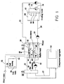
- figure 1 illustrates the apparatus comprising a tank 20 for storage of a mixture of ice particles/ice flakes, water and salt in the form of a slurry (ice slush), an ice machine 10 for production of so-called ice particles, a salt supply 30 with proportional feeder for dosing of salt to the buffer tank 20, and a treatment tub 50 for treatment of the product units.
- a tank 20 for storage of a mixture of ice particles/ice flakes, water and salt in the form of a slurry (ice slush)
- an ice machine 10 for production of so-called ice particles
- a salt supply 30 with proportional feeder for dosing of salt to the buffer tank 20
- a treatment tub 50 for treatment of the product units.
- a pipe 12 connects the ice machine 10 with the slurry tank 20, as the pipe 12 leads into the upper layer of the slurry tank 20.
- a pipe 16 for cold water leads from the bottom of the slurry tank 20 and returns to the ice machine for production of new ice.
- the ice machine is powered by an electrical aggregate 14.
- a tank 30 is arranged to be fed with salt (possibly an alcohol) and water for the creation of a salt or alcoholic water solution (such as brine).
- the salt may comprise normal cooking salt or other salt.
- the water is transported from a source not illustrated and to the tank 30 via a branch pipe 36 which derives from a main water pipe 32.
- Salt is fed to the tank 30 from a source not illustrated.
- Thermometers and salt content gauges are used to ensure that the salt water mixture (brine) has the correct salt content, in order to achieve the required freezing point reduction in the proportion of water to be mixed in the tank 20 with the ice particles or ice flakes from the ice machine 10.
- Pipe 34 can transport the salt water from the salt water tank 30 and to the ice slurry tank 20.
- the main water pipe 32 is continued for the feeding of the required volume of water directly to the tank 20. All pipes include required (not illustrated) regulation devices, shut-off valves and the like in order to produce the correct dosage.
- the purpose of the salt is to reduce the freezing point in the water.
- Salt water with up to 2 weight % salt has a freezing point of approx. -2.5°C and can be pumped as a mixture with the ice particles. An equilibrium is achieved between the salt water and the ice particles at the above-mentioned temperature, -2.5°C.
- Other chemicals than salt can be used to produce this effect, such as alcohol or other organic substances.
- the ice slurry tank 20 The ice slurry tank 20
- a pipe 22 leads from the upper layer of the slurry tank 20 and to a treatment tank 50 for supply of ice slurry to the tank 50, as a pump 54 is utilised for this supply.
- the figure illustrates that the pipe 22 transports the ice slurry into the bottom of the tank 50.
- a pipe 24 with pump/shut-off valve 23 can transport a volume of water from the bottom of the tank 50 and return it to the ice slurry tank 20. A circulation flow is thereby produced between the ice slurry tank 20 and the treatment tank 50.
- the treatment tank 50 The treatment tank 50
- a treatment tank 50 for the product units has been illustrated schematically on the right hand side of figure 1 , and in a more detailed and enlarged vertical section in figure 2 .
- a number of ejection nozzles have been assembled, three of which are illustrated - 60, 62 and 64.
- An overflow funnel 58 has been mounted at the top of the tank (a trough with a pipe 52 leading from the bottom of the funnel and connected with the three ejection nozzles 60,62,64 for ejection of ice sludge in the tank 50).
- the ice sludge ready for pumping which collects in the trough is transported by a pump 56 through the pipe 52 and to the nozzles 60,62,64 and ejected at significant force out into the tank.
- the nozzles can be set at varying angles for ejection of the ice slurry (such as horizontal or vertical ejection), or at any other angle required for individual utilisation.
- ice slurry heats up and melts
- water from the melted ice
- required temperature sensors are mounted to monitor the ice/water mixture in the tank.
- the ice sludge float upwards and create an upper layer in the tank, while the water volume remains at the bottom of the tank.
- water from the bottom of the tank is fed from the tank and back to the tank 20 via pipe 24, while a fresh portion of ice sludge is fed from the tank 20 via pipe 22.
- the collection trough 58 is positioned so that the ice/water mixture is skimmed off from the upper part of the tank.
- the actual ejection process will help provide a continuous stirring of the ice in the water.
- the ice machine 10 supplies ice to the ice slurry tank 20 .
- the ice machine has an inbuilt automatic system which controls the temperature of the ice which, together with the salt content, reflects the ice concentration. That is to say that the salt tank 30 automatically doses salt into the ice slurry, and the temperature and consistency of the ice is automatically controlled via PLS control of the ice machine.
- a viscosimeter is utilised in the slush tank which continually circulates the ice slurry, so that the viscosity count is proportional with the ice concentration in the ice slurry. In this way, the ice concentration in the ice slurry tank can be simulated.
- FIG 2 contains an illustration of a rack 70 with a frame work construction which is arranged to be placed in the tank 50.
- the rack 70 is arranged for suspension of a large number of product units 72 on the rack, the contents of which require rapid cooling (or heating).
- the product units 72 are suspended/lying or standing upright in a systematic pattern so that there is a space between each product unit 72. This space is necessary in order to pump the ice slurry in between the product units 72. This provides a good and rapid heat exchange contact between the ice slurry and the external surface of the product units 72.
- the product units are treated batch wise.
- the system creates three separate and individually functioning circuits:
- the ice slurry in the tank 20 is transported out from the upper part of the tank and fed through pipe 22 to the treatment tub 50.
- a volume of water (after the ice has melted and cooled the bags) is transported out of the tank via pipe 24, and this volume of water is fed back to the buffer tank via pipe 24.
- a paddle mechanism 40 with tilted axis of rotation and paddles 44, is operated/rotated in order to keep the suspension "homogenous" so that the mass does not separate into an upper concentrated layer of ice and a lower layer of water.
- the actual ice has a lower density than water, and will consequently float upwards and create an upper layer of ice if the mass is not stirred. Only one tank 50 is illustrated, but several adjacent tanks could be utilised in turn for treatment (submersion of racks with product units/bags).
- a volume of the cold water from the bottom of the tank 20 is fed back to the ice machine 10 via the pipe 16 for production of new ice which is then returned via the pipe 12 to the tank 20.
- a separate circuit is connected to the treatment tank 50 and is utilised to feed/control the ice slurry, via the injector nozzles 60,62,64, into the treatment tub 50 between the bags of units to be treated.
- the volume of ice particles and salt in the water in the buffer tank 20 is continuously regulated by adding salt water from the supply 30 via pipe 34, water from pipe 32 and by adding ice particles from the ice machine 10. This entire process can be automated by using suitable measurement equipment.
- the method provides significant savings on energy as:
- the ice slurry is kept in constant, homogenous movement by using a frequency-controlled paddle mechanism 40 in the ice slurry tank.
- the ice slurry tank 20 and the ice machine are normally assembled in a separate engine room.
- the ice slurry is pumped out to a cooling tub in the tank 50 .
- the cooling tubs 50 are constructed to allow for adaptation to existing equipment used in the production of hot food, for example for a so-called "sous vide" production.
- the design involves the cooling tank system with 3 separate tanks, so that these can be operated individually. That is to say that each of the three cooling tubs are adapted to special racks used to heat/cook (or sous vide treat) vacuum packed food. Vacuum bags are packaged with raw ingredients (sauces, meat, fish, vegetables, desserts, stews etc.), and these go through heat treatment in special steam ovens (combi-steamers).
- the vacuum bags are then heat treated (practically boiled) in a sous vide process (i.e. an entirely closed system), so that no nutrients, juice etc. can escape during the boiling process.
- a sous vide process i.e. an entirely closed system
- the entire rack approximately 100 vacuum bags each weighing 1.2 kg
- the tub is then filled with ice particles.
- the circulation pump 56 starts and circulates the ice slurry, almost as in a swimming pool. Ice crystals which float up to the surface of the tub are sucked into the skimmer like construction 58 on a level with the upper layer of ice slush, and then sucked through a pump and re-ejected with great force via the injector nozzles 60,62,64, through the rack and in between the vacuum bags.
- the ice slush has practically the same viscosity as water, which allows the ice to be pumped just as easily as water. In other words, the maximum amount of energy can be produced exactly when required.
- Temperature sensors 80 mounted in the various height layers in the water send signals to the control system for the process, which activates pumps and the ice slurry tank 20 in the engine room, that if the water temperature in the tank 50 exceeds e.g. +1°C, a specified volume of melted water from the tub is fed back via pipe 24 to the large ice slurry tan, and more ice slurry in the tub 20 is transported via pipe 22 and to the treatment tank 50. This allows for control and monitoring of the temperature in the ice slurry in the tub where the warm vacuum bags have been submerged for cooling.
- a method has been presented where the refrigeration process forms a part of a logistic process within a commercial kitchen which produces, packages, heat treats, cools and distributes vacuum packed foot to smaller satellite kitchens.
- a cooling tub has been developed which exploits the qualities of ice slurry in a purely mechanical manner, in that the method utilises pumps, injectors, temperature control and the geometric shape of the tub to circulate the ice crystals in the above-mentioned salt brine around the hot vacuum bags.
- the ice which together with a salt brine of approx. 2%, can be produced by a special flake ice machine, is mixed with fresh water, so that the ice slurry at the required consistency consists of approximately 25% ice crystals, 2% NaCl (cooking salt) and the rest fresh water.
- a saline solution is utilised allows for the water temperature in the actual ice slurry to be reduced to approx. -2°C without the water freezing. This is an ideal temperature which prevents the vacuum bags freezing "at the edges" - a common problem in the freezing tunnels (blast chillers) where a low air temperature is required to achieve the core temperature rapidly.
- the ice produced is supplied by the ice machine 30 to the ice slurry tank 20 and is controlled by the control system for the process.
- the ice slurry would not have the capacity to exploit the enthalpy of the ice if the ice lay still and was allowed to melt around the warm products it is meant to cool.
- the ice would then melt around the warm product and would create an insulating layer, so that the "cold" energy in the ice crystals (enthalpy) does not achieve a sufficient function on contact with the product bags.
- the whole point is to keep the ice crystals in movement so that these achieve heat exchange with the warm packaged product. If the ice crystals do not circulate continuously around the entire tub, the ice crystal energy in relation to the water's energy will not achieve a satisfactory functional level. This is a significant feature which has been resolved with the present invention.
- the method and apparatus according to the invention can be applied to other functions, such as a cooling module (a similar tub adapted to a packaging line e.g. in a so-called “dyptrekker” system where heat filling equipment is utilised), possibly with an inbuilt conveyor system within the tub.
- a cooling module a similar tub adapted to a packaging line e.g. in a so-called "dyptrekker” system where heat filling equipment is utilised
- an inbuilt conveyor system within the tub.
- Another application could be an ice slurry plant directly adapted to e.g. a cooking pot (a steam boiler) or sous vide tank or autoclave or so-called “dyptrekker” system in a commercial kitchen or food manufacturer, so that the ice slurry plant is automatically connected (interfaced) within the cook-chill process; and possibly controlled by the same instrumentation which operates the hot food production equipment.
- the ice slush would automatically or manually be pumped into these machines in an "in-line" logistics process.
Landscapes
- Engineering & Computer Science (AREA)
- Chemical & Material Sciences (AREA)
- Life Sciences & Earth Sciences (AREA)
- Physics & Mathematics (AREA)
- Thermal Sciences (AREA)
- Combustion & Propulsion (AREA)
- General Engineering & Computer Science (AREA)
- Mechanical Engineering (AREA)
- Food Science & Technology (AREA)
- Polymers & Plastics (AREA)
- Zoology (AREA)
- Wood Science & Technology (AREA)
- Chemical Kinetics & Catalysis (AREA)
- Materials Engineering (AREA)
- Organic Chemistry (AREA)
- Freezing, Cooling And Drying Of Foods (AREA)
- Heat Treatment Of Articles (AREA)
- Devices That Are Associated With Refrigeration Equipment (AREA)
- Physical Or Chemical Processes And Apparatus (AREA)
- Thermotherapy And Cooling Therapy Devices (AREA)
- Manufacture, Treatment Of Glass Fibers (AREA)
- Lubricants (AREA)
Applications Claiming Priority (2)
| Application Number | Priority Date | Filing Date | Title |
|---|---|---|---|
| NO20031711A NO320987B1 (no) | 2003-04-14 | 2003-04-14 | Fremgangsmåte og system til temperering,særlig avkjøling, av produktenheter, samt anvendelse derav |
| PCT/NO2003/000254 WO2004090443A1 (en) | 2003-04-14 | 2003-07-23 | Method and system for tempering of product units in a tank, and application thereof |
Publications (2)
| Publication Number | Publication Date |
|---|---|
| EP1639302A1 EP1639302A1 (en) | 2006-03-29 |
| EP1639302B1 true EP1639302B1 (en) | 2009-11-25 |
Family
ID=19914673
Family Applications (1)
| Application Number | Title | Priority Date | Filing Date |
|---|---|---|---|
| EP20030816620 Expired - Lifetime EP1639302B1 (en) | 2003-04-14 | 2003-07-23 | Method and system for tempering of product units in a tank, and application thereof |
Country Status (12)
| Country | Link |
|---|---|
| US (1) | US9151533B2 (da) |
| EP (1) | EP1639302B1 (da) |
| JP (1) | JP4249137B2 (da) |
| KR (1) | KR20050122255A (da) |
| CN (1) | CN1771418B (da) |
| AT (1) | ATE449941T1 (da) |
| AU (1) | AU2003263672A1 (da) |
| CA (1) | CA2563170C (da) |
| DE (1) | DE60330278D1 (da) |
| DK (1) | DK1639302T3 (da) |
| NO (2) | NO320987B1 (da) |
| WO (1) | WO2004090443A1 (da) |
Families Citing this family (31)
| Publication number | Priority date | Publication date | Assignee | Title |
|---|---|---|---|---|
| CA2562722C (en) * | 2006-09-12 | 2015-11-24 | Sunwell Engineering Company Limited | Method and apparatus for cooling product |
| GB0619319D0 (en) * | 2006-09-30 | 2006-11-08 | Pickup Gary | Food processing apparatus and method |
| GB2441836B (en) * | 2007-03-16 | 2008-08-13 | Brewfitt Ltd | Drinks dispensing apparatus |
| DE102010018497A1 (de) * | 2010-04-22 | 2011-10-27 | Hochschule Karlsruhe-Technik Und Wirtschaft | Verfahren und Vorrichtung zur Erzeugung von Eisbrei |
| CN101922830B (zh) * | 2010-08-05 | 2011-08-24 | 华中科技大学 | 一种过冷液体冰浆连续制取装置 |
| US9839230B2 (en) * | 2011-03-31 | 2017-12-12 | Raymond L. Neff | Device for defrosting, warming and cooking using a circulating fluid |
| US9310140B2 (en) | 2012-02-07 | 2016-04-12 | Rebound Technologies, Inc. | Methods, systems, and devices for thermal enhancement |
| US9587873B2 (en) * | 2012-03-27 | 2017-03-07 | Global Cooling, Inc. | Energy efficient biological freezer with vial management system |
| US9845988B2 (en) | 2014-02-18 | 2017-12-19 | Supercooler Technologies, Inc. | Rapid spinning liquid immersion beverage supercooler |
| US9631856B2 (en) * | 2013-01-28 | 2017-04-25 | Supercooler Technologies, Inc. | Ice-accelerator aqueous solution |
| US9927162B2 (en) * | 2013-04-22 | 2018-03-27 | Leslie A Field | Generation and deployment of ice with modified optical and/or thermal properties |
| CN103591746B (zh) * | 2013-10-16 | 2015-09-16 | 钱志刚 | 盐溶解式温度调节装置及使用方法 |
| US10302354B2 (en) | 2013-10-28 | 2019-05-28 | Supercooler Technologies, Inc. | Precision supercooling refrigeration device |
| US10149487B2 (en) | 2014-02-18 | 2018-12-11 | Supercooler Technologies, Inc. | Supercooled beverage crystallization slush device with illumination |
| WO2016041608A1 (en) * | 2014-09-19 | 2016-03-24 | Bitzer Kuehlmaschinenbau Gmbh | Storage unit and tempering system for a storage unit |
| US10995993B2 (en) | 2014-09-27 | 2021-05-04 | Rebound Technologies, Inc. | Thermal recuperation methods, systems, and devices |
| USD778687S1 (en) | 2015-05-28 | 2017-02-14 | Supercooler Technologies, Inc. | Supercooled beverage crystallization slush device with illumination |
| JP6488024B2 (ja) * | 2015-11-19 | 2019-03-20 | ブランテック株式会社 | 保冷庫、移動体、氷スラリー供給システム、被保冷品輸送システム、被保冷品の保冷方法、被保冷品の輸送方法 |
| US10584904B2 (en) | 2017-03-27 | 2020-03-10 | Rebound Technologies, Inc. | Cycle enhancement methods, systems, and devices |
| US11353254B2 (en) * | 2017-05-18 | 2022-06-07 | Blanctec Co., Ltd. | State change control device and state change control method |
| WO2019165328A1 (en) | 2018-02-23 | 2019-08-29 | Rebound Technologies, Inc. | Freeze point suppression cycle control systems, methods, and devices |
| US20200033041A1 (en) * | 2018-07-25 | 2020-01-30 | James Chun Koh | Apparatus for making fine ice with salinity |
| WO2020132467A1 (en) | 2018-12-20 | 2020-06-25 | Rebound Technologies, Inc. | Thermo-chemical recuperation systems, devices, and methods |
| CN110094909B (zh) * | 2019-05-16 | 2021-02-05 | 广东海洋大学 | 一种用于食品速冻加工的超高压冷却食品瞬冻装置 |
| CN111288699B (zh) * | 2020-02-25 | 2021-11-19 | 中国航发沈阳发动机研究所 | 一种航空发动机整机吞冰试验用冰片的制备装置及方法 |
| KR102272050B1 (ko) * | 2020-12-24 | 2021-07-01 | 변종수 | 슬러리 아이스를 이용한 저온 숙성 장치 및 방법 |
| CN113970222B (zh) * | 2021-09-30 | 2022-07-22 | 浙江工业大学 | 一种远洋渔获物分级预冷装置及其应用 |
| CN115325753B (zh) * | 2022-03-25 | 2023-05-16 | 北京航天试验技术研究所 | 一种基于氦循环的双预冷低温浆体制备装置及其方法 |
| KR102815358B1 (ko) * | 2023-01-30 | 2025-06-05 | 삼성물산 주식회사 | 침지 냉각 방식의 유량 제어장치 및 그 방법 |
| KR102731334B1 (ko) * | 2023-08-21 | 2024-11-18 | 주식회사 이스턴웰스 | 슬러리 급속동결수조가 설치되는 원물 냉각 방법 |
| KR102717333B1 (ko) * | 2023-08-21 | 2024-10-15 | 주식회사 이스턴웰스 | 슬러리 급속동결수조가 설치되는 원물 냉각 시스템 |
Family Cites Families (21)
| Publication number | Priority date | Publication date | Assignee | Title |
|---|---|---|---|---|
| US3097501A (en) * | 1963-07-16 | pappas | ||
| US1547258A (en) * | 1923-02-21 | 1925-07-28 | John W Newton | Single-tank comestible brine freezer |
| US2263452A (en) * | 1941-03-28 | 1941-11-18 | Mechanical Res Inc | Process and apparatus for freezing food products |
| US3300993A (en) * | 1964-02-25 | 1967-01-31 | Alfred H Schlemmer | Freezing apparatus and method |
| GB1520737A (en) * | 1974-07-22 | 1978-08-09 | Doust D J | Continuously operable brine freezing system for freezing fish |
| GB1481537A (en) * | 1974-08-19 | 1977-08-03 | Doust D | Apparatus and method of freezing fish on board a fishing vessel |
| US4249388A (en) * | 1980-01-30 | 1981-02-10 | Demco, Inc. | Automatic liquid ice system |
| FR2544179A1 (fr) * | 1983-04-15 | 1984-10-19 | Lasserre Andre | Procede de cuisson pasteurisation de produits alimentaires dans leurs emballages sous vide d'air realise a l'aide d'une machine combinant cuisson et refroidissement |
| US4484448A (en) * | 1983-07-25 | 1984-11-27 | Growers Ice Company | Liquid ice injection system |
| FR2562217B1 (fr) * | 1984-03-29 | 1987-02-06 | Morel Albert | Appareil de refroidissement pour produits alimentaires |
| US4912935A (en) * | 1987-09-17 | 1990-04-03 | Sunwell Engineering Company Ltd. | Ice storage and distribution unit |
| JP2617126B2 (ja) * | 1987-07-20 | 1997-06-04 | サンウエル エンジニアリング カンパニー リミテッド | 船上の魚を冷却する方法および装置 |
| US5168712A (en) * | 1990-03-19 | 1992-12-08 | Instacool Inc. Of North America | Rapid cooling through a thin flexible membrane |
| JPH0728710B2 (ja) * | 1990-09-10 | 1995-04-05 | 株式会社テクニカン | 食品冷凍法およびその冷凍装置 |
| NO923173L (no) * | 1992-08-13 | 1994-02-14 | Mmc As | Anordning ved isfremstilling |
| CA2143465C (en) * | 1995-02-27 | 2007-05-22 | Vladimir Goldstein | Ice slurry delivery system |
| US5761913A (en) * | 1996-10-24 | 1998-06-09 | Winterlab Limited | Ribbon-freezing method and apparatus |
| DK173153B1 (da) * | 1997-10-28 | 2000-02-14 | Slagteriernes Forskningsinst | Fremgangsmåde og system til nedkøling af slagtevarme svineslagtekroppe |
| US6116043A (en) * | 1997-12-12 | 2000-09-12 | Delaware Capital Formation Inc. | Food processing apparatus |
| US6216469B1 (en) * | 1998-06-15 | 2001-04-17 | Bruce Miller | Device and process for chilling goods |
| ATE288061T1 (de) * | 2001-03-27 | 2005-02-15 | Skaginn Hf | Verfahren und vorrichtung zur herstellung von flüssigeis |
-
2003
- 2003-04-14 NO NO20031711A patent/NO320987B1/no not_active IP Right Cessation
- 2003-07-23 JP JP2004570589A patent/JP4249137B2/ja not_active Expired - Fee Related
- 2003-07-23 EP EP20030816620 patent/EP1639302B1/en not_active Expired - Lifetime
- 2003-07-23 AT AT03816620T patent/ATE449941T1/de not_active IP Right Cessation
- 2003-07-23 US US10/552,986 patent/US9151533B2/en active Active
- 2003-07-23 AU AU2003263672A patent/AU2003263672A1/en not_active Abandoned
- 2003-07-23 KR KR1020057019405A patent/KR20050122255A/ko not_active Ceased
- 2003-07-23 WO PCT/NO2003/000254 patent/WO2004090443A1/en not_active Ceased
- 2003-07-23 CN CN038264765A patent/CN1771418B/zh not_active Expired - Fee Related
- 2003-07-23 DK DK03816620T patent/DK1639302T3/da active
- 2003-07-23 DE DE60330278T patent/DE60330278D1/de not_active Expired - Lifetime
- 2003-07-23 CA CA 2563170 patent/CA2563170C/en not_active Expired - Fee Related
-
2005
- 2005-11-11 NO NO20055344A patent/NO20055344L/no not_active Application Discontinuation
Also Published As
| Publication number | Publication date |
|---|---|
| ATE449941T1 (de) | 2009-12-15 |
| AU2003263672A1 (en) | 2004-11-01 |
| CA2563170C (en) | 2011-10-04 |
| NO20055344L (no) | 2006-01-09 |
| CN1771418B (zh) | 2010-05-26 |
| NO20055344D0 (no) | 2005-11-11 |
| DE60330278D1 (de) | 2010-01-07 |
| US9151533B2 (en) | 2015-10-06 |
| KR20050122255A (ko) | 2005-12-28 |
| NO320987B1 (no) | 2006-02-20 |
| CN1771418A (zh) | 2006-05-10 |
| EP1639302A1 (en) | 2006-03-29 |
| DK1639302T3 (da) | 2010-04-12 |
| NO20031711L (no) | 2004-10-15 |
| NO20031711D0 (no) | 2003-04-14 |
| US20070137223A1 (en) | 2007-06-21 |
| CA2563170A1 (en) | 2004-10-21 |
| WO2004090443A1 (en) | 2004-10-21 |
| JP2006514256A (ja) | 2006-04-27 |
| JP4249137B2 (ja) | 2009-04-02 |
Similar Documents
| Publication | Publication Date | Title |
|---|---|---|
| CA2563170C (en) | Method and system for tempering of product units in a tank, and application thereof | |
| US10149486B2 (en) | Apparatus for thawing or cooling food products | |
| US4551159A (en) | Ice making machine and method | |
| JP2006514256A5 (da) | ||
| CN101160062B (zh) | 源自捕鱼和屠宰业的原料用的水解处理及其所用的池 | |
| US7603868B2 (en) | Method and apparatus for producing fluid ice | |
| US20220192235A1 (en) | Food freezing device, food freezing method and frozen food | |
| WO2009082679A1 (en) | Grain hydration and flaking process, apparatus, and product | |
| AU659511B2 (en) | Apparatus for effecting heat exchange between a liquid and a particulate material | |
| JP2019207046A (ja) | 氷スラリー製造装置及び冷凍システム | |
| KR102105087B1 (ko) | 감자탕 제조 장치 및 방법 | |
| CN216255369U (zh) | 一种连续卤煮装置 | |
| JP2019205366A (ja) | 冷凍装置及び冷凍システム | |
| WO2004081469A1 (en) | A method and apparatus for producing homogenous fluid ice | |
| WO2022184689A1 (en) | Arrangement for freezing and thawing seafood | |
| CN114403369A (zh) | 一种冰浸法肌红蛋白、骨红蛋白双浸出改善肉质制备工艺 | |
| EP3945834A1 (en) | Temperature management and reuse of food processing liquid | |
| CN206064233U (zh) | 一体式液体温度、盐度含量率控制器 | |
| US3291612A (en) | Method for collecting and preserving blood | |
| CN120335522A (zh) | 料理机的控制方法及料理机 | |
| RU2438342C2 (ru) | Установка для изготовления так называемого мягкого мороженого и способ подачи соответствующей смеси | |
| JP2000266435A (ja) | 生鮮食料品の貯蔵装置 | |
| Goyette et al. | An improved continuous liquid-icing system based on submerged mixing of water and ice | |
| JP2006003038A (ja) | 氷構造体、塩分を含む氷の製造方法及び製造装置 | |
| CN106378031A (zh) | 一体式液体温度、盐度含量率控制器 |
Legal Events
| Date | Code | Title | Description |
|---|---|---|---|
| PUAI | Public reference made under article 153(3) epc to a published international application that has entered the european phase |
Free format text: ORIGINAL CODE: 0009012 |
|
| 17P | Request for examination filed |
Effective date: 20051114 |
|
| AK | Designated contracting states |
Kind code of ref document: A1 Designated state(s): AT BE BG CH CY CZ DE DK EE ES FI FR GB GR HU IE IT LI LU MC NL PT RO SE SI SK TR |
|
| AX | Request for extension of the european patent |
Extension state: AL LT LV MK |
|
| 17Q | First examination report despatched |
Effective date: 20070328 |
|
| GRAP | Despatch of communication of intention to grant a patent |
Free format text: ORIGINAL CODE: EPIDOSNIGR1 |
|
| GRAS | Grant fee paid |
Free format text: ORIGINAL CODE: EPIDOSNIGR3 |
|
| GRAA | (expected) grant |
Free format text: ORIGINAL CODE: 0009210 |
|
| AK | Designated contracting states |
Kind code of ref document: B1 Designated state(s): AT BE BG CH CY CZ DE DK EE ES FI FR GB GR HU IE IT LI LU MC NL PT RO SE SI SK TR |
|
| AX | Request for extension of the european patent |
Extension state: AL LT LV MK |
|
| REG | Reference to a national code |
Ref country code: GB Ref legal event code: FG4D |
|
| REG | Reference to a national code |
Ref country code: CH Ref legal event code: EP |
|
| REG | Reference to a national code |
Ref country code: IE Ref legal event code: FG4D |
|
| REF | Corresponds to: |
Ref document number: 60330278 Country of ref document: DE Date of ref document: 20100107 Kind code of ref document: P |
|
| REG | Reference to a national code |
Ref country code: SE Ref legal event code: TRGR |
|
| REG | Reference to a national code |
Ref country code: NL Ref legal event code: T3 |
|
| REG | Reference to a national code |
Ref country code: CH Ref legal event code: NV Representative=s name: ARNOLD & SIEDSMA AG |
|
| REG | Reference to a national code |
Ref country code: DK Ref legal event code: T3 |
|
| LTIE | Lt: invalidation of european patent or patent extension |
Effective date: 20091125 |
|
| PG25 | Lapsed in a contracting state [announced via postgrant information from national office to epo] |
Ref country code: PT Free format text: LAPSE BECAUSE OF FAILURE TO SUBMIT A TRANSLATION OF THE DESCRIPTION OR TO PAY THE FEE WITHIN THE PRESCRIBED TIME-LIMIT Effective date: 20100325 Ref country code: FI Free format text: LAPSE BECAUSE OF FAILURE TO SUBMIT A TRANSLATION OF THE DESCRIPTION OR TO PAY THE FEE WITHIN THE PRESCRIBED TIME-LIMIT Effective date: 20091125 |
|
| PG25 | Lapsed in a contracting state [announced via postgrant information from national office to epo] |
Ref country code: SI Free format text: LAPSE BECAUSE OF FAILURE TO SUBMIT A TRANSLATION OF THE DESCRIPTION OR TO PAY THE FEE WITHIN THE PRESCRIBED TIME-LIMIT Effective date: 20091125 Ref country code: CY Free format text: LAPSE BECAUSE OF FAILURE TO SUBMIT A TRANSLATION OF THE DESCRIPTION OR TO PAY THE FEE WITHIN THE PRESCRIBED TIME-LIMIT Effective date: 20091125 |
|
| PG25 | Lapsed in a contracting state [announced via postgrant information from national office to epo] |
Ref country code: AT Free format text: LAPSE BECAUSE OF FAILURE TO SUBMIT A TRANSLATION OF THE DESCRIPTION OR TO PAY THE FEE WITHIN THE PRESCRIBED TIME-LIMIT Effective date: 20091125 Ref country code: BE Free format text: LAPSE BECAUSE OF FAILURE TO SUBMIT A TRANSLATION OF THE DESCRIPTION OR TO PAY THE FEE WITHIN THE PRESCRIBED TIME-LIMIT Effective date: 20091125 |
|
| PG25 | Lapsed in a contracting state [announced via postgrant information from national office to epo] |
Ref country code: RO Free format text: LAPSE BECAUSE OF FAILURE TO SUBMIT A TRANSLATION OF THE DESCRIPTION OR TO PAY THE FEE WITHIN THE PRESCRIBED TIME-LIMIT Effective date: 20091125 Ref country code: ES Free format text: LAPSE BECAUSE OF FAILURE TO SUBMIT A TRANSLATION OF THE DESCRIPTION OR TO PAY THE FEE WITHIN THE PRESCRIBED TIME-LIMIT Effective date: 20100308 Ref country code: EE Free format text: LAPSE BECAUSE OF FAILURE TO SUBMIT A TRANSLATION OF THE DESCRIPTION OR TO PAY THE FEE WITHIN THE PRESCRIBED TIME-LIMIT Effective date: 20091125 Ref country code: BG Free format text: LAPSE BECAUSE OF FAILURE TO SUBMIT A TRANSLATION OF THE DESCRIPTION OR TO PAY THE FEE WITHIN THE PRESCRIBED TIME-LIMIT Effective date: 20100225 |
|
| PG25 | Lapsed in a contracting state [announced via postgrant information from national office to epo] |
Ref country code: SK Free format text: LAPSE BECAUSE OF FAILURE TO SUBMIT A TRANSLATION OF THE DESCRIPTION OR TO PAY THE FEE WITHIN THE PRESCRIBED TIME-LIMIT Effective date: 20091125 Ref country code: CZ Free format text: LAPSE BECAUSE OF FAILURE TO SUBMIT A TRANSLATION OF THE DESCRIPTION OR TO PAY THE FEE WITHIN THE PRESCRIBED TIME-LIMIT Effective date: 20091125 |
|
| PLBE | No opposition filed within time limit |
Free format text: ORIGINAL CODE: 0009261 |
|
| STAA | Information on the status of an ep patent application or granted ep patent |
Free format text: STATUS: NO OPPOSITION FILED WITHIN TIME LIMIT |
|
| PG25 | Lapsed in a contracting state [announced via postgrant information from national office to epo] |
Ref country code: GR Free format text: LAPSE BECAUSE OF FAILURE TO SUBMIT A TRANSLATION OF THE DESCRIPTION OR TO PAY THE FEE WITHIN THE PRESCRIBED TIME-LIMIT Effective date: 20100226 |
|
| 26N | No opposition filed |
Effective date: 20100826 |
|
| PG25 | Lapsed in a contracting state [announced via postgrant information from national office to epo] |
Ref country code: MC Free format text: LAPSE BECAUSE OF NON-PAYMENT OF DUE FEES Effective date: 20100731 |
|
| PG25 | Lapsed in a contracting state [announced via postgrant information from national office to epo] |
Ref country code: IT Free format text: LAPSE BECAUSE OF FAILURE TO SUBMIT A TRANSLATION OF THE DESCRIPTION OR TO PAY THE FEE WITHIN THE PRESCRIBED TIME-LIMIT Effective date: 20091125 |
|
| PG25 | Lapsed in a contracting state [announced via postgrant information from national office to epo] |
Ref country code: IE Free format text: LAPSE BECAUSE OF NON-PAYMENT OF DUE FEES Effective date: 20100723 |
|
| PGFP | Annual fee paid to national office [announced via postgrant information from national office to epo] |
Ref country code: DK Payment date: 20110801 Year of fee payment: 9 Ref country code: CH Payment date: 20110804 Year of fee payment: 9 |
|
| PG25 | Lapsed in a contracting state [announced via postgrant information from national office to epo] |
Ref country code: HU Free format text: LAPSE BECAUSE OF FAILURE TO SUBMIT A TRANSLATION OF THE DESCRIPTION OR TO PAY THE FEE WITHIN THE PRESCRIBED TIME-LIMIT Effective date: 20100526 Ref country code: LU Free format text: LAPSE BECAUSE OF NON-PAYMENT OF DUE FEES Effective date: 20100723 |
|
| PG25 | Lapsed in a contracting state [announced via postgrant information from national office to epo] |
Ref country code: TR Free format text: LAPSE BECAUSE OF FAILURE TO SUBMIT A TRANSLATION OF THE DESCRIPTION OR TO PAY THE FEE WITHIN THE PRESCRIBED TIME-LIMIT Effective date: 20091125 |
|
| PGFP | Annual fee paid to national office [announced via postgrant information from national office to epo] |
Ref country code: SE Payment date: 20120724 Year of fee payment: 10 Ref country code: GB Payment date: 20120724 Year of fee payment: 10 |
|
| PGFP | Annual fee paid to national office [announced via postgrant information from national office to epo] |
Ref country code: FR Payment date: 20120816 Year of fee payment: 10 |
|
| PGFP | Annual fee paid to national office [announced via postgrant information from national office to epo] |
Ref country code: NL Payment date: 20120725 Year of fee payment: 10 |
|
| REG | Reference to a national code |
Ref country code: NL Ref legal event code: V1 Effective date: 20140201 |
|
| REG | Reference to a national code |
Ref country code: DK Ref legal event code: EBP Effective date: 20130731 |
|
| REG | Reference to a national code |
Ref country code: CH Ref legal event code: PL |
|
| REG | Reference to a national code |
Ref country code: SE Ref legal event code: EUG |
|
| GBPC | Gb: european patent ceased through non-payment of renewal fee |
Effective date: 20130723 |
|
| REG | Reference to a national code |
Ref country code: FR Ref legal event code: ST Effective date: 20140331 |
|
| PG25 | Lapsed in a contracting state [announced via postgrant information from national office to epo] |
Ref country code: LI Free format text: LAPSE BECAUSE OF NON-PAYMENT OF DUE FEES Effective date: 20130731 Ref country code: CH Free format text: LAPSE BECAUSE OF NON-PAYMENT OF DUE FEES Effective date: 20130731 Ref country code: SE Free format text: LAPSE BECAUSE OF NON-PAYMENT OF DUE FEES Effective date: 20130724 Ref country code: GB Free format text: LAPSE BECAUSE OF NON-PAYMENT OF DUE FEES Effective date: 20130723 Ref country code: NL Free format text: LAPSE BECAUSE OF NON-PAYMENT OF DUE FEES Effective date: 20140201 |
|
| PGFP | Annual fee paid to national office [announced via postgrant information from national office to epo] |
Ref country code: DE Payment date: 20140107 Year of fee payment: 11 |
|
| PG25 | Lapsed in a contracting state [announced via postgrant information from national office to epo] |
Ref country code: FR Free format text: LAPSE BECAUSE OF NON-PAYMENT OF DUE FEES Effective date: 20130731 |
|
| PG25 | Lapsed in a contracting state [announced via postgrant information from national office to epo] |
Ref country code: DK Free format text: LAPSE BECAUSE OF NON-PAYMENT OF DUE FEES Effective date: 20130731 |
|
| REG | Reference to a national code |
Ref country code: DE Ref legal event code: R119 Ref document number: 60330278 Country of ref document: DE |
|
| PG25 | Lapsed in a contracting state [announced via postgrant information from national office to epo] |
Ref country code: DE Free format text: LAPSE BECAUSE OF NON-PAYMENT OF DUE FEES Effective date: 20150203 |
|
| REG | Reference to a national code |
Ref country code: DE Ref legal event code: R119 Ref document number: 60330278 Country of ref document: DE Effective date: 20150203 |