EP1639921B1 - Elektrischer Wasserkocher - Google Patents
Elektrischer Wasserkocher Download PDFInfo
- Publication number
- EP1639921B1 EP1639921B1 EP05255987A EP05255987A EP1639921B1 EP 1639921 B1 EP1639921 B1 EP 1639921B1 EP 05255987 A EP05255987 A EP 05255987A EP 05255987 A EP05255987 A EP 05255987A EP 1639921 B1 EP1639921 B1 EP 1639921B1
- Authority
- EP
- European Patent Office
- Prior art keywords
- appliance
- channel
- heat bridge
- actuator
- sensor
- Prior art date
- Legal status (The legal status is an assumption and is not a legal conclusion. Google has not performed a legal analysis and makes no representation as to the accuracy of the status listed.)
- Revoked
Links
- 238000009835 boiling Methods 0.000 title claims abstract description 27
- 239000007788 liquid Substances 0.000 title claims abstract description 22
- 238000010438 heat treatment Methods 0.000 claims abstract description 32
- 238000001816 cooling Methods 0.000 claims abstract description 17
- 239000000463 material Substances 0.000 claims description 5
- 238000012546 transfer Methods 0.000 claims description 5
- RYGMFSIKBFXOCR-UHFFFAOYSA-N Copper Chemical compound [Cu] RYGMFSIKBFXOCR-UHFFFAOYSA-N 0.000 claims description 3
- 239000010949 copper Substances 0.000 claims description 3
- 229910052802 copper Inorganic materials 0.000 claims description 3
- 239000004411 aluminium Substances 0.000 claims description 2
- XAGFODPZIPBFFR-UHFFFAOYSA-N aluminium Chemical compound [Al] XAGFODPZIPBFFR-UHFFFAOYSA-N 0.000 claims description 2
- 229910052782 aluminium Inorganic materials 0.000 claims description 2
- 230000015572 biosynthetic process Effects 0.000 claims description 2
- XLYOFNOQVPJJNP-UHFFFAOYSA-N water Substances O XLYOFNOQVPJJNP-UHFFFAOYSA-N 0.000 description 32
- 239000003570 air Substances 0.000 description 5
- 239000012080 ambient air Substances 0.000 description 5
- 230000000694 effects Effects 0.000 description 4
- 230000002093 peripheral effect Effects 0.000 description 4
- 238000005485 electric heating Methods 0.000 description 3
- 229910001220 stainless steel Inorganic materials 0.000 description 3
- 239000010935 stainless steel Substances 0.000 description 3
- 238000009792 diffusion process Methods 0.000 description 2
- 238000000034 method Methods 0.000 description 2
- 238000013459 approach Methods 0.000 description 1
- 230000009286 beneficial effect Effects 0.000 description 1
- 238000004891 communication Methods 0.000 description 1
- 239000004020 conductor Substances 0.000 description 1
- 238000010276 construction Methods 0.000 description 1
- 238000013461 design Methods 0.000 description 1
- 238000001514 detection method Methods 0.000 description 1
- 239000012530 fluid Substances 0.000 description 1
- 239000011521 glass Substances 0.000 description 1
- 210000003141 lower extremity Anatomy 0.000 description 1
- 238000004519 manufacturing process Methods 0.000 description 1
- 229920003023 plastic Polymers 0.000 description 1
- 239000004033 plastic Substances 0.000 description 1
- 230000002028 premature Effects 0.000 description 1
- 238000003825 pressing Methods 0.000 description 1
- 238000012360 testing method Methods 0.000 description 1
Images


Classifications
-
- A—HUMAN NECESSITIES
- A47—FURNITURE; DOMESTIC ARTICLES OR APPLIANCES; COFFEE MILLS; SPICE MILLS; SUCTION CLEANERS IN GENERAL
- A47J—KITCHEN EQUIPMENT; COFFEE MILLS; SPICE MILLS; APPARATUS FOR MAKING BEVERAGES
- A47J27/00—Cooking-vessels
- A47J27/21—Water-boiling vessels, e.g. kettles
- A47J27/21008—Water-boiling vessels, e.g. kettles electrically heated
- A47J27/21041—Water-boiling vessels, e.g. kettles electrically heated with heating elements arranged outside the water vessel
-
- A—HUMAN NECESSITIES
- A47—FURNITURE; DOMESTIC ARTICLES OR APPLIANCES; COFFEE MILLS; SPICE MILLS; SUCTION CLEANERS IN GENERAL
- A47J—KITCHEN EQUIPMENT; COFFEE MILLS; SPICE MILLS; APPARATUS FOR MAKING BEVERAGES
- A47J27/00—Cooking-vessels
- A47J27/21—Water-boiling vessels, e.g. kettles
- A47J27/21008—Water-boiling vessels, e.g. kettles electrically heated
- A47J27/21058—Control devices to avoid overheating, i.e. "dry" boiling, or to detect boiling of the water
- A47J27/21066—Details concerning the mounting thereof in or on the water boiling vessel
-
- A—HUMAN NECESSITIES
- A47—FURNITURE; DOMESTIC ARTICLES OR APPLIANCES; COFFEE MILLS; SPICE MILLS; SUCTION CLEANERS IN GENERAL
- A47J—KITCHEN EQUIPMENT; COFFEE MILLS; SPICE MILLS; APPARATUS FOR MAKING BEVERAGES
- A47J27/00—Cooking-vessels
- A47J27/21—Water-boiling vessels, e.g. kettles
- A47J27/21008—Water-boiling vessels, e.g. kettles electrically heated
- A47J27/21058—Control devices to avoid overheating, i.e. "dry" boiling, or to detect boiling of the water
- A47J27/21066—Details concerning the mounting thereof in or on the water boiling vessel
- A47J27/21075—Details concerning the mounting thereof in or on the water boiling vessel relating to the boiling sensor or to the channels conducting the steam thereto
-
- H—ELECTRICITY
- H05—ELECTRIC TECHNIQUES NOT OTHERWISE PROVIDED FOR
- H05B—ELECTRIC HEATING; ELECTRIC LIGHT SOURCES NOT OTHERWISE PROVIDED FOR; CIRCUIT ARRANGEMENTS FOR ELECTRIC LIGHT SOURCES, IN GENERAL
- H05B3/00—Ohmic-resistance heating
- H05B3/78—Heating arrangements specially adapted for immersion heating
- H05B3/82—Fixedly-mounted immersion heaters
-
- A—HUMAN NECESSITIES
- A47—FURNITURE; DOMESTIC ARTICLES OR APPLIANCES; COFFEE MILLS; SPICE MILLS; SUCTION CLEANERS IN GENERAL
- A47J—KITCHEN EQUIPMENT; COFFEE MILLS; SPICE MILLS; APPARATUS FOR MAKING BEVERAGES
- A47J27/00—Cooking-vessels
- A47J27/21—Water-boiling vessels, e.g. kettles
- A47J27/21008—Water-boiling vessels, e.g. kettles electrically heated
- A47J27/21058—Control devices to avoid overheating, i.e. "dry" boiling, or to detect boiling of the water
- A47J27/21108—Control devices to avoid overheating, i.e. "dry" boiling, or to detect boiling of the water using a bimetallic element
- A47J27/21125—Control devices to avoid overheating, i.e. "dry" boiling, or to detect boiling of the water using a bimetallic element the bimetallic element being a snapping disc
Definitions
- the present invention relates to liquid boiling appliances, in particular water boiling appliances such as kettles and hot water jugs, and having electric heating means provided on the base of the liquid heating chamber of the appliance.
- the heating means may, for example, comprise a sheathed electric heating element bonded to the underside of the chamber base, for example through a thermal diffusion member, or a thick film element printed onto or attached to the base of the chamber.
- Such appliances are well known in the art, and are described, for example, in WO 96/18331.
- water boiling appliances comprise a steam sensitive switch which switches off or reduces the power of the appliance heater when water in the appliance boils.
- Such controls typically comprise a temperature sensitive actuator, such as a bimetallic actuator, which is suitably arranged in fluid communication with the heating chamber. When water in the chamber boils, the steam generated is brought into contact with the actuator which then operates a control.
- the ambient temperature in the region of the sump will be hot, and not facilitate a quick reset time for the actuator after it has operated. This means that it may be difficult to reboil water quickly after the boiling control has operated as the actuator will not have reset.
- the sumps which have been proposed have taken the form of a cup which is suitably formed in or attached to the chamber base. This imposes certain design and manufacturing constraints on the designer.
- the present invention seeks to overcome or ameliorate these problems and provides an electric liquid boiling appliance, said appliance having a liquid heating chamber having a heated base, said base being provided with a sump recess for holding liquid and a thermal sensor mounted in thermal contact with a wall of said recess for determining the presence of boiling liquid in the recess; wherein said thermal sensor is received in a pocket in a heat bridge arrangement which is at least partially enclosed so as to restrict airflow over the sensor.
- the efficiency of convective heat transfer processes is enhanced by at least partially enclosing the thermal sensor.
- the small pocket of air enclosed may be rapidly heated, so that on both sides the thermal sensor, e.g. a bimetallic actuator, is heated by convection, and is isolated from the influence of the ambient air temperature. This allows for a faster operation when the water in the appliance boils as the temperature rise in the recess will be communicated to the sensor more quickly.
- the senor is in direct contact with the heat bridge arrangement on two sides.
- the sensor comprises a bimetallic actuator having a cut-out defining a central tongue
- the heat bridge may be in contact with the tongue on both sides which would also serve to anchor the actuator. Having direct contact on both sides is beneficial in helping to maximise heat conduction and further to enhance the sensing of boiling.
- the sensor could be a physically passive sensor such as a thermistor or thermocouple.
- the thermal sensor is a thermally sensitive actuator operable in the event of liquid in the vessel boiling.
- the actuator is a bimetallic actuator, more preferably a snap-acting actuator of the type disclosed in GB 1,542,252. These are well known in the art and need not be discussed further.
- the actuator is preferably part of a thermally sensitive control unit.
- this may be a standard steam switch unit such as the Applicant's R48 control unit.
- the actuator is part of an integrated control and connector system such as one of the Applicant's U18 series of products. The latter and their basic mode of operation are described in WO 95/34187, whose disclosure is hereby incorporated by reference.
- the actuator operates to trip a trip lever in the control to open a set of contacts, the effect of which is to switch off or reduce the power to the heated base.
- sump recess is in the form of a channel, most preferably a channel extending around at least part of the outer periphery of the heated base.
- the outside wall of the channel may be exposed to an ambient temperature at, or close to, room temperature, and the heat transfer efficiency may be higher as convective air currents can be generated by the outer channel wall, meaning that the water will cool more quickly than in a cup-like sump allowing the sensor to cool more quickly and, where an actuator is provided, to reset.
- the well is formed at the periphery of the base, it can more easily be made with a high surface area, meaning that heat can be collected over a larger area, providing rapid heating of the sensor once turbulent boiling has begun, leading to rapid sensing of boiling and/or operation of the actuator.
- the channel may be more easily manufactured than other forms of sump recesses.
- the channel has a depth to radial width ratio of greater than one.
- the ideal ratio in a particular application will depend upon the power rating of the heater and the maximum volume of water in the appliance.
- the channel has a width at its top of less than 10% and most preferably less than 5% of the base diameter.
- a relatively narrow opening can be used to restrict pre-boil mixing of water within the heating chamber.
- the channel can be a continuous channel and extend around the entire periphery of the base. It has been found, however, that circumferential flow currents may be set up within the channel, which potentially flushes cooler water from the channel during heating and thus give rise to premature operation of the actuator. To prevent this effect, the channel may be formed so as to extend only partially around the periphery of the base, or may be provided with one or more baffles arranged within the channel to disrupt the formation of these currents.
- the channel may be formed in any suitable manner.
- it may be formed in a one-piece base, e.g. by drawing or pressing.
- it may be fabricated for example by attaching an outer wall to an L-shaped flange formed in the base of the heating chamber.
- the outer wall may be of the same or of a different material to the rest of the base.
- the base may be stainless steel, and the outer wall be stainless steel, glass or plastics.
- the channel is preformed in the base prior to assembly of the appliance.
- the rate of heating energy conducted from the sump recess via the heat bridge must be significantly greater than the heat loss to ambient. This could be achieved by making the link from a thick material. If the cross sectional area is large compared to the length, a high rate of conduction may be achieved. Additionally or alternatively the heat bridge may be made of a high thermal conductivity material such as copper or aluminium and it may be bonded, for example brazed or welded, to the channel wall(s).
- the heat bridge will be shaped to follow the shape of the actuator on at least one and preferably both sides to further increase conductive heat transfer thereto.
- the thermal bridge comprises two leaves and the thermal sensor is at least partially encapsulated between the leaves.
- the sump is in the form a channel
- the radially outer wall of the channel or the bottom of the channel will be cooler than the inner wall, as they are more distant from the heating means. It is therefore advantageous to mount the heat bridge in contact with one or both of these regions, rather than the channel inner wall.
- the channel may be provided with a cooling member attached thereto in the region of the sensor.
- the heat bridge is provided with a part which is spaced from a wall of the channel so as to allow heat to dissipate therefrom.
- a separate cooling member may be provided. This may be advantageous as it means that the heat bridge, for conducting heat to the sensor, and the cooling member may have different thermal capacities.
- the heat bridge may be configured to allow heat to be transferred rapidly to the sensor so as to allow swift detection of boiling of water in the appliance while the cooling member can be configured to provide rapid cooling after sensing boiling e.g. by operation of an actuator.
- the cooling member and heat bridge may have different surface areas, thicknesses and so on to provide the necessary performance.
- the invention provides an electric water heating appliance, said appliance having a water heating chamber having a heated base, said base being provided with a sump recess for holding water and a thermal sensor mounted in thermal contact with a wall of said recess for determining the presence of boiling water in the recess; wherein said thermally sensitive actuator is received in a pocket in a heat bridge arrangement which is at least partially enclosed so as to restrict airflow over the sensor.
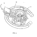
- a liquid heating appliance such as a kettle or a hot water jug is described for reference purposes only. It is provided with a heated base 2 made, typically, from a stainless steel material.
- the base 2 is provided with a sheathed electric heating element 4 which is attached to the base 2 through a thermal diffusion plate 6 in a known manner.
- a sheathed electric heating element 4 which is attached to the base 2 through a thermal diffusion plate 6 in a known manner.
- the base 2 is provided with a peripheral channel 8 which extends around the entire periphery of the base 2.
- the channel 8 has, at its upper end, a flange 10 which may be used to mount the base 2 in the bottom of the liquid heating chamber 12 of the appliance, as shown schematically in Figure 2.
- the base 2 may form an integral part of the base 2 of the liquid heating chamber 12.
- the channel 8 has an inner wall 14, a bottom wall 16 and an outer wall 18. Bonded e.g. brazed to the inner wall 14 of the channel 8 is a generally L-shaped heat bridge member 20 of copper or other highly thermally conductive material but not in accordance with the invention.
- the lower limb 22 of the heat bridge 20 sits under, and is in good thermal contact with, the bimetallic actuator 24 of a thermally sensitive control unit 26.
- the control unit 26 is one of the Applicant's U18 series of products. These comprise a trip lever 28 which is operated on by the actuator 24 to open sets of contacts 30 in the control unit 22.
- Such control units are well known in the art and further details need not be given here.
- the temperature of the water in the peripheral channel 8 lags behind that of the main body of liquid.
- the relatively cool water within the channel 8 is displaced such that the temperature of the channel wall 14 rises relatively quickly. This rise in temperature is transmitted to the bimetallic actuator 24 which, upon reaching its operating temperature (typically 90 to 95 °C), will operate to trip the trip lever 28 and disconnect the power supply to the heating element 4.
- the actuator 24 will eventually re-set allowing the heater to be re-energised.
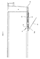
- a heat bridge 31 is provided in thermal contact with the bottom wall 16 of the channel 8.
- the heat bridge 31 comprises two leaves 32, 34 which fit together to define a pocket having the approximate shape of a flattened torus in which the bimetallic actuator 24 is received.
- Each of the leaves 32,34 is somewhat contoured to the curvature of the bimetal 24. They are arranged such that the bimetal 24 lies against the contour of the upper leaf 32 in its ambient configuration. It might also be in contact with the lower leaf 34 along part of its convex surface.
- the lower leaf 34 is formed integrally with a cooling plate 38 which is folded back at an angle of approximately 30 degrees.
- the two leaves 32,34 are held together by a rivet (not shown in the drawings) which also passes through the central tongue of the bimetal 36. This means that the two leaves 32,34 are both in constant direct contact with at least part of the bimetal 24 thereby ensuring good thermal conduction into the bimetal.
- the free edge of the bimetal 24a acts on a push-rod (omitted for clarity) which passes through an aperture in the lower leaf 34.
- peripheral channel sump is not essential and a more traditional cup sump could be employed.
- a bimetallic actuator - another thermal sensor such as a thermistor could be used.
Landscapes
- Engineering & Computer Science (AREA)
- Food Science & Technology (AREA)
- Cookers (AREA)
- Fire-Extinguishing Compositions (AREA)
- Spark Plugs (AREA)
- Non-Insulated Conductors (AREA)
- Reciprocating, Oscillating Or Vibrating Motors (AREA)
- Thermally Actuated Switches (AREA)
Claims (21)
- Elektrische Flüssigkeitskocheinrichtung, wobei die Einrichtung einen Flüssigkeitsheizbehälter mit Heizbasis aufweist, wobei die Basis mit einer Sumpfvertiefung zum Halten von Flüssigkeit und mit einem in Wärmekontakt mit einer Wand der Vertiefung angebrachten Wärmesensor zur Bestimmung des Vorhandenseins von kochender Flüssigkeit in der Vertiefung versehen ist,
dadurch gekennzeichnet, dass
der Wärmesensor in Wärmebrückenanordnung in einer Tasche aufgenommen ist, welche wenigstens teilweise derart gekapselt ist, dass der Luftstrom über den Sensor begrenzt ist. - Einrichtung nach Anspruch 1, wobei der Sensor sich in direktem Kontakt mit der Wärmebrückenanordnung an beiden Seiten befindet.
- Einrichtung nach Anspruch 1 oder 2, wobei die Wärmebrücke wenigstens zwei Blattelemente umfasst und der Wärmesensor wenigstens teilweise zwischen den Blattelementen gekapselt ist.
- Einrichtung nach Anspruch 1, 2 oder 3, wobei die Wärmebrücke derart geformt ist, dass sie sich der Form des Wärmesensors auf wenigstens einer Seite anpasst, um die Übertragung von Wärme durch Wärmeleitung auf denselben zu erhöhen.
- Einrichtung nach einem der vorangehenden Ansprüche, wobei die Wärmebrücke mit einer oder mehreren der Wand/Wände der Sumpfvertiefung verbunden ist.
- Einrichtung nach einem der vorangehenden Ansprüche, wobei die Wärmebrücke in Gebrauch derart angeordnet ist, dass die Rate von von der Sumpfvertiefung über die Wärmebrücke geleiteter Wärmeenergie signifikant größer ist als der Wärmeverlust an die Umgebung.
- Einrichtung nach einem der vorangehenden Ansprüche, wobei die Wärmebrücke aus einem Material mit hoher Wärmeleitfähigkeit gebildet ist, etwa aus Kupfer oder Aluminium.
- Einrichtung nach einem der vorangehenden Ansprüche, wobei die Sumpfvertiefung in der Form eines teilweise oder vollständig ringförmigen Kanals ausgebildet ist.
- Einrichtung nach Anspruch 8, wobei der Kanal um wenigstens einen Teil des Außenumfangs der Heizbasis herum verläuft.
- Einrichtung nach Anspruch 8 oder 9, wobei der Kanal ein Verhältnis der Tiefe zur radialen Breite von größer als Eins aufweist.
- Einrichtung nach Anspruch 8, 9 oder 10 wobei der Kanal an seiner Oberseite eine Breite von weniger als 10% und vorzugsweise von weniger von weniger als 5% des Basisdurchmessers aufweist.
- Einrichtung nach einem der Ansprüche 8 bis 11, wobei der Kanal mit einer oder mehreren Umlenkungen versehen ist, die derart angeordnet sind, dass sie die Bildung von in Umfangsrichtung verlaufenden Strömungen innerhalb des Kanals stören.
- Einrichtung nach einem der Ansprüche 8 bis 12, wobei die Wärmebrücke in Kontakt mit einer oder beiden der radialen Außenwände des Kanals und der Bodenwand des Kanals angebracht ist.
- Einrichtung nach einem der vorangehenden Ansprüche, ferner umfassend ein Kühlelement zum Kühlen der Sumpfvertiefung und/oder des Wärmesensors.
- Einrichtung nach Anspruch 14, wobei die Sumpfvertiefung mit dem Kühlelement versehen ist, das im Bereich des Sensors daran angebracht ist.
- Einrichtung nach Anspruch 14, wobei die Wärmebrücke mit einem Kühlelement versehen ist, das mit Abstand von einer Wand der Sumpfvertiefung angeordnet ist, um es zu ermöglichen, Wärme davon abzuführen.
- Einrichtung nach Anspruch 14, 15, oder 16, wobei die Wärmebrücke und das Kühlelement verschiedene Wärmekapazitäten aufweisen.
- Einrichtung nach einem der vorangehenden Ansprüche, wobei der Wärmesensor ein wärmeempfindlicher Auslöser ist, der in dem Fall, dass Flüssigkeit in dem Gefäß kocht, auslösbar ist.
- Einrichtung nach Anspruch 18, wobei der Auslöser ein Bimetall-Auslöser ist.
- Einrichtung nach Anspruch 18 oder 19, wobei der Auslöser Teil einer wärmeempfindlichen Steuer/Regeleinheit ist.
- Einrichtung nach Anspruch 20, wobei der Auslöser derart wirkt, dass er einen Auslösehebel in der Steuerung/Regelung betätigt, um einen Satz von Kontakten zum Ausschalten oder Verringern der Energiezufuhr zu der Heizbasis zu öffnen.
Applications Claiming Priority (1)
| Application Number | Priority Date | Filing Date | Title |
|---|---|---|---|
| GBGB0421524.0A GB0421524D0 (en) | 2004-09-28 | 2004-09-28 | Electric liquid boiling appliances |
Publications (2)
| Publication Number | Publication Date |
|---|---|
| EP1639921A1 EP1639921A1 (de) | 2006-03-29 |
| EP1639921B1 true EP1639921B1 (de) | 2007-01-24 |
Family
ID=33397378
Family Applications (1)
| Application Number | Title | Priority Date | Filing Date |
|---|---|---|---|
| EP05255987A Revoked EP1639921B1 (de) | 2004-09-28 | 2005-09-26 | Elektrischer Wasserkocher |
Country Status (6)
| Country | Link |
|---|---|
| EP (1) | EP1639921B1 (de) |
| CN (1) | CN1781418A (de) |
| AT (1) | ATE352237T1 (de) |
| DE (1) | DE602005000501T2 (de) |
| ES (1) | ES2280070T3 (de) |
| GB (2) | GB0421524D0 (de) |
Family Cites Families (6)
| Publication number | Priority date | Publication date | Assignee | Title |
|---|---|---|---|---|
| GB1542252A (en) | 1975-10-30 | 1979-03-14 | Taylor J | Snap-acting thermally responsive bimetallic actuators |
| CN1143595C (zh) | 1994-06-09 | 2004-03-24 | 施特里克斯有限公司 | 煮沸水器皿的热敏控制器 |
| DE69520563D1 (de) | 1994-12-13 | 2001-05-10 | Strix Ltd | Gefässe zum erhitzen von flüssigkeiten |
| US6153859A (en) | 1995-07-31 | 2000-11-28 | Strix Limited | Liquid heating vessels |
| GB2377608B (en) | 2001-04-23 | 2005-09-07 | Strix Ltd | Electric heaters |
| GB2399735B (en) * | 2003-03-25 | 2006-04-26 | Strix Ltd | Electric liquid boiling appliances |
-
2004
- 2004-09-28 GB GBGB0421524.0A patent/GB0421524D0/en not_active Ceased
-
2005
- 2005-09-26 GB GB0519587A patent/GB2418581A/en not_active Withdrawn
- 2005-09-26 AT AT05255987T patent/ATE352237T1/de not_active IP Right Cessation
- 2005-09-26 DE DE602005000501T patent/DE602005000501T2/de not_active Revoked
- 2005-09-26 ES ES05255987T patent/ES2280070T3/es active Active
- 2005-09-26 EP EP05255987A patent/EP1639921B1/de not_active Revoked
- 2005-09-28 CN CN200510124987.9A patent/CN1781418A/zh active Pending
Also Published As
| Publication number | Publication date |
|---|---|
| CN1781418A (zh) | 2006-06-07 |
| DE602005000501T2 (de) | 2007-05-24 |
| DE602005000501D1 (de) | 2007-03-15 |
| GB2418581A (en) | 2006-03-29 |
| GB0519587D0 (en) | 2005-11-02 |
| ATE352237T1 (de) | 2007-02-15 |
| GB0421524D0 (en) | 2004-10-27 |
| ES2280070T3 (es) | 2007-09-01 |
| EP1639921A1 (de) | 2006-03-29 |
Similar Documents
| Publication | Publication Date | Title |
|---|---|---|
| US6153859A (en) | Liquid heating vessels | |
| AU682069B2 (en) | Improvements relating to electrically heated water boiling vessels | |
| EP0734215B1 (de) | Vorrichtung zum beheizen von flüssigkeiten | |
| US8299405B2 (en) | Household appliance for heating liquid | |
| CN1327745C (zh) | 厚膜加热器和液体加热装置 | |
| US5706390A (en) | Electrically powered immersion heating elements and controls therefor | |
| GB2344744A (en) | Electrical beverage making apparatus | |
| EP0528656B1 (de) | Flüssigkeitsheizvorrichtungen | |
| JP2001507500A (ja) | 調理場所のための放射加熱体 | |
| GB2409341A (en) | Improvements relating to thermal control units | |
| EP1381299B1 (de) | Elektrische heizelemente | |
| WO1995034188A1 (en) | Liquid heating vessels | |
| EP1639921A1 (de) | Elektrischer Wasserkocher | |
| EP1462039B1 (de) | Elektrisches Gerät zum Kochen von Flüssigkeiten | |
| GB2308743A (en) | Liquid heating vessels | |
| EP1445985A2 (de) | Elektrische Heizelemente | |
| EP1762161B1 (de) | Wasserkocher | |
| GB2265071A (en) | Thermal path to a thermal cut out/ boiling sensor for an electric immmersion heating element | |
| KR200186603Y1 (ko) | 전열기용 온도감지 스위치소자 | |
| GB2365302A (en) | Liquid heating vessels and controls therefor | |
| HK1001197A (en) | Liquid heating vessels |
Legal Events
| Date | Code | Title | Description |
|---|---|---|---|
| PUAI | Public reference made under article 153(3) epc to a published international application that has entered the european phase |
Free format text: ORIGINAL CODE: 0009012 |
|
| AK | Designated contracting states |
Kind code of ref document: A1 Designated state(s): AT BE BG CH CY CZ DE DK EE ES FI FR GB GR HU IE IS IT LI LT LU LV MC NL PL PT RO SE SI SK TR |
|
| AX | Request for extension of the european patent |
Extension state: AL BA HR MK YU |
|
| 17P | Request for examination filed |
Effective date: 20060329 |
|
| GRAP | Despatch of communication of intention to grant a patent |
Free format text: ORIGINAL CODE: EPIDOSNIGR1 |
|
| AKX | Designation fees paid |
Designated state(s): AT BE BG CH CY CZ DE DK EE ES FI FR GB GR HU IE IS IT LI LT LU LV MC NL PL PT RO SE SI SK TR |
|
| GRAS | Grant fee paid |
Free format text: ORIGINAL CODE: EPIDOSNIGR3 |
|
| GRAA | (expected) grant |
Free format text: ORIGINAL CODE: 0009210 |
|
| AK | Designated contracting states |
Kind code of ref document: B1 Designated state(s): AT BE BG CH CY CZ DE DK EE ES FI FR GB GR HU IE IS IT LI LT LU LV MC NL PL PT RO SE SI SK TR |
|
| PG25 | Lapsed in a contracting state [announced via postgrant information from national office to epo] |
Ref country code: AT Free format text: LAPSE BECAUSE OF FAILURE TO SUBMIT A TRANSLATION OF THE DESCRIPTION OR TO PAY THE FEE WITHIN THE PRESCRIBED TIME-LIMIT Effective date: 20070124 Ref country code: DK Free format text: LAPSE BECAUSE OF FAILURE TO SUBMIT A TRANSLATION OF THE DESCRIPTION OR TO PAY THE FEE WITHIN THE PRESCRIBED TIME-LIMIT Effective date: 20070124 Ref country code: CH Free format text: LAPSE BECAUSE OF FAILURE TO SUBMIT A TRANSLATION OF THE DESCRIPTION OR TO PAY THE FEE WITHIN THE PRESCRIBED TIME-LIMIT Effective date: 20070124 Ref country code: SI Free format text: LAPSE BECAUSE OF FAILURE TO SUBMIT A TRANSLATION OF THE DESCRIPTION OR TO PAY THE FEE WITHIN THE PRESCRIBED TIME-LIMIT Effective date: 20070124 Ref country code: PL Free format text: LAPSE BECAUSE OF FAILURE TO SUBMIT A TRANSLATION OF THE DESCRIPTION OR TO PAY THE FEE WITHIN THE PRESCRIBED TIME-LIMIT Effective date: 20070124 Ref country code: LI Free format text: LAPSE BECAUSE OF FAILURE TO SUBMIT A TRANSLATION OF THE DESCRIPTION OR TO PAY THE FEE WITHIN THE PRESCRIBED TIME-LIMIT Effective date: 20070124 Ref country code: FI Free format text: LAPSE BECAUSE OF FAILURE TO SUBMIT A TRANSLATION OF THE DESCRIPTION OR TO PAY THE FEE WITHIN THE PRESCRIBED TIME-LIMIT Effective date: 20070124 |
|
| REG | Reference to a national code |
Ref country code: GB Ref legal event code: FG4D |
|
| REG | Reference to a national code |
Ref country code: CH Ref legal event code: EP |
|
| REG | Reference to a national code |
Ref country code: IE Ref legal event code: FG4D |
|
| REF | Corresponds to: |
Ref document number: 602005000501 Country of ref document: DE Date of ref document: 20070315 Kind code of ref document: P |
|
| PG25 | Lapsed in a contracting state [announced via postgrant information from national office to epo] |
Ref country code: BG Free format text: LAPSE BECAUSE OF FAILURE TO SUBMIT A TRANSLATION OF THE DESCRIPTION OR TO PAY THE FEE WITHIN THE PRESCRIBED TIME-LIMIT Effective date: 20070424 Ref country code: SE Free format text: LAPSE BECAUSE OF FAILURE TO SUBMIT A TRANSLATION OF THE DESCRIPTION OR TO PAY THE FEE WITHIN THE PRESCRIBED TIME-LIMIT Effective date: 20070424 |
|
| PG25 | Lapsed in a contracting state [announced via postgrant information from national office to epo] |
Ref country code: IS Free format text: LAPSE BECAUSE OF FAILURE TO SUBMIT A TRANSLATION OF THE DESCRIPTION OR TO PAY THE FEE WITHIN THE PRESCRIBED TIME-LIMIT Effective date: 20070524 |
|
| ET | Fr: translation filed | ||
| PG25 | Lapsed in a contracting state [announced via postgrant information from national office to epo] |
Ref country code: PT Free format text: LAPSE BECAUSE OF FAILURE TO SUBMIT A TRANSLATION OF THE DESCRIPTION OR TO PAY THE FEE WITHIN THE PRESCRIBED TIME-LIMIT Effective date: 20070625 |
|
| REG | Reference to a national code |
Ref country code: CH Ref legal event code: PL |
|
| REG | Reference to a national code |
Ref country code: ES Ref legal event code: FG2A Ref document number: 2280070 Country of ref document: ES Kind code of ref document: T3 |
|
| PGFP | Annual fee paid to national office [announced via postgrant information from national office to epo] |
Ref country code: ES Payment date: 20070917 Year of fee payment: 3 |
|
| PLBI | Opposition filed |
Free format text: ORIGINAL CODE: 0009260 |
|
| PG25 | Lapsed in a contracting state [announced via postgrant information from national office to epo] |
Ref country code: SK Free format text: LAPSE BECAUSE OF FAILURE TO SUBMIT A TRANSLATION OF THE DESCRIPTION OR TO PAY THE FEE WITHIN THE PRESCRIBED TIME-LIMIT Effective date: 20070124 |
|
| PLAX | Notice of opposition and request to file observation + time limit sent |
Free format text: ORIGINAL CODE: EPIDOSNOBS2 |
|
| 26 | Opposition filed |
Opponent name: AEG HAUSGERAETE GMBH Effective date: 20071024 |
|
| PG25 | Lapsed in a contracting state [announced via postgrant information from national office to epo] |
Ref country code: BE Free format text: LAPSE BECAUSE OF FAILURE TO SUBMIT A TRANSLATION OF THE DESCRIPTION OR TO PAY THE FEE WITHIN THE PRESCRIBED TIME-LIMIT Effective date: 20070124 Ref country code: RO Free format text: LAPSE BECAUSE OF FAILURE TO SUBMIT A TRANSLATION OF THE DESCRIPTION OR TO PAY THE FEE WITHIN THE PRESCRIBED TIME-LIMIT Effective date: 20070124 Ref country code: CZ Free format text: LAPSE BECAUSE OF FAILURE TO SUBMIT A TRANSLATION OF THE DESCRIPTION OR TO PAY THE FEE WITHIN THE PRESCRIBED TIME-LIMIT Effective date: 20070124 |
|
| PG25 | Lapsed in a contracting state [announced via postgrant information from national office to epo] |
Ref country code: LV Free format text: LAPSE BECAUSE OF FAILURE TO SUBMIT A TRANSLATION OF THE DESCRIPTION OR TO PAY THE FEE WITHIN THE PRESCRIBED TIME-LIMIT Effective date: 20070124 |
|
| NLR1 | Nl: opposition has been filed with the epo |
Opponent name: AEG HAUSGERAETE GMBH |
|
| PG25 | Lapsed in a contracting state [announced via postgrant information from national office to epo] |
Ref country code: LT Free format text: LAPSE BECAUSE OF FAILURE TO SUBMIT A TRANSLATION OF THE DESCRIPTION OR TO PAY THE FEE WITHIN THE PRESCRIBED TIME-LIMIT Effective date: 20070124 |
|
| PLBB | Reply of patent proprietor to notice(s) of opposition received |
Free format text: ORIGINAL CODE: EPIDOSNOBS3 |
|
| PG25 | Lapsed in a contracting state [announced via postgrant information from national office to epo] |
Ref country code: MC Free format text: LAPSE BECAUSE OF NON-PAYMENT OF DUE FEES Effective date: 20070930 Ref country code: GR Free format text: LAPSE BECAUSE OF FAILURE TO SUBMIT A TRANSLATION OF THE DESCRIPTION OR TO PAY THE FEE WITHIN THE PRESCRIBED TIME-LIMIT Effective date: 20070425 |
|
| PG25 | Lapsed in a contracting state [announced via postgrant information from national office to epo] |
Ref country code: IE Free format text: LAPSE BECAUSE OF NON-PAYMENT OF DUE FEES Effective date: 20070926 |
|
| PGFP | Annual fee paid to national office [announced via postgrant information from national office to epo] |
Ref country code: FR Payment date: 20080912 Year of fee payment: 4 Ref country code: NL Payment date: 20080925 Year of fee payment: 4 |
|
| PG25 | Lapsed in a contracting state [announced via postgrant information from national office to epo] |
Ref country code: EE Free format text: LAPSE BECAUSE OF FAILURE TO SUBMIT A TRANSLATION OF THE DESCRIPTION OR TO PAY THE FEE WITHIN THE PRESCRIBED TIME-LIMIT Effective date: 20070124 |
|
| PGFP | Annual fee paid to national office [announced via postgrant information from national office to epo] |
Ref country code: DE Payment date: 20080926 Year of fee payment: 4 |
|
| PG25 | Lapsed in a contracting state [announced via postgrant information from national office to epo] |
Ref country code: CY Free format text: LAPSE BECAUSE OF FAILURE TO SUBMIT A TRANSLATION OF THE DESCRIPTION OR TO PAY THE FEE WITHIN THE PRESCRIBED TIME-LIMIT Effective date: 20070124 |
|
| PG25 | Lapsed in a contracting state [announced via postgrant information from national office to epo] |
Ref country code: LU Free format text: LAPSE BECAUSE OF NON-PAYMENT OF DUE FEES Effective date: 20070926 |
|
| PG25 | Lapsed in a contracting state [announced via postgrant information from national office to epo] |
Ref country code: TR Free format text: LAPSE BECAUSE OF FAILURE TO SUBMIT A TRANSLATION OF THE DESCRIPTION OR TO PAY THE FEE WITHIN THE PRESCRIBED TIME-LIMIT Effective date: 20070124 Ref country code: HU Free format text: LAPSE BECAUSE OF FAILURE TO SUBMIT A TRANSLATION OF THE DESCRIPTION OR TO PAY THE FEE WITHIN THE PRESCRIBED TIME-LIMIT Effective date: 20070725 |
|
| REG | Reference to a national code |
Ref country code: ES Ref legal event code: FD2A Effective date: 20080927 |
|
| PG25 | Lapsed in a contracting state [announced via postgrant information from national office to epo] |
Ref country code: ES Free format text: LAPSE BECAUSE OF NON-PAYMENT OF DUE FEES Effective date: 20080927 |
|
| RDAF | Communication despatched that patent is revoked |
Free format text: ORIGINAL CODE: EPIDOSNREV1 |
|
| GBPC | Gb: european patent ceased through non-payment of renewal fee |
Effective date: 20090926 |
|
| RDAG | Patent revoked |
Free format text: ORIGINAL CODE: 0009271 |
|
| STAA | Information on the status of an ep patent application or granted ep patent |
Free format text: STATUS: PATENT REVOKED |
|
| REG | Reference to a national code |
Ref country code: NL Ref legal event code: V1 Effective date: 20100401 |
|
| REG | Reference to a national code |
Ref country code: FR Ref legal event code: ST Effective date: 20100531 |
|
| 27W | Patent revoked |
Effective date: 20100306 |
|
| PG25 | Lapsed in a contracting state [announced via postgrant information from national office to epo] |
Ref country code: FR Free format text: LAPSE BECAUSE OF NON-PAYMENT OF DUE FEES Effective date: 20090930 |
|
| PG25 | Lapsed in a contracting state [announced via postgrant information from national office to epo] |
Ref country code: GB Free format text: LAPSE BECAUSE OF NON-PAYMENT OF DUE FEES Effective date: 20090926 |
|
| PGFP | Annual fee paid to national office [announced via postgrant information from national office to epo] |
Ref country code: IT Payment date: 20080930 Year of fee payment: 4 |