EP1640248A2 - Procédé de montage d'un capteur d'angle et de couple de braquage et boîte de direction avec un capteur d'angle et de couple de braquage - Google Patents
Procédé de montage d'un capteur d'angle et de couple de braquage et boîte de direction avec un capteur d'angle et de couple de braquage Download PDFInfo
- Publication number
- EP1640248A2 EP1640248A2 EP05020817A EP05020817A EP1640248A2 EP 1640248 A2 EP1640248 A2 EP 1640248A2 EP 05020817 A EP05020817 A EP 05020817A EP 05020817 A EP05020817 A EP 05020817A EP 1640248 A2 EP1640248 A2 EP 1640248A2
- Authority
- EP
- European Patent Office
- Prior art keywords
- steering
- housing
- rotor
- steering gear
- sensor
- Prior art date
- Legal status (The legal status is an assumption and is not a legal conclusion. Google has not performed a legal analysis and makes no representation as to the accuracy of the status listed.)
- Granted
Links
Images



Classifications
-
- B—PERFORMING OPERATIONS; TRANSPORTING
- B62—LAND VEHICLES FOR TRAVELLING OTHERWISE THAN ON RAILS
- B62D—MOTOR VEHICLES; TRAILERS
- B62D15/00—Steering not otherwise provided for
- B62D15/02—Steering position indicators ; Steering position determination; Steering aids
- B62D15/021—Determination of steering angle
-
- B—PERFORMING OPERATIONS; TRANSPORTING
- B62—LAND VEHICLES FOR TRAVELLING OTHERWISE THAN ON RAILS
- B62D—MOTOR VEHICLES; TRAILERS
- B62D15/00—Steering not otherwise provided for
- B62D15/02—Steering position indicators ; Steering position determination; Steering aids
-
- B—PERFORMING OPERATIONS; TRANSPORTING
- B62—LAND VEHICLES FOR TRAVELLING OTHERWISE THAN ON RAILS
- B62D—MOTOR VEHICLES; TRAILERS
- B62D15/00—Steering not otherwise provided for
- B62D15/02—Steering position indicators ; Steering position determination; Steering aids
- B62D15/021—Determination of steering angle
- B62D15/0215—Determination of steering angle by measuring on the steering column
-
- B—PERFORMING OPERATIONS; TRANSPORTING
- B62—LAND VEHICLES FOR TRAVELLING OTHERWISE THAN ON RAILS
- B62D—MOTOR VEHICLES; TRAILERS
- B62D6/00—Arrangements for automatically controlling steering depending on driving conditions sensed and responded to, e.g. control circuits
- B62D6/08—Arrangements for automatically controlling steering depending on driving conditions sensed and responded to, e.g. control circuits responsive only to driver input torque
- B62D6/10—Arrangements for automatically controlling steering depending on driving conditions sensed and responded to, e.g. control circuits responsive only to driver input torque characterised by means for sensing or determining torque
Definitions
- the invention relates to a method for mounting a steering angle and steering torque sensor to a steering gear.
- the invention further relates to a steering gear with a steering angle and steering torque sensor.
- the steering angle and steering torque sensors are used to provide various data to a power steering control unit or an electronic stability programmer.
- the problem is the installation of the sensor in the steering gear. If the steering gear is in the neutral position, which corresponds to a straight ahead driving of the vehicle, the sensor for the steering angle should give a signal, which also corresponds to the zero position. This could be ensured if all components of the steering gear are assembled, brought into the zero position and then the sensor could be firmly connected to the steering shaft and the housing of the steering gear. For space reasons, however, this is not possible because after mounting the sensor in the steering gear, the various components are hardly accessible.
- the object of the invention is a method for mounting a steering angle and steering torque sensor to a steering gear and a To provide steering gear, in which the sensor, when the steering gear is in the neutral position, is also in the zero position with high accuracy.
- a steering angle and steering torque sensor which has a housing and a rotor.
- the rotor is rotated relative to the housing by a predetermined angular amount relative to a zero position.
- the rotor is attached to a steering shaft, which is provided with a pinion toothing.
- the steering shaft is inserted into a steering gear having a rack, wherein the housing is fixed in a predetermined angular position on the steering gear and the steering shaft is rotated together with the rotor by the engagement of the pinion teeth in the rack until the rotor relative to the housing zero position reached again.
- the method according to the invention is based on the basic idea of "detuning" the sensor by exactly the angular amount by which the steering shaft is necessarily rotated during assembly in the steering gear. Since the steering shaft engages without play in the rack of the steering gear, which can be determined from the assembly rotation of the steering shaft with high accuracy. If the rotor and the housing of the sensor are rotated against each other with the same high accuracy before assembly, the zero position of the sensor is obtained with correspondingly high accuracy after assembly.
- the only tolerant mounting step namely the rotation of the housing and the rotor of the sensor against each other, can be made in a state in which all components are easily accessible, namely outside of the steering gear.
- a steering gear with a steering angle and steering torque sensor comprising a housing and a rotor, wherein the housing is fixed by means of a sliding guide on the steering gear.
- the sliding guide ensures that the housing of the sensor is rotatably coupled to the steering gear.
- a steering gear 10 is shown schematically, which has a steering gear housing 12, a rack 14 slidably disposed therein with a toothing 16 and a steering shaft 18.
- the steering shaft has a pinion toothing 20, which is provided in the toothing 16 of the Rack 14 to intervene. Both the teeth 16 and the pinion teeth 20 are helical gears.
- On the steering shaft 18 is also a steering angle and steering torque sensor 22 (see also Figures 4 and 5) attached.
- This has, as essential components, a housing 24 and a rotor 26.
- the housing 24 is intended to be fixedly mounted on the steering gear 10, and the rotor 26 is rotatably mounted on the steering shaft 18.
- the housing 24 also has a coil spring housing 27, inside which a coil spring is arranged, which allows an electrical connection to various components of the rotor over several revolutions in one or the other direction.
- the housing 24 of the sensor 22 is provided on its outside with two protruding lugs 28 which serve to fix the housing relative to the steering shaft housing 12.
- the steering shaft housing has complementary shaped recesses. In this way, a sliding guide is formed.
- a connector 29 is also provided, in which a complementary connector can engage, so that the sensor 22 can be connected to a control electronics.
- the rack 14 is brought in the steering gear housing 12 in its central position or neutral position.
- the sensor 22 is attached to the steering shaft 18. More specifically, the rotor 26 of the sensor 22 is rotatably attached to the steering shaft 18. For this purpose, noses, grooves, splines or other designs may be used. Then, the rotor 26 is rotated relative to the housing 24 by a predetermined angle from the Nullage out. This is indicated in Figure 1, characterized in that shown for explanation position marks 30 which correspond to the zero position, compared to the zero position is rotated by about 90 °. The zero position corresponds to the visible in Figure 1 nose 28 on the housing 24.
- the rotor 26 In this twisted position, the rotor 26 is locked relative to the housing 24 by a locking means 32 (see Figures 4 and 5).
- the locking means 32 is in particular a clip which in suitable recesses on the rotor 26 and engages the housing 24 and locks the sensor in its twisted out of the zero position position.
- the steering shaft 18 When the steering shaft 18 is inserted into the steering gear housing 12 together with the attached thereto sensor 22, it is first aligned visually correct and used with the pinion teeth 20 in the rack. This is easily possible because the pinion gearing according to the number of teeth only pretends few positions that differ so much in their orientation from each other that only visually the right one can be selected. then the steering shaft is inserted into the housing until the lugs 28 engage the housing 24 of the sensor 22 in the associated recesses on the steering gear housing 12 and position the housing 24 correctly. After the lugs 28 of the housing 24 of the sensor 22 are fixed relative to the steering gear housing 12, the locking means 32 is removed.
- the steering shaft 18 When the steering shaft 18 is further inserted, the steering shaft 18 is rotated relative to the housing 24 of the sensor 22, since the pinion teeth 20 together with the teeth 16 of the rack 14 causes a forced rotation, while the housing 24 of the sensor 22 via the lugs 28 rotatably relative is held to the steering gear housing 12.
- the steering shaft 18 can be seen during insertion into the steering gear housing 12; the steering shaft 18 has thereby approximated from its rotated position of the zero position. Accordingly, the position marks 30 have moved closer to the zero position.
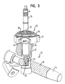
- the steering gear 10 is shown with fully inserted steering shaft 18.
- the steering shaft 18 has rotated back to its neutral position or center position.
- the rotor 26 is relative to the housing 24 of the sensor 22 again in the zero position.
- the position marks 30 are located Accordingly, at the same radius as the nose shown in Figure 1 on the housing 24. Therefore, now the recesses into which the locking means 32 was inserted on the housing 24 and the rotor 26, rotated by the angular amount to each other, by which the sensor 22 prior to assembly was twisted out of its zero position.
- the connector 29 is now behind a recess 34 in the steering gear housing 12, so that it can be easily contacted by means of a complementary connector. This also provides the necessary seal in the recess 34.
- the predetermined angular amount by which the rotor 26 has been rotated relative to the housing 24 of the sensor 22 from the zero position is equal to the angular amount by which the steering shaft 18 upon insertion into the steering gear housing 12 by engaging two helical gears is twisted into each other.
Landscapes
- Engineering & Computer Science (AREA)
- Chemical & Material Sciences (AREA)
- Combustion & Propulsion (AREA)
- Transportation (AREA)
- Mechanical Engineering (AREA)
- Power Steering Mechanism (AREA)
- Length Measuring Devices With Unspecified Measuring Means (AREA)
- Force Measurement Appropriate To Specific Purposes (AREA)
- Steering Controls (AREA)
- Measurement Of Length, Angles, Or The Like Using Electric Or Magnetic Means (AREA)
Priority Applications (1)
| Application Number | Priority Date | Filing Date | Title |
|---|---|---|---|
| PL05020817T PL1640248T3 (pl) | 2004-09-28 | 2005-09-23 | Sposób montażu czujnika kąta skrętu koła kierowanego i momentu skrętu koła kierowanego oraz mechanizm kierowniczy z czujnikiem kąta skrętu koła kierowanego i momentu skrętu koła kierowanego |
Applications Claiming Priority (1)
| Application Number | Priority Date | Filing Date | Title |
|---|---|---|---|
| DE102004046946A DE102004046946B4 (de) | 2004-09-28 | 2004-09-28 | Verfahren zur Montage eines Lenkwinkel- und Lenkmomentsensors sowie Lenkgetriebe mit einem Lenkwinkel- und Lenkmomentsensor |
Publications (3)
| Publication Number | Publication Date |
|---|---|
| EP1640248A2 true EP1640248A2 (fr) | 2006-03-29 |
| EP1640248A3 EP1640248A3 (fr) | 2006-06-07 |
| EP1640248B1 EP1640248B1 (fr) | 2008-05-28 |
Family
ID=35445758
Family Applications (1)
| Application Number | Title | Priority Date | Filing Date |
|---|---|---|---|
| EP05020817A Expired - Lifetime EP1640248B1 (fr) | 2004-09-28 | 2005-09-23 | Procédé de montage d'un capteur d'angle et de couple de braquage et boîte de direction avec un capteur d'angle et de couple de braquage |
Country Status (5)
| Country | Link |
|---|---|
| US (1) | US7350617B2 (fr) |
| EP (1) | EP1640248B1 (fr) |
| JP (1) | JP4897264B2 (fr) |
| DE (2) | DE102004046946B4 (fr) |
| PL (1) | PL1640248T3 (fr) |
Families Citing this family (13)
| Publication number | Priority date | Publication date | Assignee | Title |
|---|---|---|---|---|
| JP2007196927A (ja) * | 2006-01-27 | 2007-08-09 | Showa Corp | 電動舵取装置 |
| JP5397658B2 (ja) * | 2008-02-12 | 2014-01-22 | 株式会社ジェイテクト | 車両用操舵装置及びそのサブアセンブリの移送方法 |
| KR101528837B1 (ko) * | 2008-09-16 | 2015-06-16 | 현대모비스 주식회사 | 조향장치의 토크센서장치 |
| KR101452559B1 (ko) | 2011-12-06 | 2014-10-21 | 주식회사 만도 | 피니언 센서 어셈블리와 피니언 센서 커버 어셈블리 및 이를 구비한 전동식 동력 보조 조향장치 |
| CN104111021B (zh) * | 2014-07-08 | 2016-08-03 | 湖北三江航天红峰控制有限公司 | 一种空气舵机舵片角度与电气角度重合调零执行机构 |
| KR102327241B1 (ko) * | 2015-08-18 | 2021-11-17 | 현대모비스 주식회사 | 전동식 조향장치 |
| DE102017118457B4 (de) * | 2017-08-14 | 2021-06-10 | Danfoss Power Solutions Aps | Lenkhandradwinkelsensoranordnung einer hydraulischen Lenkanordnung |
| JP2019147605A (ja) * | 2018-02-28 | 2019-09-05 | 凸版印刷株式会社 | スタンディングパウチ |
| CN109367614A (zh) * | 2018-12-14 | 2019-02-22 | 东风柳州汽车有限公司 | 转向管柱总成 |
| CN110497961B (zh) * | 2019-08-26 | 2021-04-20 | 北京汽车股份有限公司 | 转向器的中间位置回正系统和方法 |
| US11661101B2 (en) | 2020-08-17 | 2023-05-30 | Honda Motor Co., Ltd. | Setting vehicle center in electronic power steering system |
| DE102021213883A1 (de) * | 2021-12-07 | 2023-06-07 | Zf Friedrichshafen Ag | Verfahren zur Herstellung einer Baugruppe für eine Lenkvorrichtung |
| KR20230139887A (ko) * | 2022-03-24 | 2023-10-06 | 에이치엘만도 주식회사 | 조향장치의 피니언 센서 구조체 및 조향장치의 피니언 센서 구조체의 조립 방법 |
Family Cites Families (15)
| Publication number | Priority date | Publication date | Assignee | Title |
|---|---|---|---|---|
| DE3703591A1 (de) * | 1987-02-06 | 1988-08-18 | Audi Ag | Vorrichtung zum erzeugen eines elektrischen signales |
| JPH0429515Y2 (fr) * | 1987-10-17 | 1992-07-16 | ||
| US5243188A (en) * | 1991-09-26 | 1993-09-07 | Kabushiki Kaisha Tokai Rika Denki Seisakusho | Neutral position detector for steering wheels having a first and second rotors with aligned slots |
| DE19703903A1 (de) * | 1997-02-03 | 1998-08-13 | Bosch Gmbh Robert | Lenkwinkelsensor |
| US6366080B1 (en) * | 1997-04-24 | 2002-04-02 | Trw Fahrwerksysteme Gmbh & Co. Kg | Sensor for sensing rotary movement including a stationary sensor unit and a rotatable sensor unit |
| DE19718723C2 (de) * | 1997-05-02 | 2003-01-30 | Trw Fahrwerksyst Gmbh & Co | Drehsensor-Anordnung |
| DE19935283A1 (de) * | 1999-07-27 | 2000-11-02 | Zf Lenksysteme Gmbh | Elektrisch unterstützte Hilfskraftlenkung für Kraftfahrzeuge |
| JP3815994B2 (ja) * | 2001-10-01 | 2006-08-30 | 株式会社ジェイテクト | ステアリング装置 |
| US6844541B2 (en) * | 2002-02-15 | 2005-01-18 | Methode Electronics, Inc. | Rapid high resolution position sensor for auto steering |
| DE10236142A1 (de) * | 2002-08-07 | 2004-02-19 | Valeo Schalter Und Sensoren Gmbh | Lenkstockmodul und Montageverfahren |
| JP2004184394A (ja) * | 2002-10-11 | 2004-07-02 | Furukawa Electric Co Ltd:The | 回転センサ |
| EP1413499B1 (fr) * | 2002-10-24 | 2008-02-13 | Jtekt Corporation | Capteur d'angle de direction pour un dispositif de direction assistée |
| JP4320587B2 (ja) * | 2003-11-28 | 2009-08-26 | 株式会社ジェイテクト | 電動パワーステアリング装置およびその製造方法 |
| EP1674343B1 (fr) * | 2004-12-23 | 2008-02-27 | Delphi Technologies, Inc. | Dispositif de connection électrique |
| DE102005053183A1 (de) * | 2005-11-03 | 2007-05-10 | Valeo Schalter Und Sensoren Gmbh | Baugruppe für ein Lenksystem eines Kraftfahrzeugs |
-
2004
- 2004-09-28 DE DE102004046946A patent/DE102004046946B4/de not_active Expired - Fee Related
-
2005
- 2005-09-23 PL PL05020817T patent/PL1640248T3/pl unknown
- 2005-09-23 EP EP05020817A patent/EP1640248B1/fr not_active Expired - Lifetime
- 2005-09-23 DE DE502005004254T patent/DE502005004254D1/de not_active Expired - Lifetime
- 2005-09-28 JP JP2005281378A patent/JP4897264B2/ja not_active Expired - Fee Related
- 2005-09-28 US US11/238,093 patent/US7350617B2/en active Active
Non-Patent Citations (1)
| Title |
|---|
| None |
Also Published As
| Publication number | Publication date |
|---|---|
| US7350617B2 (en) | 2008-04-01 |
| DE102004046946B4 (de) | 2013-10-02 |
| JP2006096338A (ja) | 2006-04-13 |
| PL1640248T3 (pl) | 2008-10-31 |
| EP1640248B1 (fr) | 2008-05-28 |
| JP4897264B2 (ja) | 2012-03-14 |
| DE102004046946A1 (de) | 2006-04-06 |
| DE502005004254D1 (de) | 2008-07-10 |
| US20060065473A1 (en) | 2006-03-30 |
| EP1640248A3 (fr) | 2006-06-07 |
Similar Documents
| Publication | Publication Date | Title |
|---|---|---|
| DE69832113T2 (de) | Verriegelungsvorrichtung für die Lenkung | |
| EP1110828B1 (fr) | Dispositif de verrouillage | |
| EP1640248B1 (fr) | Procédé de montage d'un capteur d'angle et de couple de braquage et boîte de direction avec un capteur d'angle et de couple de braquage | |
| EP1232921B1 (fr) | Système de verouillage | |
| DE9116447U1 (de) | Elektromotorischer Antrieb für eine Zentralverriegelungsvorrichtung an einem Kraftfahrzeug | |
| EP2261445B1 (fr) | Serrure, notamment serrure de porte dotée d'un mécanisme de fermeture amélioré | |
| EP3776750B1 (fr) | Pièce de connecteur électrique et système de connexion électrique avec verrouillage | |
| EP0786162B1 (fr) | Dispositif de connexion electrique | |
| DE4141007A1 (de) | Kabelverbinder fuer eine lenkschlosseinrichtung | |
| EP2070781B1 (fr) | Dispositif de verrouillage compact doté d'un élément de sécurité | |
| DE3007096C2 (de) | Einfach-Rotations-Kupplung, insbesondere für Frankiermaschinen | |
| DE102020213568A1 (de) | Verbindung zwischen einem Schalthebel und einer Verbindungsstange einer Parksperre eines Kraftfahrzeugs | |
| DE2136528C3 (de) | Uhr mit einer Einstell- und Aufzieheinrichtung | |
| DE2631589A1 (de) | Vorrichtung mit skala zum zaehlen von umdrehungen | |
| DE9219075U1 (de) | Betätigungsgetriebe für Beschläge an Fenstern, Türen o.dgl. | |
| DE102017212073A1 (de) | Zahnstangengetriebe für ein Kraftfahrzeug | |
| DE102018125973A1 (de) | Aktuatorvorrichtung für eine elektromechanische Lenkungsanordnung | |
| DE19541091A1 (de) | Drehbare Verbindungseinrichtung | |
| EP2603775A1 (fr) | Dispositif de détermination de la position angulaire d'un composant rotatif d'un véhicule, et véhicule équipé d'un tel dispositif | |
| DE102021103622A1 (de) | Dreh-getriebeanordnung zur vergrösserung des hartanschlag-motorweges | |
| DE112020002351T5 (de) | Steer-by-wire-lenkvorrichtung | |
| DE102013010363A1 (de) | Zahnstangenlenkung mit zwei Ritzeln | |
| EP0165484B1 (fr) | Verrou de sûreté à organes de verrouillage rotatifs | |
| DE2452738C3 (de) | Zeitschaltgerät, insbesondere digitale Herdschaltuhr | |
| DE102007058752B4 (de) | Verfahrantrieb für ein Schaltgerät sowie Schaltgerät mit einem derartigen Verfahrantrieb |
Legal Events
| Date | Code | Title | Description |
|---|---|---|---|
| PUAI | Public reference made under article 153(3) epc to a published international application that has entered the european phase |
Free format text: ORIGINAL CODE: 0009012 |
|
| AK | Designated contracting states |
Kind code of ref document: A2 Designated state(s): AT BE BG CH CY CZ DE DK EE ES FI FR GB GR HU IE IS IT LI LT LU LV MC NL PL PT RO SE SI SK TR |
|
| AX | Request for extension of the european patent |
Extension state: AL BA HR MK YU |
|
| PUAL | Search report despatched |
Free format text: ORIGINAL CODE: 0009013 |
|
| AK | Designated contracting states |
Kind code of ref document: A3 Designated state(s): AT BE BG CH CY CZ DE DK EE ES FI FR GB GR HU IE IS IT LI LT LU LV MC NL PL PT RO SE SI SK TR |
|
| AX | Request for extension of the european patent |
Extension state: AL BA HR MK YU |
|
| 17P | Request for examination filed |
Effective date: 20061207 |
|
| AKX | Designation fees paid |
Designated state(s): DE FR PL |
|
| GRAP | Despatch of communication of intention to grant a patent |
Free format text: ORIGINAL CODE: EPIDOSNIGR1 |
|
| GRAS | Grant fee paid |
Free format text: ORIGINAL CODE: EPIDOSNIGR3 |
|
| GRAA | (expected) grant |
Free format text: ORIGINAL CODE: 0009210 |
|
| AK | Designated contracting states |
Kind code of ref document: B1 Designated state(s): DE FR PL |
|
| REF | Corresponds to: |
Ref document number: 502005004254 Country of ref document: DE Date of ref document: 20080710 Kind code of ref document: P |
|
| REG | Reference to a national code |
Ref country code: DE Ref legal event code: R096 Ref document number: 502005004254 Country of ref document: DE Effective date: 20080710 |
|
| REG | Reference to a national code |
Ref country code: PL Ref legal event code: T3 |
|
| PLBE | No opposition filed within time limit |
Free format text: ORIGINAL CODE: 0009261 |
|
| STAA | Information on the status of an ep patent application or granted ep patent |
Free format text: STATUS: NO OPPOSITION FILED WITHIN TIME LIMIT |
|
| 26N | No opposition filed |
Effective date: 20090303 |
|
| REG | Reference to a national code |
Ref country code: DE Ref legal event code: R097 Ref document number: 502005004254 Country of ref document: DE Effective date: 20090303 |
|
| REG | Reference to a national code |
Ref country code: FR Ref legal event code: PLFP Year of fee payment: 12 |
|
| REG | Reference to a national code |
Ref country code: FR Ref legal event code: PLFP Year of fee payment: 13 |
|
| REG | Reference to a national code |
Ref country code: FR Ref legal event code: PLFP Year of fee payment: 14 |
|
| PGFP | Annual fee paid to national office [announced via postgrant information from national office to epo] |
Ref country code: FR Payment date: 20190925 Year of fee payment: 15 |
|
| PGFP | Annual fee paid to national office [announced via postgrant information from national office to epo] |
Ref country code: PL Payment date: 20190903 Year of fee payment: 15 |
|
| PG25 | Lapsed in a contracting state [announced via postgrant information from national office to epo] |
Ref country code: FR Free format text: LAPSE BECAUSE OF NON-PAYMENT OF DUE FEES Effective date: 20200930 |
|
| PG25 | Lapsed in a contracting state [announced via postgrant information from national office to epo] |
Ref country code: PL Free format text: LAPSE BECAUSE OF NON-PAYMENT OF DUE FEES Effective date: 20200923 |
|
| P01 | Opt-out of the competence of the unified patent court (upc) registered |
Effective date: 20230628 |
|
| PGFP | Annual fee paid to national office [announced via postgrant information from national office to epo] |
Ref country code: DE Payment date: 20240702 Year of fee payment: 20 |
|
| REG | Reference to a national code |
Ref country code: DE Ref legal event code: R071 Ref document number: 502005004254 Country of ref document: DE |