EP1640295B1 - Kugelübertragungseinheit und kugeltisch - Google Patents
Kugelübertragungseinheit und kugeltisch Download PDFInfo
- Publication number
- EP1640295B1 EP1640295B1 EP04747141A EP04747141A EP1640295B1 EP 1640295 B1 EP1640295 B1 EP 1640295B1 EP 04747141 A EP04747141 A EP 04747141A EP 04747141 A EP04747141 A EP 04747141A EP 1640295 B1 EP1640295 B1 EP 1640295B1
- Authority
- EP
- European Patent Office
- Prior art keywords
- ball
- main body
- transfer unit
- ball transfer
- small balls
- Prior art date
- Legal status (The legal status is an assumption and is not a legal conclusion. Google has not performed a legal analysis and makes no representation as to the accuracy of the status listed.)
- Revoked
Links
Images

Classifications
-
- H—ELECTRICITY
- H10—SEMICONDUCTOR DEVICES; ELECTRIC SOLID-STATE DEVICES NOT OTHERWISE PROVIDED FOR
- H10P—GENERIC PROCESSES OR APPARATUS FOR THE MANUFACTURE OR TREATMENT OF DEVICES COVERED BY CLASS H10
- H10P72/00—Handling or holding of wafers, substrates or devices during manufacture or treatment thereof
- H10P72/30—Handling or holding of wafers, substrates or devices during manufacture or treatment thereof for conveying, e.g. between different workstations
- H10P72/32—Handling or holding of wafers, substrates or devices during manufacture or treatment thereof for conveying, e.g. between different workstations between different workstations
- H10P72/3202—Mechanical details, e.g. rollers or belts
-
- B—PERFORMING OPERATIONS; TRANSPORTING
- B65—CONVEYING; PACKING; STORING; HANDLING THIN OR FILAMENTARY MATERIAL
- B65G—TRANSPORT OR STORAGE DEVICES, e.g. CONVEYORS FOR LOADING OR TIPPING, SHOP CONVEYOR SYSTEMS OR PNEUMATIC TUBE CONVEYORS
- B65G39/00—Rollers, e.g. drive rollers, or arrangements thereof incorporated in roller-ways or other types of mechanical conveyors
- B65G39/02—Adaptations of individual rollers and supports therefor
- B65G39/025—Adaptations of individual rollers and supports therefor having spherical roller elements
-
- F—MECHANICAL ENGINEERING; LIGHTING; HEATING; WEAPONS; BLASTING
- F16—ENGINEERING ELEMENTS AND UNITS; GENERAL MEASURES FOR PRODUCING AND MAINTAINING EFFECTIVE FUNCTIONING OF MACHINES OR INSTALLATIONS; THERMAL INSULATION IN GENERAL
- F16C—SHAFTS; FLEXIBLE SHAFTS; ELEMENTS OR CRANKSHAFT MECHANISMS; ROTARY BODIES OTHER THAN GEARING ELEMENTS; BEARINGS
- F16C29/00—Bearings for parts moving only linearly
- F16C29/04—Ball or roller bearings
- F16C29/045—Ball or roller bearings having rolling elements journaled in one of the moving parts
- F16C29/046—Ball or roller bearings having rolling elements journaled in one of the moving parts with balls journaled in pockets
-
- H—ELECTRICITY
- H10—SEMICONDUCTOR DEVICES; ELECTRIC SOLID-STATE DEVICES NOT OTHERWISE PROVIDED FOR
- H10P—GENERIC PROCESSES OR APPARATUS FOR THE MANUFACTURE OR TREATMENT OF DEVICES COVERED BY CLASS H10
- H10P72/00—Handling or holding of wafers, substrates or devices during manufacture or treatment thereof
- H10P72/10—Handling or holding of wafers, substrates or devices during manufacture or treatment thereof using carriers specially adapted therefor, e.g. front opening unified pods [FOUP]
- H10P72/16—Trays for chips
-
- H—ELECTRICITY
- H10—SEMICONDUCTOR DEVICES; ELECTRIC SOLID-STATE DEVICES NOT OTHERWISE PROVIDED FOR
- H10P—GENERIC PROCESSES OR APPARATUS FOR THE MANUFACTURE OR TREATMENT OF DEVICES COVERED BY CLASS H10
- H10P72/00—Handling or holding of wafers, substrates or devices during manufacture or treatment thereof
- H10P72/30—Handling or holding of wafers, substrates or devices during manufacture or treatment thereof for conveying, e.g. between different workstations
- H10P72/33—Handling or holding of wafers, substrates or devices during manufacture or treatment thereof for conveying, e.g. between different workstations into and out of processing chamber
- H10P72/3304—Handling or holding of wafers, substrates or devices during manufacture or treatment thereof for conveying, e.g. between different workstations into and out of processing chamber characterised by movements or sequence of movements of transfer devices
-
- H—ELECTRICITY
- H10—SEMICONDUCTOR DEVICES; ELECTRIC SOLID-STATE DEVICES NOT OTHERWISE PROVIDED FOR
- H10P—GENERIC PROCESSES OR APPARATUS FOR THE MANUFACTURE OR TREATMENT OF DEVICES COVERED BY CLASS H10
- H10P72/00—Handling or holding of wafers, substrates or devices during manufacture or treatment thereof
- H10P72/70—Handling or holding of wafers, substrates or devices during manufacture or treatment thereof for supporting or gripping
- H10P72/72—Handling or holding of wafers, substrates or devices during manufacture or treatment thereof for supporting or gripping using electrostatic chucks
- H10P72/722—Details of electrostatic chucks
-
- H—ELECTRICITY
- H10—SEMICONDUCTOR DEVICES; ELECTRIC SOLID-STATE DEVICES NOT OTHERWISE PROVIDED FOR
- H10P—GENERIC PROCESSES OR APPARATUS FOR THE MANUFACTURE OR TREATMENT OF DEVICES COVERED BY CLASS H10
- H10P72/00—Handling or holding of wafers, substrates or devices during manufacture or treatment thereof
- H10P72/70—Handling or holding of wafers, substrates or devices during manufacture or treatment thereof for supporting or gripping
- H10P72/76—Handling or holding of wafers, substrates or devices during manufacture or treatment thereof for supporting or gripping using mechanical means, e.g. clamps or pinches
- H10P72/7602—Handling or holding of wafers, substrates or devices during manufacture or treatment thereof for supporting or gripping using mechanical means, e.g. clamps or pinches the wafers being placed on a robot blade or gripped by a gripper for conveyance
-
- F—MECHANICAL ENGINEERING; LIGHTING; HEATING; WEAPONS; BLASTING
- F16—ENGINEERING ELEMENTS AND UNITS; GENERAL MEASURES FOR PRODUCING AND MAINTAINING EFFECTIVE FUNCTIONING OF MACHINES OR INSTALLATIONS; THERMAL INSULATION IN GENERAL
- F16C—SHAFTS; FLEXIBLE SHAFTS; ELEMENTS OR CRANKSHAFT MECHANISMS; ROTARY BODIES OTHER THAN GEARING ELEMENTS; BEARINGS
- F16C2326/00—Articles relating to transporting
- F16C2326/58—Conveyor systems, e.g. rollers or bearings therefor
Definitions
- the present invention pertains to a ball table, which can support a transported material in such a way that the transported material can displace in any direction along its transport surface, and pertains to a ball transfer unit used for said ball table.
- a ball table having multiple ball transfer units arranged on a fixed disk or other support part is used to correct the transport position of a transported material on its transport path or to change the transport direction to the perpendicular direction.
- the ball transfer unit assembled in such a ball table has a main body having a seat surface recessed in a semispherical shape, multiple small balls rollingly in contact with the seat surface of the main body, a large ball rollingly in contact with the multiple small balls, and a cover installed on the main body to hold the large ball and to hold small balls between the large ball and the seat surface of the main body.
- the static friction resistance between the transported material and the large ball can be reduced to a very low level.
- Patent No. 2641187 disclosed the following technology.
- the side end acting as the positioning reference for automobile window glass with a large weight or other material transported on a ball table is pressed by an actuator against a positioning reference block fixed with respect to the ball table. In this way, the transport position of the transported material is corrected.
- Japanese Kokai Patent Application No. Hei 7[1995]-164078 which is considered to be the closest state of the art, discloses technology about the ball transfer unit itself, in order to prevent the surface of a plate as the transported material from being damaged, or in order to apply a lubricant to the surface of the plate, the ball transfer unit is made of a synthetic resin, which has a self-lubricating property and is softer than metal.
- the ball table can be used for such a positioning operation.
- When transporting a semiconductor wafer or a glass substrate for a flat panel display it is necessary to prevent damage to the surface caused by friction and the attachment of foreign matter. Even if foreign matter is attached, it is necessary to make sure that it can be easily removed by means of washing.
- the invention solves the problem of providing a ball transfer unit that avoids causing damage to the surface of the transported material and minimizing the frictional resistance when transported material is moved from the static state so that the transported material can be moved very smoothly even under high temperature environment.
- the ball transfer unit has a main body having a seat surface recessed in a semispherical shape, multiple small balls rollingly in contact with the seat surface of the main body, a large ball rollingly in contact with the multiple small balls, and a cover installed on the main body to hold the large ball and to hold small balls between the large ball and the seat surface of the main body; at least the aforementioned main body and the aforementioned large ball are made of any material selected from PAI (polyamide imide), PBI (polybenzimidazole), PCTFE (polychlorotrifluoroethylene), PEEK (polyether ether ketone), PEI (polyether imide), PI (polyimide), PPS (polyphenylene sulfide), melamine resin, aromatic polyamide resin (aramide resin), aluminum oxide, zirconium oxide, and silicon nitride.
- PAI polyamide imide
- PBI polybenzimidazole
- PCTFE polychlorotrifluoroethylene
- the large ball rolls along with the displacement of the transported material; the small balls that support the large ball also roll with respect to the seat material of the main body to minimize the frictional resistance with respect to movement of the transported material.
- the main body and the large ball are made of any material selected from PAI, PBI PCTFE, PEEK, PEI, PI, PPS, melamine resin, aromatic polyamide resin, aluminum oxide, zirconium oxide, and silicon nitride, the frictional resistance against movement of the transported material carried on the large ball can be minimized, and the transported material can be displaced by applying a small external force.
- abrasion abrasive powder is difficult to generate along with rolling of the large ball and the small balls. Even if abrasion powder is generated and attaches in traces to the transported material, it can be easily washed off. Consequently, the adverse effect can be prevented before it occurs when processing a semiconductor wafer or manufacturing flat panel display. Also, excellent resistance against UV light or chemical resistance can be obtained.
- the Rockwell hardness H R R (R scale) of the main body, small balls, and large ball is preferred to be 75 or larger. If the Rockwell hardness H R R of these parts is less than 75, the large ball or the seat surface of the main body may undergo elastic deformation under the weight, etc., of the transported material carried on the large ball. The frictional resistance will be increased when the transported material is moved from a static state, to hinder the smooth movement of the transported material. In particular, there is a high possibility of causing damage to the surface of the large ball or having foreign matter attached to the surface of the large ball.
- the thermal deformation temperatures of the main body, small balls, and large ball measured according to test ASTM D648 should be 120°C or higher. If the thermal deformation temperatures are lower than 120°C, when the transported material has a relatively high temperature or is used in an atmosphere with a high environmental temperature, the large ball or the seat surface of the main body may be deformed. The frictional resistance will be increased when the transported material is moved [transformed] from a static state. As a result, smooth movement of the transported material is hindered.
- Said PAI, PBI, PCTFE, PEEK, PEI, PI, PPS, melamine resin, and aromatic polyamide resin all have Rockwell hardness H R R levels of 75 or larger and thermal deformation temperatures measured, according to test standard ASTM D648, of 120°C or higher.
- Rockwell hardness H R R levels 75 or larger and thermal deformation temperatures measured, according to test standard ASTM D648, of 120°C or higher.
- aluminum oxide, zirconium oxide, and silicon nitride are harder and have better heat resistance than the aforementioned resins.
- the small balls can be made of the same material used for the main body or the large ball.
- the small balls can also be made of a stainless steel, such as SUS304, SUS316, SUS420j2, SUS440C, or wet surface-treated (chemical grinding and surface washing) SUS304 and SUS316. If the small balls are made of stainless steel, it is preferred to form the main body and the large ball using PAI, PBI, PCTFE, PEEK, PEI, PI, PPS, melamine resin, or aromatic polyamide resin.
- the small balls are made of the same material of the aforementioned main body or large ball, since there is no metal powder generated by abrasion from the ball transfer unit at all, the adverse effect can be prevented before it occurs during processing of a semiconductor wafer or the manufacture of a flat panel display.
- the ball transfer unit can be made of a single material so that foreign matter can be treated more easily. Also, when PBI, PEEK, or PI is selected as the single material, particularly good results can be obtained when using the ball transfer unit in pretreatment devices for a liquid-crystal panel substrate glass, such as an exposure device, plasma dry etcher, vacuum chamber in a sputtering device, or heating oven, or at a place exposed to chemicals or when using the ball transfer unit during the cutting of glass or laser repair for correction after examination.
- pretreatment devices for a liquid-crystal panel substrate glass such as an exposure device, plasma dry etcher, vacuum chamber in a sputtering device, or heating oven, or at a place exposed to chemicals or when using the ball transfer unit during the cutting of glass or laser repair for correction after examination.
- the main body also has an annular groove on its outer peripheral surface.
- the cover has a cylindrical part fit to encircle the outer peripheral surface of the main body and an annular securing part, which is capable of elastic deformation in the radial direction and is formed on the inner circle at the bottom of the cylindrical part to fit in the annular groove.
- the internal diameter of the securing part is set to be smaller than the outer diameter of the main body.
- the cover is made of PAI, PBI, PCTFE, PEEK, PEI, PI, PPS, melamine resin, or aromatic polyamide resin.
- the annular groove is formed on the outer peripheral surface of the main body.
- the cylindrical part fit to encircle the outer peripheral surface of the main body and the annular securing part, which is capable of elastic deformation in the radial direction and is formed on the inner circle at the bottom of the cylindrical part to fit in the annular groove, are formed on the cover.
- the internal diameter of the securing part is set to be smaller than the outer diameter of the main body. In this way, the cover can be snapped on the main body. The generation of foreign matter can be prevented when fixing the cover on the main body. In particular, the reliability can be guaranteed when using the ball transfer unit in a clean room.
- the ball transfer unit should be washed clean-packed immediately after it is manufactured; the package can be opened in a clean room in order to use the ball transfer unit. More specifically, a freshly manufactured ball transfer unit is pre-washed with IPA (isopropyl alcohol) or a surfactant to remove the grease and foreign matter from its surface. Next, the pre-washed ball transfer unit is placed in a supersonic washing tank containing pure water doped with a surfactant. After the ball transfer unit is heated to an appropriate temperature and washed supersonically, it is rinsed and washed with pure water in multiple stages, followed by drying the water with clean air. After that, the washed ball transfer unit is heated to be dried in a dry room and is clean-packed using a prescribed packing material. In this way, a cleaning degree up to class 10, for example, can be guaranteed for the ball transfer unit.
- IPA isopropyl alcohol
- a surfactant to remove the grease and foreign matter from its surface.
- the pre-washed ball transfer unit is
- a through hole which penetrates through the main body and has one end opened on the seat surface. It is preferred to set the internal diameter of the opening part of the through hole smaller than the radius of the small balls so that rolling of the small balls along the seat surface will not be hindered.
- a through hole which penetrates through the main body and has one end opened on the seat surface, is formed, when the ball transfer unit is used in a vacuum chamber, the air in the ball transfer unit can be removed easily and quickly because of the through hole.
- the washing solution flowing into the ball transfer unit when washing the transported material can also be easily discharged to the outside via the through hole.
- a female screw cylinder or male screw part used for fixing the main body or installation flange or other fastening part can also be formed integrally with the main body.
- the second embodiment of the present invention provides a ball table that is used to support a transported material and has multiple ball transfer units disclosed in the first embodiment of the present invention, along with a support part with which the ball transfer units are fixed at prescribed intervals.
- the large ball of each of the ball transfer unit rolls along with the displacement of the transported material, with the small balls supporting the large ball all roll with respect to the seat surface of each main body.
- the frictional resistance against movement of the transported material can be minimized.
- the ball table of the present invention has multiple ball transfer units disclosed in the present invention and a support part with which the ball transfer units are fixed at prescribed intervals, the frictional resistance against movement of the transported material carried on the support part across said ball transfer units can be minimized, and the transported material can be displaced on said support part by applying a small external force.
- abrasion powder is difficult to generate along with rolling of the large ball and the small balls. Even if abrasion powder is generated and attaches as traces to the transported material, it can be easily washed off. Consequently, the adverse effect can be prevented before it occurs when processing a semiconductor wafer or when manufacturing a flat panel display. Also, excellent resistance against UV light or chemical resistance can be obtained.
- the transported material can be a semiconductor wafer or glass substrate for a flat panel display using the ball table disclosed in the second embodiment of the present invention.
- Figure 1 is a projection diagram that shows the appearance of an application example of the ball table disclosed in the present invention and displays it in a broken-out [exposed] state.
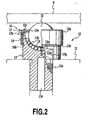
- Figure 2 is a partially broken cross-sectional view illustrating the internal structure of an application example of the ball transfer unit disclosed in the present invention, and assembled in the ball table shown in Figure 1 .
- Figure 1 show the appearance of the main parts of the ball table disclosed in this application example.
- Figure 2 shows the cross-sectional structure of a ball transfer unit assembled in the ball table.
- Female screw holes are formed at prescribed intervals on the surface of fixed disk 11 used as the support part in the present invention and made of SUS304, etc., treated by means of electroless nickel plating on the surface.
- a male [-form] screw part 13a that projects downwards from the central part of the main body 13 of a ball transfer unit 12 is screwed as a fastening part into each female [-form] screw hole.
- a positioning block not shown in the figure, is fixed on fixed disk 11. When the side end of a glass substrate W transported on fixed disk 11 is slid on fixed disk 11 and is pressed against the positioning block by an actuator, not shown in the figure, the position of glass substrate W can be corrected.
- Ball transfer unit 12 used in this application example has a cylindrical main body 13 having a seat surface 13b recessed in a semispherical shape formed in the center at the top, multiple small balls 14 rollingly in contact with the seat surface 13b of main body 13, a large ball 15 rollingly in contact with said multiple small balls 14, and cover 16, which is installed on main body 13 and holds large ball 15 and holds small balls 14 between said large ball 15 and the seat surface 13b of main body 13.
- PI polyimide
- Vespel registered trademark of DuPont
- Both small balls 14 and large ball 15 are mechanically ground to obtain a prescribed sphericity.
- the seat surface 13b of main body 13 is also mechanically ground to obtain a prescribed radius of curvature.
- most of small balls 14 have spot contact with both the seat surface 13b of main body 13 and the outer spherical surface of large ball 15 at the same time. In this way, the frictional resistance can be minimized when glass substrate W is moved from the state in which glass substrate W is carried on large ball 15.
- through hole 13c For through hole 13c that penetrates through main body 13 via the central part of male screw part 13a, one end opens on the seat surface 13b of main body 13, while the other end opens on the end surface of male screw part 13a.
- the opening end of through hole 13c on the side of seat surface 13b becomes small-diameter part 13d whose internal diameter is set to be smaller than the radius of small ball 14, so that the smooth rolling of small ball 14 along seat surface 13b will not be hindered.
- a chamfer 13e is formed at the opening end facing seat surface 13b. Because of said through hole 13c, when ball transfer unit 12 is used in, for example, a vacuum chamber, the air in ball transfer unit 12 can be evacuated quickly and reliably.
- the washing liquid flowing into ball transfer unit 12 can easily be discharged to the outside. Since one end of through hole 13c is opened on seat surface 13b to penetrate through main body 13, the other end of through hole 13c can be opened on the outer peripheral surface of main body 13.
- Said male screw part 13a is also made of PI and is integrally formed with main body 13. It is finished by means of mechanical processing.
- a female screw cylinder instead of male screw part 13a. In this case, the projection height of ball transfer unit 12 from fixed disk 11 can be finely adjusted more easily.
- Annular groove 13f in which securing part 16b formed over the entire inner circle [circumference] at the bottom (lower side in Figure 2 ) of cylindrical part 16a of cover 16 having a cup-shaped cross section can be secured, is formed on the outer peripheral surface of cylindrical main body 13. Since male screw part 13a is screwed into the female screw hole on fixed disk 11 to fix main body 13 on fixed disk 11, a pair of planar parts 13g having the so-called width across flats to be held by a spanner or other tool is also formed on the outer peripheral surface of the main part. In this application example, annular groove 13f is formed closer to the top of main body 13 (top in Figure 2 ) than said pair of planar parts 13g.
- Opening 16c from which the top part of large ball 15 is projected, is formed in the central part of cover 16.
- the internal diameter of said opening 16c is set to be smaller than the outer diameter of large ball 15.
- the internal diameter of the opening is set such that [the cover] is not in contact with large ball 15.
- the internal diameter of the cylindrical part 16a of cover 16 is set such that the cover is fit with a [certain] clearance with respect to the outer diameter of main body 13.
- the internal diameter of securing part 16b is set to be smaller than the outer diameter of main body 13.
- a tapered part 13h with a small tip whose outer diameter is smaller than the internal diameter of securing part 16b is formed at the top of the outer periphery of main body 13, with a notch 13i for ventilation with respect to space 17 encircled by said tapered part 13h and cover 16 being formed in a part on the top surface of main body 13.
- each ball transfer unit 12 from the surface of fixed disk 11 to the top of the ball transfer unit can be appropriately adjusted by inserting a shim (not shown in the figure) with an appropriate thickness between fixed disk 11 and main body 13 when fixing main body 13 on fixed disk 11.
- the entire ball transfer unit 12 is made of PI. It is also possible to use PAI, PBI, PCTFE, PEEK, PEI, PI, PPS, melamine resin, aromatic polyamide resin, aluminum oxide, zirconium oxide, or silicon nitride.
- ball transfer unit 12 when ball transfer unit 12 is used in pretreatment devices for liquid-crystal panel substrate glass, such as an exposure device, plasma dry etcher, vacuum chamber in sputtering device, or heating oven, or at a place exposed to chemicals or when using the ball transfer unit during the cutting of glass or laser repair for correction [of irregularities] after examination, in consideration of the properties of the ball transfer unit, attachment of foreign matter to the transported material, and the manufacturing cost, currently, the best choice is to use PI or PEEK or PBI to form the entire ball transfer unit 12.
- main body 13, small balls, 14, large ball 15, and cover 16 that constitute ball transfer unit 12 are all made of the same material, the washing operation with respect to foreign matter can be simplified. Also, when main body 13, small balls 14, and large ball 15 that are in contact with each other are made of the same material, there is a high possibility of minimizing the static frictional resistance. However, it has been confirmed that even if small balls 14 are made of a stainless steel, such as SUS304, SUS316, SUS420j2, SUS440C, or wet surface-treated (chemical grinding and surface washing) SUS304, SUS316, the metal powder will not attach to the transported material. Even if the metal powder attaches to said transported material, it can be washed off in a later step without any problems.
- a stainless steel such as SUS304, SUS316, SUS420j2, SUS440C, or wet surface-treated (chemical grinding and surface washing) SUS304, SUS316
- the ball table of the present invention can support plate-shaped transported material in a clean room, in which the attachment of metal powder or other foreign matter that is difficult to wash off later in the process should be prevented, and can easily adjust the position of the transported material.
Landscapes
- Engineering & Computer Science (AREA)
- Mechanical Engineering (AREA)
- General Engineering & Computer Science (AREA)
- Container, Conveyance, Adherence, Positioning, Of Wafer (AREA)
- Rollers For Roller Conveyors For Transfer (AREA)
- Rolling Contact Bearings (AREA)
- Ultra Sonic Daignosis Equipment (AREA)
- Float Valves (AREA)
Claims (9)
- Kugeltransporteinheit (12), die einen Hauptkörper (13) mit einer halbkugelförmig vertieften Sitzfläche (13b), mehrere kleine Kugeln (14) im Rollkontakt mit der Sitzfläche (13b) des Hauptkörpers (13), eine große Kugel (15) im Rollkontakt mit den mehreren kleinen Kugeln (14) und eine am Hauptkörper (13) angebrachte Abdeckung (16) zur Aufnahme der großen Kugel (15) und zur Aufnahme der kleinen Kugeln (14) zwischen der großen Kugel (15) und der Sitzfläche (13b) des Hauptkörpers (13) aufweist;
dadurch gekennzeichnet, daß
der oben erwähnte Hauptkörper (13) und die oben erwähnte große Kugel (15) aus irgendeinem Material bestehen, das unter PAI, PBI, PCTFE, PEEK, PEI, PI, PPS, Melaminharz, aromatischem Polyamidharz ausgewählt ist, und
die kleinen Kugeln (14) aus einem Material bestehen, das unter PAI, PBI, PCTFE, PEEK, PEI, PI, PPS, Melaminharzen, aromatischen Polyamidharzen, Aluminiumoxid, Zirconiumoxid, Siliciumnitrid und Edelstahl ausgewählt ist. - Kugeltransporteinheit (12) nach Anspruch 1, dadurch gekennzeichnet, daß die Rockwell-Härte HRR des oben erwähnten Hauptkörpers (13), der kleinen Kugeln (14) und der großen Kugel (15) mindestens gleich 75 ist.
- Kugeltransporteinheit (12) nach Anspruch 1, dadurch gekennzeichnet, daß die nach der Prüfnorm ASTM D648 gemessenen Wärmeverformungstemperaturen des oben erwähnten Hauptkörpers (13), der kleinen Kugeln (14) und der großen Kugel (15) alle mindestens gleich 120°C sind.
- Kugeltransporteinheit (12) nach einem der Ansprüche 1-3, dadurch gekennzeichnet, daß die Kugeltransporteinheit (12) aus einem einzelnen Material besteht.
- Kugeltransporteinheit (12) nach Anspruch 5, dadurch gekennzeichnet, daß das einzelne Material PBI, PEEK oder PI ist.
- Kugeltransporteinheit (12) nach einem der Ansprüche 1-5, dadurch gekennzeichnet, daß der oben erwähnte Hauptkörper (13) außerdem eine an seiner äußeren Umfangsfläche ausgebildete ringförmige Nut (13f) aufweist; die herkömmliche Abdeckung (16) einen zylinderförmigen Teil (16a), um die äußere Umfangsfläche des Hauptkörpers (13) paßgenau zu umschließen, und einen ringförmigen Sicherungsteil (16b) aufweist, der in radialer Richtung elastisch verformbar ist und am inneren Kreis am Boden des zylinderförmigen Teils (16a) ausgebildet ist um in die ringförmige Nut (13f) zu passen; und daß der Innendurchmesser des Sicherungsteils (16b) so festgesetzt ist, daß er kleiner ist als der Außendurchmesser des Hauptkörpers (13).
- Kugeltransporteinheit (12) nach einem der Ansprüche 1-6, dadurch gekennzeichnet, daß sie außerdem eine Durchgangsbohrung (13c) aufweist, die durch den Hauptkörper (13) hindurchgeht und deren eines Ende an der oben erwähnten Sitzfläche (13b) offen ist.
- Kugeltisch, der zur Unterstützung eines transportierten Materials verwendet wird, dadurch gekennzeichnet, daß er mehrere Kugeltransporteinheiten (12) nach einem der Ansprüche 1-5 und einen Auflageteil (11) aufweist, auf dem die Kugeltransporteinheiten (12) in vorgeschriebenen Abständen fixiert sind.
- Verwendung des Kugeltischs nach Anspruch 8 für den Transport eines Halbleiterwafers oder Glassubstrats für einen Flachbildschirm.
Applications Claiming Priority (2)
| Application Number | Priority Date | Filing Date | Title |
|---|---|---|---|
| JP2003270186 | 2003-07-01 | ||
| PCT/JP2004/009672 WO2005003001A1 (ja) | 2003-07-01 | 2004-07-01 | ボールトランスファユニットおよびボールテーブル |
Publications (3)
| Publication Number | Publication Date |
|---|---|
| EP1640295A1 EP1640295A1 (de) | 2006-03-29 |
| EP1640295A4 EP1640295A4 (de) | 2008-10-01 |
| EP1640295B1 true EP1640295B1 (de) | 2010-04-14 |
Family
ID=33562605
Family Applications (1)
| Application Number | Title | Priority Date | Filing Date |
|---|---|---|---|
| EP04747141A Revoked EP1640295B1 (de) | 2003-07-01 | 2004-07-01 | Kugelübertragungseinheit und kugeltisch |
Country Status (10)
| Country | Link |
|---|---|
| US (1) | US7370746B2 (de) |
| EP (1) | EP1640295B1 (de) |
| JP (1) | JPWO2005003001A1 (de) |
| KR (1) | KR100702081B1 (de) |
| CN (1) | CN1845863B (de) |
| AT (1) | ATE464255T1 (de) |
| DE (1) | DE602004026581D1 (de) |
| ES (1) | ES2344646T3 (de) |
| TW (1) | TW200524799A (de) |
| WO (1) | WO2005003001A1 (de) |
Families Citing this family (27)
| Publication number | Priority date | Publication date | Assignee | Title |
|---|---|---|---|---|
| JP5551888B2 (ja) * | 2009-04-14 | 2014-07-16 | 株式会社井口機工製作所 | フリーボールベアリング、ベアリング装置、支持テーブル、搬送設備、ターンテーブル |
| JP2010265095A (ja) * | 2009-05-15 | 2010-11-25 | Iguchi Kiko Seisakusho:Kk | ベアリングユニット、フリーボールベアリング、支持テーブル、搬送設備、ターンテーブル |
| KR101002615B1 (ko) * | 2010-03-23 | 2010-12-20 | 주식회사 코리아이엔지 | 볼트랜스퍼를 이용한 운반장치 |
| CN102147194B (zh) * | 2011-04-29 | 2012-08-08 | 湖州松华橡塑有限公司 | 一种烘房箱的工件推车 |
| US8864436B2 (en) * | 2011-12-06 | 2014-10-21 | Shenzhen China Star Optoelectronics Technology Co., Ltd. | Alignment device of cutting machine |
| US8529131B2 (en) * | 2011-12-06 | 2013-09-10 | Shenzhen China Star Optoelectronics Technology Co., Ltd. | Ball transfer unit |
| GB2531472B (en) * | 2013-02-20 | 2016-07-27 | Conveyor Units Ltd | Ball assembly and a method for manufacturing the same |
| CN104165720B (zh) * | 2013-05-17 | 2016-10-05 | 臻越自动化技术(上海)有限公司 | 支撑单元以及拉压力检测装置 |
| WO2015064582A1 (ja) | 2013-10-29 | 2015-05-07 | 本田技研工業株式会社 | 溶接ガン |
| CN103991667B (zh) * | 2014-06-04 | 2016-07-06 | 昆山宝锦激光拼焊有限公司 | 一种板材传送装置 |
| JP2016137733A (ja) | 2015-01-26 | 2016-08-04 | 三菱航空機株式会社 | フロアパネル装置 |
| CN104912921B (zh) * | 2015-05-30 | 2017-05-31 | 德清恒富机械有限公司 | 滚子轴承 |
| US9863839B2 (en) * | 2015-11-18 | 2018-01-09 | The Boeing Company | Positioner for electrodynamic shaker |
| TWM527411U (zh) * | 2016-05-06 | 2016-08-21 | Fivetech Technology Inc | 滾動裝置、滾動裝置包裝體及滾動模組 |
| CN206615780U (zh) * | 2017-03-24 | 2017-11-07 | 北京京东方显示技术有限公司 | 一种支撑传送机构和支撑传送装置 |
| CN107555174A (zh) * | 2017-09-27 | 2018-01-09 | 浙江云峰莫干山家居用品有限公司 | 气浮平台 |
| CN107585575A (zh) * | 2017-09-27 | 2018-01-16 | 浙江云峰莫干山家居用品有限公司 | 高效气浮装置 |
| JP2021536408A (ja) * | 2018-08-29 | 2021-12-27 | コーニング インコーポレイテッド | 物体支持装置および方法 |
| US11545380B2 (en) * | 2018-11-01 | 2023-01-03 | Brooks Automation Us Llc | Transport apparatus with linear bearing |
| JP2020189725A (ja) * | 2019-05-22 | 2020-11-26 | 島田テクノロジー株式会社 | ボールコンベア |
| CN110846943A (zh) * | 2019-12-19 | 2020-02-28 | 中铁宝桥集团有限公司 | 一种道岔滑床板以及转辙器 |
| CN110920653A (zh) * | 2019-12-20 | 2020-03-27 | 重庆艾博瑞威轨道交通设备有限公司 | 一种观光火车用万向球旁承 |
| KR102334200B1 (ko) * | 2020-06-03 | 2021-12-02 | 한국고요써모시스템(주) | 열처리 장치의 기판 반송 유닛 |
| USD1008792S1 (en) * | 2020-07-16 | 2023-12-26 | Willie Stewart | Ball wheel caster |
| CN113086491B (zh) * | 2021-03-27 | 2022-11-25 | 绍兴上虞亿欣球业有限公司 | 一种滚动装置及其包含滚动装置的传送装置、导向装置 |
| CN113800202B (zh) * | 2021-08-27 | 2023-07-21 | 山东灵犀院科技发展股份有限公司 | 一种滚动体 |
| CN113800201B (zh) * | 2021-08-27 | 2023-08-18 | 山东灵犀院科技发展股份有限公司 | 一种刮板 |
Family Cites Families (13)
| Publication number | Priority date | Publication date | Assignee | Title |
|---|---|---|---|---|
| JPS5016375Y2 (de) * | 1971-02-27 | 1975-05-21 | ||
| JPS58113491U (ja) * | 1982-01-26 | 1983-08-03 | 株式会社 共栄精工 | 作業台 |
| CN86206862U (zh) * | 1986-09-10 | 1987-07-22 | 安徽省蚌埠市燃料公司 | 可调轴承间隙的支撑托辊 |
| DE3805494A1 (de) * | 1988-02-22 | 1989-08-31 | Bavaria Cargo Tech | Foerderkugeleinheit |
| JP2641187B2 (ja) * | 1992-12-21 | 1997-08-13 | セントラル硝子株式会社 | ガラス板の位置決め装置 |
| JPH07164078A (ja) * | 1993-12-15 | 1995-06-27 | Murata Mach Ltd | 板材加工機のフリーボールベアリング |
| US5533604A (en) * | 1995-10-06 | 1996-07-09 | Brierton; Dennis M. | Ball transfer cube |
| JP4138909B2 (ja) * | 1997-06-30 | 2008-08-27 | 株式会社シンクロン | ボールローラー搬送システム |
| JP2000211717A (ja) * | 1999-01-20 | 2000-08-02 | Koyo Seiko Co Ltd | ガイド軸受 |
| JP2983985B1 (ja) * | 1999-01-28 | 1999-11-29 | エスアールエンジニアリング株式会社 | 物品可動支持装置 |
| JP2002240924A (ja) * | 2001-02-14 | 2002-08-28 | Takachiho Takeda | 搬送用ボールユニット |
| JP2004155531A (ja) * | 2002-11-05 | 2004-06-03 | Tanken Seal Seiko Co Ltd | 搬送用方向自在装置及び搬送用ベアリング |
| US6814212B1 (en) * | 2003-06-18 | 2004-11-09 | Frantz Manufacturing Company | Transport device for use with transport guides in conveyor systems |
-
2004
- 2004-07-01 CN CN2004800250887A patent/CN1845863B/zh not_active Expired - Fee Related
- 2004-07-01 US US10/561,568 patent/US7370746B2/en not_active Expired - Fee Related
- 2004-07-01 WO PCT/JP2004/009672 patent/WO2005003001A1/ja not_active Ceased
- 2004-07-01 TW TW093119948A patent/TW200524799A/zh not_active IP Right Cessation
- 2004-07-01 ES ES04747141T patent/ES2344646T3/es not_active Expired - Lifetime
- 2004-07-01 AT AT04747141T patent/ATE464255T1/de not_active IP Right Cessation
- 2004-07-01 EP EP04747141A patent/EP1640295B1/de not_active Revoked
- 2004-07-01 KR KR1020057025212A patent/KR100702081B1/ko not_active Expired - Lifetime
- 2004-07-01 JP JP2005511400A patent/JPWO2005003001A1/ja active Pending
- 2004-07-01 DE DE602004026581T patent/DE602004026581D1/de not_active Expired - Lifetime
Also Published As
| Publication number | Publication date |
|---|---|
| TWI339182B (de) | 2011-03-21 |
| EP1640295A4 (de) | 2008-10-01 |
| CN1845863A (zh) | 2006-10-11 |
| KR20060038404A (ko) | 2006-05-03 |
| EP1640295A1 (de) | 2006-03-29 |
| US7370746B2 (en) | 2008-05-13 |
| WO2005003001A1 (ja) | 2005-01-13 |
| US20070029158A1 (en) | 2007-02-08 |
| TW200524799A (en) | 2005-08-01 |
| JPWO2005003001A1 (ja) | 2006-08-10 |
| KR100702081B1 (ko) | 2007-04-02 |
| DE602004026581D1 (de) | 2010-05-27 |
| ES2344646T3 (es) | 2010-09-02 |
| ATE464255T1 (de) | 2010-04-15 |
| CN1845863B (zh) | 2011-03-09 |
Similar Documents
| Publication | Publication Date | Title |
|---|---|---|
| EP1640295B1 (de) | Kugelübertragungseinheit und kugeltisch | |
| US7692120B2 (en) | Transport robot and transport apparatus | |
| KR100625407B1 (ko) | 기판 지지부 | |
| KR101319951B1 (ko) | 프리 볼 베어링, 베어링 장치, 지지 테이블, 반송 설비, 및 턴테이블 | |
| US20030067180A1 (en) | End effector assembly | |
| CN1097689C (zh) | 开关装置 | |
| WO2011008805A2 (en) | Processing chamber with translating wear plate for lift pin | |
| KR20040035608A (ko) | 웨이퍼고정기구 | |
| WO2011009007A2 (en) | Improved lift pin guides | |
| JP5519099B2 (ja) | ボール継手を有するバルブドア | |
| US7845618B2 (en) | Valve door with ball coupling | |
| US9302358B2 (en) | Chamber elements and a method for placing a chamber at a load position | |
| US8550470B2 (en) | Positioning apparatus, a substrate processing apparatus and method for fixing a reference member | |
| JP5435577B2 (ja) | 基板収納容器 | |
| US20150206783A1 (en) | System amd method for substrate holding | |
| KR100756029B1 (ko) | 진공 압력 장비용 회전 및 왕복운동 밀폐장치 | |
| KR20230013938A (ko) | 회전축 밀폐장치 | |
| WO2023283587A1 (en) | Compliant guiding mechanism for mechanical actuator | |
| US7424393B2 (en) | Wafer inspection device | |
| CN221097428U (zh) | 化学气相沉积设备的密封装置以及化学气相沉积设备 | |
| KR20220144143A (ko) | 탑 엔츄리형 메탈 시이트 볼밸브 | |
| US8449196B2 (en) | Fluid-tight rotation-guiding device | |
| CN114743906B (zh) | 动力传递装置及半导体制造设备 | |
| CN121653612A (zh) | 半导体加热盘的装配方法和半导体工艺腔室 | |
| CN116968052A (zh) | 一种旋转式机械臂和硅片加工设备 |
Legal Events
| Date | Code | Title | Description |
|---|---|---|---|
| PUAI | Public reference made under article 153(3) epc to a published international application that has entered the european phase |
Free format text: ORIGINAL CODE: 0009012 |
|
| 17P | Request for examination filed |
Effective date: 20060105 |
|
| AK | Designated contracting states |
Kind code of ref document: A1 Designated state(s): AT BE BG CH CY CZ DE DK EE ES FI FR GB GR HU IE IT LI LU MC NL PL PT RO SE SI SK TR |
|
| DAX | Request for extension of the european patent (deleted) | ||
| A4 | Supplementary search report drawn up and despatched |
Effective date: 20080828 |
|
| 17Q | First examination report despatched |
Effective date: 20090220 |
|
| GRAP | Despatch of communication of intention to grant a patent |
Free format text: ORIGINAL CODE: EPIDOSNIGR1 |
|
| RIN1 | Information on inventor provided before grant (corrected) |
Inventor name: IGUCHI, KAORU Inventor name: TAKAHASHI, MASAKAZU |
|
| GRAS | Grant fee paid |
Free format text: ORIGINAL CODE: EPIDOSNIGR3 |
|
| GRAA | (expected) grant |
Free format text: ORIGINAL CODE: 0009210 |
|
| AK | Designated contracting states |
Kind code of ref document: B1 Designated state(s): AT BE BG CH CY CZ DE DK EE ES FI FR GB GR HU IE IT LI LU MC NL PL PT RO SE SI SK TR |
|
| REG | Reference to a national code |
Ref country code: GB Ref legal event code: FG4D |
|
| REG | Reference to a national code |
Ref country code: CH Ref legal event code: EP |
|
| REG | Reference to a national code |
Ref country code: IE Ref legal event code: FG4D |
|
| REF | Corresponds to: |
Ref document number: 602004026581 Country of ref document: DE Date of ref document: 20100527 Kind code of ref document: P |
|
| REG | Reference to a national code |
Ref country code: NL Ref legal event code: T3 |
|
| REG | Reference to a national code |
Ref country code: ES Ref legal event code: FG2A Ref document number: 2344646 Country of ref document: ES Kind code of ref document: T3 |
|
| REG | Reference to a national code |
Ref country code: GR Ref legal event code: EP Ref document number: 20100401667 Country of ref document: GR |
|
| PG25 | Lapsed in a contracting state [announced via postgrant information from national office to epo] |
Ref country code: SE Free format text: LAPSE BECAUSE OF FAILURE TO SUBMIT A TRANSLATION OF THE DESCRIPTION OR TO PAY THE FEE WITHIN THE PRESCRIBED TIME-LIMIT Effective date: 20100414 |
|
| PG25 | Lapsed in a contracting state [announced via postgrant information from national office to epo] |
Ref country code: SI Free format text: LAPSE BECAUSE OF FAILURE TO SUBMIT A TRANSLATION OF THE DESCRIPTION OR TO PAY THE FEE WITHIN THE PRESCRIBED TIME-LIMIT Effective date: 20100414 Ref country code: FI Free format text: LAPSE BECAUSE OF FAILURE TO SUBMIT A TRANSLATION OF THE DESCRIPTION OR TO PAY THE FEE WITHIN THE PRESCRIBED TIME-LIMIT Effective date: 20100414 Ref country code: AT Free format text: LAPSE BECAUSE OF FAILURE TO SUBMIT A TRANSLATION OF THE DESCRIPTION OR TO PAY THE FEE WITHIN THE PRESCRIBED TIME-LIMIT Effective date: 20100414 |
|
| PG25 | Lapsed in a contracting state [announced via postgrant information from national office to epo] |
Ref country code: PL Free format text: LAPSE BECAUSE OF FAILURE TO SUBMIT A TRANSLATION OF THE DESCRIPTION OR TO PAY THE FEE WITHIN THE PRESCRIBED TIME-LIMIT Effective date: 20100414 Ref country code: CY Free format text: LAPSE BECAUSE OF FAILURE TO SUBMIT A TRANSLATION OF THE DESCRIPTION OR TO PAY THE FEE WITHIN THE PRESCRIBED TIME-LIMIT Effective date: 20100428 |
|
| PLBI | Opposition filed |
Free format text: ORIGINAL CODE: 0009260 |
|
| PG25 | Lapsed in a contracting state [announced via postgrant information from national office to epo] |
Ref country code: DK Free format text: LAPSE BECAUSE OF FAILURE TO SUBMIT A TRANSLATION OF THE DESCRIPTION OR TO PAY THE FEE WITHIN THE PRESCRIBED TIME-LIMIT Effective date: 20100414 Ref country code: PT Free format text: LAPSE BECAUSE OF FAILURE TO SUBMIT A TRANSLATION OF THE DESCRIPTION OR TO PAY THE FEE WITHIN THE PRESCRIBED TIME-LIMIT Effective date: 20100816 Ref country code: EE Free format text: LAPSE BECAUSE OF FAILURE TO SUBMIT A TRANSLATION OF THE DESCRIPTION OR TO PAY THE FEE WITHIN THE PRESCRIBED TIME-LIMIT Effective date: 20100414 |
|
| PLAX | Notice of opposition and request to file observation + time limit sent |
Free format text: ORIGINAL CODE: EPIDOSNOBS2 |
|
| REG | Reference to a national code |
Ref country code: CH Ref legal event code: NV Representative=s name: SERVOPATENT GMBH |
|
| 26 | Opposition filed |
Opponent name: GROZ-BECKERT KG Effective date: 20110112 |
|
| PG25 | Lapsed in a contracting state [announced via postgrant information from national office to epo] |
Ref country code: SK Free format text: LAPSE BECAUSE OF FAILURE TO SUBMIT A TRANSLATION OF THE DESCRIPTION OR TO PAY THE FEE WITHIN THE PRESCRIBED TIME-LIMIT Effective date: 20100414 Ref country code: MC Free format text: LAPSE BECAUSE OF NON-PAYMENT OF DUE FEES Effective date: 20100731 Ref country code: RO Free format text: LAPSE BECAUSE OF FAILURE TO SUBMIT A TRANSLATION OF THE DESCRIPTION OR TO PAY THE FEE WITHIN THE PRESCRIBED TIME-LIMIT Effective date: 20100414 |
|
| GBPC | Gb: european patent ceased through non-payment of renewal fee |
Effective date: 20100714 |
|
| PG25 | Lapsed in a contracting state [announced via postgrant information from national office to epo] |
Ref country code: BG Free format text: LAPSE BECAUSE OF NON-PAYMENT OF DUE FEES Effective date: 20100831 |
|
| PLAF | Information modified related to communication of a notice of opposition and request to file observations + time limit |
Free format text: ORIGINAL CODE: EPIDOSCOBS2 |
|
| PG25 | Lapsed in a contracting state [announced via postgrant information from national office to epo] |
Ref country code: GR Free format text: LAPSE BECAUSE OF NON-PAYMENT OF DUE FEES Effective date: 20110202 |
|
| PG25 | Lapsed in a contracting state [announced via postgrant information from national office to epo] |
Ref country code: GB Free format text: LAPSE BECAUSE OF NON-PAYMENT OF DUE FEES Effective date: 20100714 Ref country code: CZ Free format text: LAPSE BECAUSE OF NON-PAYMENT OF DUE FEES Effective date: 20100701 Ref country code: IE Free format text: LAPSE BECAUSE OF NON-PAYMENT OF DUE FEES Effective date: 20100701 |
|
| PGFP | Annual fee paid to national office [announced via postgrant information from national office to epo] |
Ref country code: TR Payment date: 20110613 Year of fee payment: 8 |
|
| PLBB | Reply of patent proprietor to notice(s) of opposition received |
Free format text: ORIGINAL CODE: EPIDOSNOBS3 |
|
| PGFP | Annual fee paid to national office [announced via postgrant information from national office to epo] |
Ref country code: CH Payment date: 20110712 Year of fee payment: 8 |
|
| PG25 | Lapsed in a contracting state [announced via postgrant information from national office to epo] |
Ref country code: HU Free format text: LAPSE BECAUSE OF FAILURE TO SUBMIT A TRANSLATION OF THE DESCRIPTION OR TO PAY THE FEE WITHIN THE PRESCRIBED TIME-LIMIT Effective date: 20101015 Ref country code: LU Free format text: LAPSE BECAUSE OF NON-PAYMENT OF DUE FEES Effective date: 20100701 |
|
| PGFP | Annual fee paid to national office [announced via postgrant information from national office to epo] |
Ref country code: DE Payment date: 20120627 Year of fee payment: 9 Ref country code: ES Payment date: 20120824 Year of fee payment: 9 Ref country code: BE Payment date: 20120713 Year of fee payment: 9 Ref country code: IT Payment date: 20120712 Year of fee payment: 9 Ref country code: FR Payment date: 20120719 Year of fee payment: 9 |
|
| REG | Reference to a national code |
Ref country code: DE Ref legal event code: R103 Ref document number: 602004026581 Country of ref document: DE Ref country code: DE Ref legal event code: R064 Ref document number: 602004026581 Country of ref document: DE |
|
| RDAF | Communication despatched that patent is revoked |
Free format text: ORIGINAL CODE: EPIDOSNREV1 |
|
| PGFP | Annual fee paid to national office [announced via postgrant information from national office to epo] |
Ref country code: NL Payment date: 20120710 Year of fee payment: 9 |
|
| RDAG | Patent revoked |
Free format text: ORIGINAL CODE: 0009271 |
|
| STAA | Information on the status of an ep patent application or granted ep patent |
Free format text: STATUS: PATENT REVOKED |
|
| REG | Reference to a national code |
Ref country code: CH Ref legal event code: PL |
|
| 27W | Patent revoked |
Effective date: 20130109 |
|
| PG25 | Lapsed in a contracting state [announced via postgrant information from national office to epo] |
Ref country code: CH Free format text: LAPSE BECAUSE OF THE APPLICANT RENOUNCES Effective date: 20100414 Ref country code: BG Free format text: LAPSE BECAUSE OF NON-PAYMENT OF DUE FEES Effective date: 20110630 Ref country code: LI Free format text: LAPSE BECAUSE OF THE APPLICANT RENOUNCES Effective date: 20100414 |
|
| REG | Reference to a national code |
Ref country code: DE Ref legal event code: R107 Ref document number: 602004026581 Country of ref document: DE Effective date: 20130801 |
|
| REG | Reference to a national code |
Ref country code: GR Ref legal event code: ML Ref document number: 20100401667 Country of ref document: GR Effective date: 20110202 |