EP1640431A1 - Phosphore mgal sb 2 /sb o sb 4 /sb de type spinel dope au metal de transition, appareil laser comprenant ce phosphore, et procede d'elaboration correspondant - Google Patents
Phosphore mgal sb 2 /sb o sb 4 /sb de type spinel dope au metal de transition, appareil laser comprenant ce phosphore, et procede d'elaboration correspondant Download PDFInfo
- Publication number
- EP1640431A1 EP1640431A1 EP04733138A EP04733138A EP1640431A1 EP 1640431 A1 EP1640431 A1 EP 1640431A1 EP 04733138 A EP04733138 A EP 04733138A EP 04733138 A EP04733138 A EP 04733138A EP 1640431 A1 EP1640431 A1 EP 1640431A1
- Authority
- EP
- European Patent Office
- Prior art keywords
- laser
- transition metal
- fluorescent material
- raw material
- spinel type
- Prior art date
- Legal status (The legal status is an assumption and is not a legal conclusion. Google has not performed a legal analysis and makes no representation as to the accuracy of the status listed.)
- Withdrawn
Links
Images


Classifications
-
- C—CHEMISTRY; METALLURGY
- C09—DYES; PAINTS; POLISHES; NATURAL RESINS; ADHESIVES; COMPOSITIONS NOT OTHERWISE PROVIDED FOR; APPLICATIONS OF MATERIALS NOT OTHERWISE PROVIDED FOR
- C09K—MATERIALS FOR MISCELLANEOUS APPLICATIONS, NOT PROVIDED FOR ELSEWHERE
- C09K11/00—Luminescent materials, e.g. electroluminescent or chemiluminescent
- C09K11/08—Luminescent materials, e.g. electroluminescent or chemiluminescent containing inorganic luminescent materials
- C09K11/64—Luminescent materials, e.g. electroluminescent or chemiluminescent containing inorganic luminescent materials containing aluminium
- C09K11/641—Chalcogenides
- C09K11/643—Chalcogenides with alkaline earth metals
-
- C—CHEMISTRY; METALLURGY
- C30—CRYSTAL GROWTH
- C30B—SINGLE-CRYSTAL GROWTH; UNIDIRECTIONAL SOLIDIFICATION OF EUTECTIC MATERIAL OR UNIDIRECTIONAL DEMIXING OF EUTECTOID MATERIAL; REFINING BY ZONE-MELTING OF MATERIAL; PRODUCTION OF A HOMOGENEOUS POLYCRYSTALLINE MATERIAL WITH DEFINED STRUCTURE; SINGLE CRYSTALS OR HOMOGENEOUS POLYCRYSTALLINE MATERIAL WITH DEFINED STRUCTURE; AFTER-TREATMENT OF SINGLE CRYSTALS OR A HOMOGENEOUS POLYCRYSTALLINE MATERIAL WITH DEFINED STRUCTURE; APPARATUS THEREFOR
- C30B13/00—Single-crystal growth by zone-melting; Refining by zone-melting
- C30B13/16—Heating of the molten zone
- C30B13/22—Heating of the molten zone by irradiation or electric discharge
- C30B13/24—Heating of the molten zone by irradiation or electric discharge using electromagnetic waves
-
- C—CHEMISTRY; METALLURGY
- C30—CRYSTAL GROWTH
- C30B—SINGLE-CRYSTAL GROWTH; UNIDIRECTIONAL SOLIDIFICATION OF EUTECTIC MATERIAL OR UNIDIRECTIONAL DEMIXING OF EUTECTOID MATERIAL; REFINING BY ZONE-MELTING OF MATERIAL; PRODUCTION OF A HOMOGENEOUS POLYCRYSTALLINE MATERIAL WITH DEFINED STRUCTURE; SINGLE CRYSTALS OR HOMOGENEOUS POLYCRYSTALLINE MATERIAL WITH DEFINED STRUCTURE; AFTER-TREATMENT OF SINGLE CRYSTALS OR A HOMOGENEOUS POLYCRYSTALLINE MATERIAL WITH DEFINED STRUCTURE; APPARATUS THEREFOR
- C30B29/00—Single crystals or homogeneous polycrystalline material with defined structure characterised by the material or by their shape
- C30B29/10—Inorganic compounds or compositions
- C30B29/16—Oxides
- C30B29/22—Complex oxides
- C30B29/26—Complex oxides with formula BMe2O4, wherein B is Mg, Ni, Co, Al, Zn, or Cd and Me is Fe, Ga, Sc, Cr, Co, or Al
-
- H—ELECTRICITY
- H01—ELECTRIC ELEMENTS
- H01S—DEVICES USING THE PROCESS OF LIGHT AMPLIFICATION BY STIMULATED EMISSION OF RADIATION [LASER] TO AMPLIFY OR GENERATE LIGHT; DEVICES USING STIMULATED EMISSION OF ELECTROMAGNETIC RADIATION IN WAVE RANGES OTHER THAN OPTICAL
- H01S3/00—Lasers, i.e. devices using stimulated emission of electromagnetic radiation in the infrared, visible or ultraviolet wave range
- H01S3/14—Lasers, i.e. devices using stimulated emission of electromagnetic radiation in the infrared, visible or ultraviolet wave range characterised by the material used as the active medium
- H01S3/16—Solid materials
Definitions
- the present invention relates to a transition metal doped spinel type MgAl 2 O 4 fluorescent material, i. e., a fluorescent material having a crystalline matrix made of MgAl 2 O 4 single crystal with a spinel crystallographic structure and doped with a transition metal. It also relates to a transition metal doped MgAl 2 O 4 laser apparatus, i. e., a laser apparatus using such a fluorescent material. The invention further relates to a method of making a transition metal-doped MgAl 2 O 4 fluorescent material.
- Fluorescent materials are known to be indispensable to a variety of color displays. Among them, there are also some classes of fluorescent materials doped with emission centers in an insulator crystalline matrix. Because of a broad emission spectrum, such a fluorescent material when used as a laser medium for a laser apparatus of external resonator type, is capable of laser oscillations over various wavelengths and when used as a laser medium for a source of an ultrashort light pulse, it is possible to make its time width extremely short. And, because of the facts that its fluorescent emission efficiency is high and that the higher of melting point, its matrix crystal the higher is the output of a laser using it, active researches on fluorescent materials of this type whose melting point of matrix crystals are high, have been conducted.
- a ruby laser and a Ti-doped sapphire laser both of which have a corundum type crystallographic structure
- their laser medium is a fluorescent material of which the matrix crystal is of Al 2 O 3 and the emission centers are of a transition metal.
- Excellent properties of these lasers owe much to the high melting point of their matrix crystal (i. e., a melting point of 2050 °C) as well as to its high crystal perfection which allows it to form an energy level that is high in terms of emission efficiency and optimum for laser oscillations when doped with a transition metal.
- a fluorescent material can be made having a MgAl 2 O 4 matrix crystal of spinel type crystallographic structure that has a melting point (i. e., 2135 °C) higher than that of the Al 2 O 3 crystal and that is yet excellent in crystal perfection, it would make it possible to provide a laser that is yet higher in output.
- Document 1 (L. E. Bausa, I. Vergara and J. Garcia-sole: J. Appl. Phys. 68 (2), 15 July 1990, p. 736) describes a Ti doped spinel type MgAl 2 O 4 fluorescent material having Ti doped at 0.05 atomic %, made by the Verneuil method.
- the fluorescent material has absorption peaks at 490 nm and 790 nm, besides band edge absorption.
- the fluorescent material has an emission peak of 465 nm by band edge excitation (266 nm) and an emission peak of 805 nm by excitation at 532 nm.
- the 490 nm absorption, the 465 nm emission and the 805 emission of the fluorescent material are according to d - d transitions of d - electrons of Ti 3+ located at B site of the spinel crystal in ligand field of 6 oxygens.
- the 790 nm absorption is regarded as by Ti 4+ - Fe 2+ pair.
- the absorptions and emissions of this fluorescent material are mainly caused by d - d transitions most of which are electric dipole forbidden transitions and its emission efficiency must therefore be low.
- the first object of the present invention is to provide a transition metal doped spinel type MgAl 2 O 4 fluorescent material that is capable of laser oscillation.
- a second object of the present invention is to provide a transition metal doped MgAl 2 O 4 laser apparatus, i. e., a laser apparatus using such a fluorescent material.
- a third object of the present invention is to provide a method of making a transition metal doped MgAl 2 O 4 fluorescent material.
- a t ransition metal doped spinel type MgAl 2 O 4 fluorescent material in accordance with the present invention is characterized in that it is made by growing a single-crystal from a source material rod in a selected gaseous atmosphere wherein the source material rod is formed from a mixed raw material of an Al raw material and a Mg raw material added thereto in an amount together with a transition metal raw material so that the amount of Mg exceeds that of Al by a few percents in terms of molar ratio.
- the said selected gaseous atmosphere may be an oxidizing or inert gas, and the said source material rod can be single-crystallized, preferably using floating zone melting.
- the fluorescent material according to the present invention is essentially free from vacancies of Mg or oxygen, and indeed the material undoped with a transition metal, namely the spinel type MgAl 2 O 4 matrix crystal itself is high in crystalline perfection to an extent that it has no absorption peak for light of a wavelength ranging from 300 nm to 900 nm.
- the fluorescent material according to the present invention may be characterized in that it uses the above-mentioned matrix crystal, and the said transition metal is Ti and the said fluorescent material has a composition expressed by chemical formula MgAl 2-x Ti x O 4 where 0.003 ⁇ x ⁇ 0.01 and that it has no absorption peak except for its band edge absorption for light wavelengths of 200 nm to 900 nm and it is capable of light emission having a peak at 490 nm by its band edge excitation.
- Ti may exist as Ti 4+ at a B site in the spinel type MgAl 2 O 4 crystal, and the light emission may occur when the electron of an electron-hole pair generated by band edge excitation is captured by a Ti 4+ to form an intermediate energy state and recombines with a hole captured by an O in the vicinity of the Ti 4+ .
- the light emission may also occur conversely when a hole is captured by an O in the vicinity of a Ti 4+ to form an intermediate energy state and recombines with an electron in the vicinity of the Ti 4+ . Since this emission process is not by electric dipole forbidden transition but by charge transfer transition which is one or two order higher in transition probability than the electric dipole forbidden transition in the d-d transition, a fluorescent material provided here is having a high emission efficiency rendering it capable of laser oscillation.
- the fluorescent material according to the present invention may also be characterized in that it uses the above-mentioned matrix crystal, and the said transition metal is Mn and the said fluorescent material has a composition expressed by chemical formula Mg 1-x Mn x Al 2 O 4 where 0.003 ⁇ x ⁇ 0.01 and in a wavelength range of 200nm to 900nm it has its band edge absorption and absorption with a peak at 450 nm of which intensity increases as the amount of doped Mn is increased, and it has light emission having a peak at 520 nm by its band edge excitation or excitation at 450 nm and light emission having a peak at 650 nm by its band edge excitation.
- the emission at 650 nm is caused by Mn existing as Mn 2+ at an A site in the spinel type MgAl 2 O 4 crystal.
- the electron of an electron-hole pair generated by band edge excitation is captured by a Mn 2+ to form an intermediate energy state and recombines with a hole captured by an O in the vicinity of the Mn 2+ .
- the emission may also occur conversely so that a hole is captured by an O in the vicinity of a Mn 2+ to form an intermediate energy state and recombines with an electron in the vicinity of the Mn 2+ .
- the fluorescent material provided here Since this emission process is not by electric dipole forbidden transition but by charge transfer transition which is one or two order higher in transition probability than the electric dipole forbidden transition in the d - d transition and also since the emission at 520 nm is caused by both the d - d and charge transfer transitions, the fluorescent material provided here has high emission efficiency rendering it capable of laser oscillation.
- the fluorescent material according to the present invention may also be characterized in that the said transition metal doped in the matrix crystal, is V and the said fluorescent material has a composition expressed by chemical formula MgAl 2-x V x O 4 where 0.001 ⁇ x ⁇ 0.01 and that it has no absorption peak except for its band edge absorption for a wavelength range of 200 nm to 900 nm and it is capable of white color light emission over wavelengths of 450 nm to 750 nm by its band edge excitation.
- the V doped spinel type MgAl 2 O 4 fluorescent material is a fluorescent material which like the Ti and Mn doped fluorescent materials described above, is high in emission efficiency so as to be capable of laser oscillation.
- transition metal doped spinel type MgAl 2 O 4 laser apparatus characterized in that it has a laser medium made of a transition metal doped spinel type MgAl 2 O 4 fluorescent material discussed above.
- the laser apparatus may be characterized in that the laser medium is made of a said Ti doped spinel type MgAl 2 O 4 fluorescent material and that the said laser medium is side-pumped with a fourth harmonic of a Nd: YAG laser (having a wavelength of 266 nm), a fourth harmonic of a Nd: YLF (having a wavelength of 262 nm) or a fourth harmonic of a Nd: YAP laser (having a wavelength of 269 nm) and is caused to resonate with an external laser resonator to produce blue or green color laser oscillation light utilizing light emission having the peak at 490 nm of the said fluorescent material.
- a fourth harmonic of a Nd: YAG laser having a wavelength of 266 nm
- a fourth harmonic of a Nd: YLF having a wavelength of 262 nm
- a fourth harmonic of a Nd: YAP laser having a wavelength of 269 nm
- the laser apparatus may also be characterized in that the said laser medium is a said Mn doped spinel type MgAl 2 O 4 fluorescent material and that the said laser medium is side-pumped with a fourth harmonic of a Nd: YAG laser (having a wavelength of 266 nm), a fourth harmonic of a Nd: YLF (having a wavelength of 262 nm) or a fourth harmonic of a Nd: YAP laser (having a wavelength of 269 nm) and is caused to resonate with an external laser resonator to produce blue or green and/or red color laser oscillation utilizing light emission having the peak or peaks at 520 nm and/or 650 nm of the said fluorescent material.
- a fourth harmonic of a Nd: YAG laser having a wavelength of 266 nm
- a fourth harmonic of a Nd: YLF having a wavelength of 262 nm
- a fourth harmonic of a Nd: YAP laser having a wavelength of
- the laser apparatus may also be characterized in that two Ti doped spinel type MgAl 2 O 4 fluorescent materials and a Mn doped spinel type MgAl 2 O 4 fluorescent material are disposed in series in an external laser resonator and these three fluorescent materials are side-pumped with a fourth harmonic of a Nd: YAG laser (having a wavelength of 266 nm), a fourth harmonic of a Nd: YLF (having a wavelength of 262 nm) or a fourth harmonic of a Nd: YAP laser (having a wavelength of 269 nm) to produce blue and green color laser oscillations, respectively, from the two Ti doped spinel type MgAl 2 O 4 fluorescent materials and red color laser oscillation from the Mn doped spinel type MgAl 2 O 4 fluorescent material, simultaneously.
- This setup provides a laser with the three primary colors.
- the laser apparatus may also be characterized in that said Ti doped spinel type MgAl 2 O 4 fluorescent material and two said Mn doped spinel type MgAl 2 O 4 fluorescent materials are disposed in series in an external laser resonator and these three fluorescent materials are side-pumped with a fourth harmonic of a Nd: YAG laser (having a wavelength of 266 nm), a fourth harmonic of a Nd: YLF (having a wavelength of 262 nm) or a fourth harmonic of a Nd: YAP laser (having a wavelength of 269 nm) to produce blue or green color laser oscillation from the Ti doped spinel type MgAl 2 O 4 fluorescent material and blue or green and red color laser oscillations, respectively, from the Mn doped spinel type MgAl 2 O 4 fluorescent materials, simultaneously.
- This setup provides a laser with the three primary colors, too.
- the laser apparatus may also be characterized in that said Ti doped spinel type MgAl 2 O 4 fluorescent material and a Mn doped spinel type MgAl 2 O 4 fluorescent material are disposed in series in an external laser resonator and these two fluorescent materials are side-pumped with a fourth harmonic of a Nd: YAG laser (having a wavelength of 266 nm), a fourth harmonic of a Nd: YLF (having a wavelength of 262 nm) or a fourth harmonic of a Nd: YAP laser (having a wavelength of 269 nm) to produce blue or green color laser oscillation from the said Ti doped spinel type MgAl 2 O 4 fluorescent material and blue or green and red color laser oscillations from the said Mn doped spinel type MgAl 2 O 4 fluorescent material, simultaneously.
- This setup provides a laser with the three primary colors, too.
- a method of making a transition metal doped spinel type MgAl 2 O 4 fluorescent material characterized in that it comprises: preparing a mixed raw material of an Al raw material and a Mg raw material added thereto in an amount together with a transition metal raw material so that the amount of Mg exceeds that of Al by a few percents in terms of molar ratio, shaping the mixed raw material under pressure to form a source material rod, and growing a single-crystal from the source material rod in a selected gaseous atmosphere by floating zone melting method.
- the said selected gaseous atmosphere may be an oxidizing or inert gas.
- Adopting this method it is possible to obtain a spinel type MgAl 2 O 4 matrix crystal that is essentially free from vacancies of Mg or oxygen and is high in crystalline perfection to an extent, for example, that the material without a transition metal, namely the matrix crystal has no absorption peak for light wavelengths of 300 nm to 900 nm.
- the said Al raw material is Al 2 O 3
- the said Mg raw material is MgO and the said transition metal raw material is TiO 2 and the raw material TiO 2 is added to the raw material Al 2 O 3 at a proportion in a range of 0.003 to 0.01 in terms of molar ratio
- the said Al raw material is Al 2 O 3
- the said Mg raw material is MgO and the said transition metal raw material is MnO 2 and the raw material MnO 2 is added to the raw material MgO at a proportion in a range of 0.003 to 0.01 in terms of molar ratio
- the said Al raw material is Al 2 O 3
- the said Mg raw material is MgO and the said transition metal raw material is a V metal and the V metal raw material is added to the raw material Al 2 O 3 at a proportion in a range of 0.001 to 0.01 in terms of molar ratio
- a transition metal doped spinel type MgAl 2 O 4 fluorescent material may also be made by mixing together a source material Al 2 O 3 , a source material MgO and a transition metal raw material to form a mixture thereof; shaping under pressure, and sintering the mixture to form a sintered body; and growing epitaxially on a single-crystal substrate a single-crystal thin film of transition metal doped spinel type MgAl 2 O 4 fluorescent material by laser ablation using the said sintered body as a target in an O 2 gas.
- a method of making a fluorescent material in accordance with the present invention comprises the step of mixing an aluminum oxide raw material, a magnesium oxide raw material and a transition metal raw material together, the step of shaping the mixture under pressure to form a source material rod, and a melt growth step of placing the source material rod on a seed rod of the source material in a floating zone melting furnace and growing single-crystal by a floating zone melting method in a gaseous atmosphere.
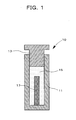
- Fig. 1 is a conceptual view illustrating a diagrammatic cross section of a pseudo-hydrostatic forming apparatus.
- the pseudo-hydrostatic forming apparatus designated by reference character 10
- the pseudo-hydrostatic forming apparatus comprises a cylinder 11 filled with water 15, a piston 13 and an oil hydraulic press (not shown).
- a source material mixture 17 formed into a columnar shape e. g., by being packed into a tube type balloon (with a diameter of about 6 mm and a length of about 250 mm)
- the oil hydraulic press exerts a load of, e. g., 300 kg/cm 2
- the source material rod has a length of, e. g., 50 to 100 mm while a seed rod is of a length of, e. g., 20 to 50 mm.
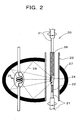
- Fig. 2 is a conceptual view illustrating such a floating zone melting furnace.
- the floating zone melting furnace designated by reference character 20
- the floating zone melting furnace comprises a fused silica tube 23 in which to maintain a gaseous atmosphere therein, argon or oxygen gas or both can be introduced from a gas supply system such as a cylinder (not shown).
- a gas supply system such as a cylinder (not shown).
- It also includes a pair of shafts 21 and 21 which hold between them a seed rod 22 lying lower and a source material rod 26 lying upper in the fused silica tube 23 and which are jointly rotatable and movable vertically.
- a spheroidal bifocal mirror 27 an infrared convergent heating source 25 such as a xenon lamp disposed at one focal position of the bifocal mirror 27, and a window for observation (not shown).
- the floating zone melting furnace 20 is associated with a computer (not shown) for controlling the rotary and vertical movements of the shafts 21 and 21 and their heating temperature and rates of temperature rise and fall.
- an end of the seed rod 22 held by one of the shafts 21 and an end of the source material rod 26 held by the other shaft 21 are positioned to lie at the other or second focal position of the spheroidal mirror 27 so that by controlling vertical movement of the shafts 21 and 21 allows a desired growth.
- infrared rays 29 are drawn in order to show the condensation of light at the second focal position of the spheroidal mirror 27.
- a MgAl 2 O 4 single crystal having a spinel type crystallographic structure and doped with a transition metal at its adequate positions in matrix crystal can be made in a short period of time and moreover in a size of, e. g., a diameter of 5 mm and a length of 100 mm or more. Furthermore, without the need to use a crucible to hold a melt, it is possible to make such a single crystal that is free of contamination by impurities and that has a same concentration for the transition metal as in the source material.
- the method of making such a sintered target comprises a mixing step of mixing an aluminum oxide raw material, a magnesium oxide raw material and a transition metal raw material together, a compression molding step of forming the mixed source material to prepare a target shaped body and a sintering step of heating the formed body in a given gaseous atmosphere to make the sintered target.
- Fig. 3 is a conceptual cross sectional view illustrating such a die set.
- a mould or die set 30 is shown comprising a metal cylinder 33 loaded with a mixture or mixed source material 34, a pair of an upper and a lower pistons 31 and 31 and a pressing unit (not shown) that applies pressure to the pistons 31 and 31 upward and downward. Pressing is cold pressing.
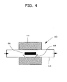
- Fig. 4 is a conceptual view diagrammatically illustrated cross section of an electric furnace heating system that constitutes the sintering apparatus.
- the electric furnace heating system designated by reference character 40, comprises an electric furnace of cylinder type 41, an aluminum core tube 43 that withstands high temperature, a gas supply subsystem (not shown) for supplying a gas into the core tube 43 and a vacuum pumping subsystem (not shown) that permits pumping up to high vacuum.
- the electric furnace heating system 40 also controls its degree of vacuum, heating temperature and rising and falling rates of temperature.
- the vacuum pumping subsystem may use, for example, a combination of oil diffusion and rotary pumps.
- a space formed of the pistons 31 and the metal cylinder 33 is filled with a source material mixture 34, and when a load, e. g., of 200 kg/cm 2 , is applied to the pistons 31 and 31 from both sides to compress and mold the source material mixture 34, a formed body 46 is produced, having a diameter of 20 mm and a thickness of 5 mm, for example.
- a load e. g., of 200 kg/cm 2
- the compression-molded formed body 46 is placed on an alumina ceramic boat 44 and then placed in the core tube 43.
- the core tube 43 is then supplied with a selected gas while evacuated as indicated by the arrows in Fig. 4 while sintering proceeds. In this way, a sintered body is formed under a selected temporal profile of temperature in the electric furnace 41.
- a sintered body made in such a method is shaped as desired shape in the stage of pressure molding and thus can have a shape suitable for its intended use.
- Fig. 5 is a conceptual view of a laser ablation apparatus.
- the laser ablation apparatus indicated by reference character 50, comprises a vacuum chamber 51, a substrate retaining and heating unit 53 that holds a substrate 52 and controls its temperature in the vacuum chamber 51, and a gas supply unit 54 for introducing a gas into the vacuum chamber 51. It also includes a target 55 whose material is to be vapor-deposited on the substrate 52 and a laser light source for laser ablation 57 disposed outside of the vacuum chamber 51 for irradiating the target 55 with a pulsed laser light 56 to vaporize the target material therefrom.
- the apparatus 50 further includes a RHEED (reflection high-energy electron diffraction) unit 58 made of an electron gun 58a and an electron beam detector 58b for analyzing a structure of the material vapor-deposited on the substrate 52, which makes it possible to control the film thickness of the vapor-deposited material (from the target 55) in an atomic layer unit. Using this unit allows obtaining a vapor-deposited thin film that has a same composition as that of the target material.
- RHEED reflection high-energy electron diffraction
- a thin film crystalline fluorescent material according to the present invention may be made by using this apparatus holding a single crystal substrate 52 at a selected temperature while laser-ablating material from the target for vapor deposition on the substrate 52, the target being a sintered body made by sintering a mixture of an aluminum oxide material, a magnesium oxide material and a transition metal material which are put together in selected concentrations.
- An aluminum oxide (Al 2 O 3 ) material and a magnesium oxide (MgO) material were mixed together and a mixture thereof was compression-molded in a pressure forming apparatus as shown in Fig. 1 to prepare a rod of source material, which was placed in a floating zone melting furnace as shown in Fig. 2 to single-crystallize the source material by the floating zone melting method in gaseous atmosphere.
- a resultant MgAl 2 O 4 matrix crystal was irradiated with a ray of ultraviolet light having a peak at 360 nm and its emission spectrum was observed.
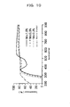
- Fig. 6 is a graph comparing the emission spectra of MgAl 2 O 4 matrix crystals grown with the different conditions, when they were excited with a band edge excitation light of 275 nm.
- the abscissa axis represents the light wavelength for fluorescence and the ordinate axis represents the emission intensity in an arbitrary scale.
- Curves (1) to (4) in the graph indicate the emission spectra of specimens which were grown by floating zone melting from a source material rod made of the aluminum oxide (Al 2 O 3 ) and magnesium oxide (MgO) materials mixed together so that they are present in an equal amount in terms of molar ratio, in (1) a gaseous atmosphere of mixed Ar and H 2 gases (with H 2 at a volume proportion of 2.4 %), (2) an atmosphere of O 2+ ion gas, (3) a gaseous atmosphere of O 2 gas and (4) an atmosphere of Ar gas, respectively.
- a source material rod made of the aluminum oxide (Al 2 O 3 ) and magnesium oxide (MgO) materials mixed together so that they are present in an equal amount in terms of molar ratio
- Curve (5) indicates the emission spectrum of a specimen which was grown by floating zone melting from a source material rod made of the aluminum oxide (Al 2 O 3 ) and magnesium oxide (MgO) materials mixed together so that the amount of MgO exceeds that of Al 2 O 3 by 1 % in terms of molar ratio in an atmosphere of O 2 gas.
- Al 2 O 3 aluminum oxide
- MgO magnesium oxide
- a mixed source material is made by mixing an Al raw material with a Mg raw material so that an amount of Mg exceeds that of Al in terms of molar ratio a few percents, by pressure-molding the mixed source material into a source material rod and by single-crystallizing the source material rod by the floating zone melting method in an oxygen or Ar gas.
- Source material rods were prepared from mixed source materials containing an aluminum oxide (Al 2 O 3 ) material and a magnesium oxide (MgO) material in a proportion such that an amount of MgO exceeds that of Al 2 O 3 by 1 % in terms of molar ratio, and containing with various amounts of TiO 2 as the transition metal material added thereto, and the source material rods were single-crystallized in an Ar or O 2 gas by the floating zone melting method to form fluorescent materials, and their properties were measured.
- Al 2 O 3 aluminum oxide
- MgO magnesium oxide
- Fig. 7 is a graph showing transmittance characteristics of a matrix crystal and Ti doped fluorescent materials according to the present invention.
- the abscissa and ordinate axes represent the light wavelength and transmittance, respectively.
- the dashed dotted line indicates the transmittance of the matrix crystal while the dotted line, the dashed line and the solid line indicate the transmittances of the fluorescent materials doped with Ti at 0.1 %, 0.3 % and 1 % in terms of molar ratio to Al 2 , respectively.
- the matrix crystal has no absorption peak in a wavelength range of 200 nm to 900 nm except for the band edge absorption and has property needed for an optical crystal. It is also seen that a fluorescent material doped with Ti has no absorption peak in a wavelength range of 200 nm to 900 nm except for the band edge absorption. It is further seen that the transmittance rises as the Ti doping amount is increased.
- Fig. 8 is a graph showing spectra of light emissions by band edge excitation light of Ti doped fluorescent materials according to the present invention.
- the abscissa axis represents the emission wavelength and the ordinate axis represents the emission intensity in an arbitrary scale.
- Curve (1), curve (2), curve (3) and curve (4) indicate the emission spectra of the fluorescent materials doped with Ti at 0.3 %, 0.5 %, 1 % and 0.1 % in terms of molar ratio to Al 2 , respectively.
- the band edge excitation light used was an ultraviolet ray of a wavelength around 275 nm where the emission efficiency is the highest. Note here that the flattened peak of the solid curve (1) is due to a limit of measurement by the measuring device.
- these fluorescent materials are fluorescent materials which by the band edge excitation produce light emissions having a peak at 490 nm and a full width at half minimum of about 130 nm and that their fluorescence intensity becomes the highest when the Ti concentration ranges between 0.3 % and 1 %.
- Fig. 9 is a graph showing time resolved spectra of a light emission spectrum having a peak at 490 nm of a Ti doped fluorescent material.
- the abscissa axis represents the emission spectral wavelength and the ordinate axis represents the emission intensity in an arbitrary scale.
- a fluorescent material doped with Ti at 0.3 % was irradiated with ultrashort light pulses having a center wavelength of 275 nm to measure changes of the 490 nm emission spectrum with time.
- Respective spectra at successive delays of time after the irradiation are shown, which are designated by different type lines, and these delays of time are indicated in the graph.
- the emission spectrum has a time constant of about 9 microseconds. And, from the fact that the time constant is in the order of microseconds, it is seen that the emission mechanism is not due to the d-d transition by d electron of Ti, because the d-d transition that is an electric dipole forbidden transition requires time constant to be in the order of milliseconds.
- the light emission occurs when the electron of an electron-hole pair generated by band edge excitation is captured by a Ti 4+ to form an intermediate energy state and recombines with a hole captured by an O in the vicinity of the Ti 4+ .
- the light emission may also occur conversely when a hole is captured by an O in the vicinity of a Ti 4+ to form an intermediate energy state and recombines with an electron in the vicinity of the Ti 4+ .
- Source material rods were prepared from mixed source materials containing an aluminum oxide (Al 2 O 3 ) material and an magnesium oxide (MgO) material in a proportion such that an amount of MgO exceeds that of Al 2 O 3 by 1 % in terms of molar ratio with various amounts of MnO 2 as the transition metal material added thereto, and the source material rods were single-crystallized in an Ar or O 2 gas by the floating zone melting method to form fluorescent materials, and their properties were measured.
- Al 2 O 3 aluminum oxide
- MgO magnesium oxide
- Fig. 10 is a graph showing transmittance characteristics of Mn doped fluorescent materials according to the present invention.
- the abscissa and ordinate axes represent the light wavelength and transmittance, respectively.
- the dashed dotted line indicates the transmittance of the matrix crystal while the dotted line, the dashed line and the solid line indicate the transmittances of the fluorescent materials doped with Mn at 0.3 %, 0.5 % and 1 % in terms of molar ratio to Mg, respectively. From the graph, it is seen that the fluorescent materials doped with Mn at 0.3 % or less has no absorption peak over a wavelength range of 200 nm to 900 nm except for the band edge absorption.
- Fig. 11 is a graph showing spectra of light emissions by 450 nm excitation light of Mn doped fluorescent materials according to the present invention.
- the abscissa axis represents the light wavelength and the ordinate axis represents the light intensity.
- the dotted line, the dashed line and the solid line indicate the emission spectra of the fluorescent materials doped with Mn at 0.3 %, 0.5 % and 1 % in terms of molar ratio to Mg, respectively.
- the 450 nm excitation produces light emissions having a peak at 520 nm and a full width at half maximum of 30 nm. Note here that though not shown, it has been confirmed that an emission peak at 520 nm is produced by band edge excitation, too, with a quantum efficiency of the same degree.
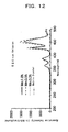
- Fig. 12 is a graph showing excitation spectra of emission spectra having a peak at 520 nm of Mn doped fluorescent materials according to the present invention.
- the abscissa axis represents the wavelength of excitation light and the ordinate axis represents the intensity of excitation light in an arbitrary scale.
- the dotted line, the dashed line and the solid line indicate the excitation spectra of fluorescent materials doped with Mn at 0.3 %, 0.5 % and 1 % by molar ratio to Mg. From the graph it is seen that there exist two excitation peaks at around 450 nm and two excitation peaks at 400 nm or less.
- Fig. 13 is a graph showing time resolved spectra of an emission spectrum having a peak at 520 nm of a Mn doped fluorescent material according to the present invention.
- the abscissa axis represents the wavelength of an emission spectrum and the ordinate axis represents the emission intensity in an arbitrary scale.
- the fluorescent material doped with Mn at 0.3 % was irradiated with ultrashort light pulses having a central wavelength of 520 nm, and changes of the emission spectrum of 520 nm with time were measured.
- Respective spectra at successive delays of time after the irradiation are shown, which are designated by different line types, and these delays of time are indicated in the graph.
- the emission spectrum has a time constant as long as about 1 millisecond. From the four excitation spectra in Fig. 12 and the time constant from Fig. 13, it is seen that the emission mechanism is based on d-d transitions in the ligand field of 4 oxygens, by d electrons of Mn 2+ ions positioned at A sites in the spinel type crystal. Since most of d-d transitions are electric dipole forbidden transitions, the time constant is long. Though not shown, it has also been confirmed that the emission when by band edge excitation has a time constant in the order of microseconds, indicating that charge transfer transitions are brought about in this case.
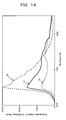
- Fig. 14 is a graph showing spectra of light emissions by band edge excitation of Mn doped fluorescent materials according to the present invention.
- the abscissa axis represents the emission wavelength and the ordinate axis represents the emission intensity in an arbitrary scale.
- curve (1), curve (2) and curve (3) indicate the emission spectra of the fluorescent materials doped with Mn at 0.3 %, 0.5 % and 1 % in terms of molar ratio to Mg, respectively.
- the band edge excitation light source used was a source of an ultraviolet ray of a wavelength around 260 nm where the emission efficiency is the highest.
- these fluorescent materials produce by the band edge excitation light emissions whose spectra having a peak at 650 nm and a full width at half maximum of about 70 nm and their fluorescence intensity is the highest when the Mn concentration ranges between 0.3 % and 1 %.
- Fig. 15 is a graph showing time resolved spectra of an emission spectrum having a peak at 650 nm of a Mn doped fluorescent material according to the present invention.
- the abscissa axis represents the emission spectral wavelength and the ordinate axis represents the emission intensity in an arbitrary scale.
- the fluorescent material doped with Mn at 0.3 % was irradiated with ultrashort light pulses having a wavelength of 260 nm, and changes of the emission spectrum of 650 nm with time were measured.
- Respective spectra at successive delays of time after the irradiation are shown and identified with different types of lines with indications of these delays of time in the graph for the spectra. From this graph, it is seen that the emission spectrum having a peak at 650 nm has a time constant in the order of several tens microseconds.
- the emission at 650 nm occurs by Mn existing as Mn 2+ at an A site in the spinel type MgAl 2 O 4 crystal, the electron of an electron-hole pair generated by band edge excitation is captured by a Mn 2+ to form an intermediate energy state and recombines with a hole captured by an O in the vicinity of the Mn 2+ .
- Source material rods were prepared from mixed source materials containing an aluminum oxide (Al 2 O 3 ) material and a magnesium oxide (MgO) material in a proportion such that an amount of MgO exceeds that of Al 2 O 3 by 1 % in terms of molar ratio with various amounts of a V metal as the transition metal material added thereto and the source material rods were single-crystallized in an Ar or O 2 gas by the floating zone melting method to form fluorescent materials, and their properties were measured.
- Al 2 O 3 aluminum oxide
- MgO magnesium oxide
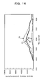
- Fig. 16 is a graph showing emission spectra of light emissions by band edge excitation of V doped fluorescent materials according to the present invention.
- the abscissa axis represents the fluorescence wavelength and the ordinate axis represents the fluorescence intensity in an arbitrary scale.
- curve (1), curve (2), curve (3) and curve (4) indicate the emission spectra of the fluorescent materials doped with V at 0.1 %, 0.3 %, 1 % and 3 % in terms of molar ratio to Al 2 , respectively.
- the excitation source used was a source of an ultraviolet ray of a wavelength around 330 nm where the emission efficiency is the highest. From the graph, it is seen that these fluorescent materials produce white fluorescent emissions over a wavelength range from 450 nm to 750 nm and that their fluorescence intensity is the highest when the V concentration ranges between 0.1 % and 1 %.
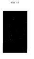
- a thin film single crystal fluorescent material was epitaxially grown on a SrTiO 3 (100) substrate by laser ablation in an O 2 gas and its properties were measured.
- Fig. 17 is a picture showing a RHEED (reflection high-energy electron diffraction) pattern of the thin film single crystal fluorescent material of MgAl 2-x Ti x O 4 grown epitaxially on the SrTiO 3 (100) substrate. From this diffraction pattern, it is seen that the thin film single crystal fluorescent material of the present invention is a single crystalline thin film.
- RHEED reflection high-energy electron diffraction
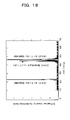
- Fig. 18 is a chart showing an X-ray diffraction pattern of the thin film single crystal fluorescent material of MgAl 2-x Ti x O 4 . From the chart it is seen that the thin film formed here is a Ti doped spinel type MgAl 2 O 4 single crystalline thin film.
- Fig. 19 is a photograph showing fluorescence emitted from the thin film single crystal fluorescent material of MgAl 2-x Ti x O 4 when it is excited by an electron beam energized with an accelerating voltage of 20 keV and applied from the rear surface of the substrate. From the picture, it is seen that strong blue emission is obtained.
- the laser apparatus in accordance with the present invention has its laser medium made of a Ti, Mn, or V doped spinel type MgAl 2 O 4 fluorescent material according to the present invention as mentioned above.
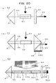
- Fig. 20 shows embodiments in setup of the laser apparatus according to the present invention.
- a laser apparatus 60 of the present invention includes a resonator comprising a servo prism 61 and a semi-transparent mirror 62 and a laser medium 63 disposed in the resonator and made of a spinel type MgAl 2 O 4 fluorescent material doped with Ti, Mn or V whereby irradiating the laser medium laterally with excitation light 64 produces resonant light 65 and causes laser oscillation light 66 to be emitted.
- a laser apparatus 70 of the present invention has the laser medium 63 of spinel type MgAl 2 O 4 fluorescent material doped with Ti, Mn or V disposed in a resonator made of the prism 61 and a prism 67 and includes a broadband prism 68 laterally coupled to the prism 67 whereby irradiating the laser medium 63 laterally with excitation light 64 produces resonant lights 65 and causes laser oscillation light 66 to be emitted laterally from the broadband prism 68.
- the bottom surface of the broadband prism 68 has a reflection film 68a of 100% reflectance.
- a laser apparatus 80 of the present invention has laser media 63a and 63b made of Ti doped spinel type MgAl 2 O 4 fluorescent material and a laser medium 63c made of Mn doped spinel type MgAl 2 O 4 fluorescent material disposed in series in the resonator made of the prism 61 and the semi-transparent mirror 62 whereby irradiating the laser media 63a, 63b and 63c laterally with excitation light 64 produces resonant lights 65 and causes laser oscillation lights 66a, 66b and 66c to be emitted.
- the fourth harmonic (having a wavelength of 266 nm) of a Nd: YAG laser, the fourth harmonic (having a wavelength of 262 nm) of a Nd: YLF or the fourth harmonic (having a wavelength of 269 nm) of a Nd: YAP laser, as its source.
- the use of a Ti doped spinel type MgAl 2 O 4 fluorescent material for the laser medium allows blue or green colored laser oscillation light to be obtained by utilizing light emission having a peak at 490 nm of this fluorescent material.
- the use of a Mn doped spinel type MgAl 2 O 4 fluorescent material for the laser medium allows red colored laser oscillation light to be obtained by utilizing light emission having a peak at 650 nm of this fluorescent material.
- the use of a V doped spinel type MgAl 2 O 4 fluorescent material for the laser medium allows white colored laser oscillation light to be obtained by utilizing broad light emissions from 400 nm to 800 nm of this fluorescent material.
- blue and green colored laser oscillation light emissions can be obtained respectively from the two laser media of Ti doped spinel type MgAl 2 O 4 fluorescent material 63a and 63b and red colored laser light emission from the laser medium of Mn doped spinel type MgAl 2 O 4 fluorescent material 63c, concurrently; hence there result laser light emissions of the three primary colors.
- a laser medium of Ti doped spinel type MgAl 2 O 4 fluorescent material and two laser media of Mn doped spinel type MgAl 2 O 4 fluorescent material may be disposed in series in an external laser resonator and these three laser media may be side-pumped with the fourth harmonic (having a wavelength of 266 nm) of a Nd: YAG laser, the fourth harmonic (having a wavelength of 262 nm) of a Nd: YLF, or the fourth harmonic (having a wavelength of 269 nm) of a Nd: YAP laser, making it possible to produce blue or green emission from the laser medium of Ti doped spinel type MgAl 2 O 4 fluorescent material, and green or blue and red emissions, respectively, from the two laser media of Mn doped spinel type MgAl 2 O 4 fluorescent material, simultaneously, and thus to obtain a laser of the three primary colors.
- a first laser medium of Ti doped spinel type MgAl 2 O 4 fluorescent material and a second laser medium of Mn doped spinel type MgAl 2 O 4 fluorescent material may be disposed in series in an external laser resonator and these two laser media of fluorescent materials may be side-pumped with the fourth harmonic (having a wavelength of 266 nm) of a Nd: YAG laser, the fourth harmonic (having a wavelength of 262 nm) of a Nd: YLF, or the fourth harmonic (having a wavelength of 269 nm) of a Nd: YAP laser, making it possible to produce blue or green emission from the Ti doped spinel type MgAl 2 O 4 fluorescent material, and green or blue and red emissions from the Mn doped spinel type MgAl 2 O 4 fluorescent material, simultaneously, and thus to obtain a laser of the three primary colors.
- the prism was composed of fused quartz, the mirror had a reflectance of 98 %, the laser medium had a length of about 2 cm and the excitation light had an intensity of 10 MW/cm 2 .
- Fig. 21 is a photograph showing oscillations of such a Ti doped spinel type MgAl 2 O 4 fluorescent material laser apparatus of the present invention, in which Fig. 21 (a) shows blue color laser oscillations obtained using a Ti doped spinel type MgAl 2 O 4 fluorescent material as the laser medium and Fig. 21(b) is a near-field pattern of the blue color oscillations shown in Fig. 21(a).
- Fig. 22 shows orange (red) color laser oscillations of such a Mn doped spinel type MgAl 2 O 4 fluorescent material laser apparatus of the present invention.
- a transition metal doped spinel type MgAl 2 O 4 fluorescent material can be used as a laser medium of a laser of external resonator type and can be used in a laser oscillation apparatus for emissions with various wavelengths in a visible light range. Also, when used as a laser medium in a light source of ultrashort light pulses, it can be used in an ultrashort light pulse laser apparatus having a wavelength center in a visible light region. Further, it is useful to use it as a fluorescent material for many kind of color displays as well.
Landscapes
- Chemical & Material Sciences (AREA)
- Engineering & Computer Science (AREA)
- Organic Chemistry (AREA)
- Materials Engineering (AREA)
- Electromagnetism (AREA)
- Physics & Mathematics (AREA)
- Crystallography & Structural Chemistry (AREA)
- Metallurgy (AREA)
- Inorganic Chemistry (AREA)
- Plasma & Fusion (AREA)
- Optics & Photonics (AREA)
- Lasers (AREA)
- Luminescent Compositions (AREA)
Applications Claiming Priority (2)
| Application Number | Priority Date | Filing Date | Title |
|---|---|---|---|
| JP2003136537 | 2003-05-14 | ||
| PCT/JP2004/006852 WO2004101711A1 (fr) | 2003-05-14 | 2004-05-14 | Phosphore mgal2o4 de type spinel dope au metal de transition, appareil laser comprenant ce phosphore, et procede d'elaboration correspondant |
Publications (2)
| Publication Number | Publication Date |
|---|---|
| EP1640431A1 true EP1640431A1 (fr) | 2006-03-29 |
| EP1640431A4 EP1640431A4 (fr) | 2008-11-05 |
Family
ID=33447230
Family Applications (1)
| Application Number | Title | Priority Date | Filing Date |
|---|---|---|---|
| EP04733138A Withdrawn EP1640431A4 (fr) | 2003-05-14 | 2004-05-14 | Matiére fluorescente de structure spinelle doppée avec des métaux de transition |
Country Status (3)
| Country | Link |
|---|---|
| EP (1) | EP1640431A4 (fr) |
| JP (1) | JPWO2004101711A1 (fr) |
| WO (1) | WO2004101711A1 (fr) |
Cited By (2)
| Publication number | Priority date | Publication date | Assignee | Title |
|---|---|---|---|---|
| KR101606222B1 (ko) | 2011-06-14 | 2016-03-24 | 서울대학교산학협력단 | 백색 발광을 구현하는 MgAl2O4 스피넬 형광체 및 그 제조 방법 |
| WO2016135057A1 (fr) * | 2015-02-27 | 2016-09-01 | Leuchtstoffwerk Breitungen Gmbh | Céramique composite à luminophore et procédé pour la produire |
Families Citing this family (5)
| Publication number | Priority date | Publication date | Assignee | Title |
|---|---|---|---|---|
| US8540173B2 (en) | 2010-02-10 | 2013-09-24 | Imra America, Inc. | Production of fine particles of functional ceramic by using pulsed laser |
| JP6501288B2 (ja) * | 2014-07-07 | 2019-04-17 | 国立大学法人宇都宮大学 | マンガンドープスピネル型赤色蛍光体及びその製造方法 |
| CN117000223B (zh) * | 2022-04-29 | 2026-02-10 | 中国石油化工股份有限公司 | 镁铝复合氧化物载体及其制备方法和甲烷干重整催化剂及其应用 |
| CN116855750B (zh) * | 2023-05-22 | 2024-06-04 | 山东大学 | 一种高光产额、超快闪烁衰减、低成本Cs3Cu2I5:Mn单晶闪烁体及其制备与应用 |
| CN119286521B (zh) * | 2024-12-10 | 2025-05-30 | 浙江理工大学 | 一种稀土长余辉光控发光材料及其制备方法 |
Family Cites Families (4)
| Publication number | Priority date | Publication date | Assignee | Title |
|---|---|---|---|---|
| JP3334182B2 (ja) * | 1992-09-10 | 2002-10-15 | 東ソー株式会社 | レーザー結晶及びその製造法 |
| US5802083A (en) * | 1995-12-11 | 1998-09-01 | Milton Birnbaum | Saturable absorber Q-switches for 2-μm lasers |
| JP4329270B2 (ja) * | 2000-08-02 | 2009-09-09 | ソニー株式会社 | 発光体の製造方法 |
| JP2002194349A (ja) * | 2000-12-27 | 2002-07-10 | National Institute Of Advanced Industrial & Technology | 応力発光材料およびその製造方法 |
-
2004
- 2004-05-14 EP EP04733138A patent/EP1640431A4/fr not_active Withdrawn
- 2004-05-14 WO PCT/JP2004/006852 patent/WO2004101711A1/fr not_active Ceased
- 2004-05-14 JP JP2005506252A patent/JPWO2004101711A1/ja active Pending
Cited By (2)
| Publication number | Priority date | Publication date | Assignee | Title |
|---|---|---|---|---|
| KR101606222B1 (ko) | 2011-06-14 | 2016-03-24 | 서울대학교산학협력단 | 백색 발광을 구현하는 MgAl2O4 스피넬 형광체 및 그 제조 방법 |
| WO2016135057A1 (fr) * | 2015-02-27 | 2016-09-01 | Leuchtstoffwerk Breitungen Gmbh | Céramique composite à luminophore et procédé pour la produire |
Also Published As
| Publication number | Publication date |
|---|---|
| JPWO2004101711A1 (ja) | 2006-07-13 |
| WO2004101711A1 (fr) | 2004-11-25 |
| EP1640431A4 (fr) | 2008-11-05 |
Similar Documents
| Publication | Publication Date | Title |
|---|---|---|
| US5164041A (en) | Method of growing rare earth doped orthosilicates(ln2-xrexsio5) | |
| US5140604A (en) | Mixed strontium and lanthanide oxides and a laser using monocrystals of these oxides | |
| Sarukura et al. | Czochralski growth of oxides and fluorides | |
| Kim et al. | Growth and optical properties of Pr, Yb-codoped KY3F10 fluoride single crystals for up-conversion visible luminescence | |
| Gao et al. | Effect of Yb3+ concentration on microstructure and optical properties of Yb: SrF2 transparent ceramics | |
| EP1640431A1 (fr) | Phosphore mgal sb 2 /sb o sb 4 /sb de type spinel dope au metal de transition, appareil laser comprenant ce phosphore, et procede d'elaboration correspondant | |
| Pracka et al. | The Czochralski growth of SrLaGa3O7 single crystals and their optical and lasing properties | |
| US3866142A (en) | Doped beryllium lanthanate crystals | |
| Brasse et al. | Liquid Phase Epitaxy growth, structure and spectroscopy of highly-doped 20 at.% Yb3+: LiYF4 thin films | |
| US20060243197A1 (en) | Transition metal doped spinel type mgal2o4 fluorescent material and laser apparatus using, and method of making, such fluorescent material | |
| Chen et al. | Vertical Bridgman growth and optical properties of Pr3+-doped NaY (MoO4) 2 crystal | |
| US3769230A (en) | Calcium fluoride-rare earth fluoride fluorescent compound useful as alaser crystal | |
| Cassouret et al. | Growth, structure and optical characterization of new Pr3+-doped LaGaGe2O7 and LaGa0. 6Al0. 4Ge2O7 single crystals | |
| US4853354A (en) | Mixed lanthanum-magnesium aluminates and lasers using monocrystals of these aluminates | |
| US20220200231A1 (en) | Rare-earth-doped alumina-oxide laser gain media | |
| Gredin et al. | Optical properties of fluoride transparent ceramics | |
| Jouini et al. | Ti-doped MgAl2O4 spinel single crystals grown by the micro-pulling-down method for laser application: Growth and strong visible blue emission | |
| JP3412726B2 (ja) | 光学材料の製造方法 | |
| JP7228793B2 (ja) | 波長変換デバイス | |
| RU2428778C2 (ru) | Оптический лазерный материал и способ его получения | |
| Yen | Preparation of single crystal fibers | |
| US3983051A (en) | Doped beryllium lanthanate crystals | |
| EP0536999B1 (fr) | Procédé de production de monocristaux de titanate de barium | |
| Chang et al. | Fabrication of laser materials by laser-heated pedestal growth | |
| Liu et al. | Growth and property characterization of large-sized Nd: CNGG crystals for high-energy chirped pulse amplification systems |
Legal Events
| Date | Code | Title | Description |
|---|---|---|---|
| PUAI | Public reference made under article 153(3) epc to a published international application that has entered the european phase |
Free format text: ORIGINAL CODE: 0009012 |
|
| 17P | Request for examination filed |
Effective date: 20051129 |
|
| AK | Designated contracting states |
Kind code of ref document: A1 Designated state(s): DE FR GB |
|
| RTI1 | Title (correction) |
Free format text: TRANSITION METAL DOPED SPINEL TYPE MGAL 2 04 PHOSPHOR, LASER APPARATUS INCLUDING THE SAME AND PROCESS FOR PRODUCING THE PHOSPHOR |
|
| RTI1 | Title (correction) |
Free format text: TRANSITION METAL DOPED SPINEL TYPE FLUORESCENT MATERIAL |
|
| DAX | Request for extension of the european patent (deleted) | ||
| RBV | Designated contracting states (corrected) |
Designated state(s): DE FR GB |
|
| RIN1 | Information on inventor provided before grant (corrected) |
Inventor name: KATO, KIYOSHI Inventor name: MURAOKA, TOSHIHARU Inventor name: TERASHIMA, TAKAHITO Inventor name: TOMITA, AYANA Inventor name: YAMANAKA, AKIO Inventor name: TAKANO, MIKIO Inventor name: KAWABE, YUTAKA Inventor name: HANAMURA, EIICHI Inventor name: SATO, TOKUSHI |
|
| A4 | Supplementary search report drawn up and despatched |
Effective date: 20081009 |
|
| STAA | Information on the status of an ep patent application or granted ep patent |
Free format text: STATUS: THE APPLICATION IS DEEMED TO BE WITHDRAWN |
|
| 18D | Application deemed to be withdrawn |
Effective date: 20090108 |