EP1640461A2 - Goulotte de distribution, notamment pour des hauts fourneaux - Google Patents
Goulotte de distribution, notamment pour des hauts fourneaux Download PDFInfo
- Publication number
- EP1640461A2 EP1640461A2 EP05108730A EP05108730A EP1640461A2 EP 1640461 A2 EP1640461 A2 EP 1640461A2 EP 05108730 A EP05108730 A EP 05108730A EP 05108730 A EP05108730 A EP 05108730A EP 1640461 A2 EP1640461 A2 EP 1640461A2
- Authority
- EP
- European Patent Office
- Prior art keywords
- chute
- feed material
- box
- shell
- load bearing
- Prior art date
- Legal status (The legal status is an assumption and is not a legal conclusion. Google has not performed a legal analysis and makes no representation as to the accuracy of the status listed.)
- Withdrawn
Links
Images


Classifications
-
- F—MECHANICAL ENGINEERING; LIGHTING; HEATING; WEAPONS; BLASTING
- F27—FURNACES; KILNS; OVENS; RETORTS
- F27D—DETAILS OR ACCESSORIES OF FURNACES, KILNS, OVENS OR RETORTS, IN SO FAR AS THEY ARE OF KINDS OCCURRING IN MORE THAN ONE KIND OF FURNACE
- F27D3/00—Charging; Discharging; Manipulation of charge
- F27D3/0033—Charging; Discharging; Manipulation of charge charging of particulate material
-
- C—CHEMISTRY; METALLURGY
- C21—METALLURGY OF IRON
- C21B—MANUFACTURE OF IRON OR STEEL
- C21B7/00—Blast furnaces
- C21B7/18—Bell-and-hopper arrangements
- C21B7/20—Bell-and-hopper arrangements with appliances for distributing the burden
-
- F—MECHANICAL ENGINEERING; LIGHTING; HEATING; WEAPONS; BLASTING
- F27—FURNACES; KILNS; OVENS; RETORTS
- F27B—FURNACES, KILNS, OVENS OR RETORTS IN GENERAL; OPEN SINTERING OR LIKE APPARATUS
- F27B1/00—Shaft or like vertical or substantially vertical furnaces
- F27B1/10—Details, accessories or equipment specially adapted for furnaces of these types
- F27B1/20—Arrangements of devices for charging
-
- F—MECHANICAL ENGINEERING; LIGHTING; HEATING; WEAPONS; BLASTING
- F27—FURNACES; KILNS; OVENS; RETORTS
- F27D—DETAILS OR ACCESSORIES OF FURNACES, KILNS, OVENS OR RETORTS, IN SO FAR AS THEY ARE OF KINDS OCCURRING IN MORE THAN ONE KIND OF FURNACE
- F27D3/00—Charging; Discharging; Manipulation of charge
- F27D3/10—Charging directly from hoppers or shoots
Definitions
- the present invention relates to a rotating chute for distribution of the charge, particularly for blast furnaces, to be used in furnaces devoid of a bell and hopper feeding system.
- chutes for feeding of blast furnaces which are adapted to enable a suitable wall distribution of the charge in the blast furnace.
- These types of chutes are susceptible of being supported in a sloping configuration by means of suitable mechanical structures capable of setting in rotation the chute itself through 360°.
- the chute generally has a semicircular or rectangular structure in section and is defined by a first impact surface receiving the charge falling down from top and by a second sliding surface consecutive to the preceding one, enabling the charge to slide and be directed against the blast furnace wall at a suitable speed.
- the suspended chute driven in rotation receives the charge consisting of pellets, iron ore and scraps on a surface thereof and directs it at a suitable speed towards the furnace wall so as to conveniently and homogeneously feed said furnace.
- a constant chute efficiency is of the greatest importance for good operation of the blast furnace.
- the rotating chutes presently built in the world consist of a series of individual elements (divided into structural elements and wear-resistant elements) connected to each other by a series of bolts. Said bolts, submitted to continuous thermal shocks, tend to break and the individual elements are subjected to deformation giving rise to the following problems:
- said coating Due to its deformation, said coating can become curved within the chute, thus altering the charge distribution in the furnace in addition to extending the dismantling time of the latter.
- rotating chutes which have suitable emerging transverse metal plates in the material-receiving region, which metal plates are such disposed as to retain part of the material itself; therefore, the subsequent charge impacts on the previously retained material and not directly on the chute structure. In this way, an increase in the strength of this region occurs through exploitation of the "material against material” principle.
- the present invention aims at substantially obviating the above mentioned drawbacks.
- Additional aims of the invention consist in improving the chute resistance in particular to temperatures and mechanical shocks at the rear portion of the chute itself, by a new planning of the closing structure; it is also an object of the invention to improve the structural resistance of the whole apparatus by suitably combining protection elements and stiffening elements with each other.
- a rotating chute for distribution of feed material in particular for blast furnaces has been generally identified by reference numeral 1.
- the rotating distributing chute for blast furnaces being the object of the invention is intended for use in installations in which a bell and hopper feeding system is not present; in more detail the same is hanging, by grip means 9, from a suitably sized mechanical structure that is able to set the chute itself in rotation through 360° so that the charge necessary for operation of the blast furnace can be distributed within the latter in the most suitable, homogeneous and regular manner.
- the grip means 9 is defined by tailpieces emerging from the upper part of the chute body and such sized as to be able to support the weight thereof and bear the efforts connected with the operations for the charge distribution and chute movement.
- these tailpieces shown in Figs. 1, 4 and 5 are defined "ears" in technical jargon.
- the blast furnace charge generally consisting of pellets, iron ores and agglomerates and also scraps, is caused to fall close to a first portion 2 of the chute defining an impact region for the feed material; the charge itself must then run therefrom along smooth walls so that it reaches the suitable speed for distribution on the furnace wall.
- a second portion 3 (consecutive to the preceding one) is present which defines a sliding region for the feed material.
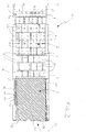
- the rotating chute keeps in a hanging condition by means of the mechanical structure with some inclination within the upper region of the blast furnace; the material is caused to fall close to the impact region 2 where there is the presence of a plurality of box-shaped modules 4 which are positioned adjacent to at least part of this region (and in particular the whole region) in order to retain part of the feed material.
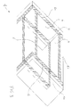
- said modules have a substantially rectangular plan configuration (see Fig. 2) defined by four side walls 4a, 4b transversely emerging from a bottom 7 of the module.
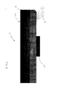
- the box-shaped modules 4 have double side walls 4a and 4b on each side emerging from the bottom (as viewed from Fig. 3) and in particular the innermost wall 6 is generally made of wear-resistant material; obviously, these box-shaped modules can also be made up of a single wall of wear-resistant material for each side.
- At least two of said side walls 4b are inclined to a plane of the impact region 2 and said inclination is directed opposite to a sliding direction 5 of the material being fed to the blast furnace.
- the side walls 4b are inclined by an angle included between 10 and 80 degrees, preferably included between 30 and 60 degrees and of 45° in the embodiment shown.
- box-shaped modules 4 have a bottom 7 generally also made of wear-resistant material and raised with respect to the plane of the impact region 2.
- the above characteristic enables the strength and operating life of the chute to be increased once again.
- the box-shaped modules 4 are separated and independent of each other; in fact each of them has its own side walls independent of those of the adjacent module.
- the modules are disposed in a predetermined number of transverse rows preferably orthogonal to the sliding direction 5 of the feed material and in particular the modules of intermediate rows are disposed laterally offset relative to those of the immediately preceding and immediately following rows.
- box-shaped modules 4 are identical with each other; in addition the same are spaced from the adjacent modules defining collecting/passage routes 8 for the feed material.
- the particular structure and geometry of the box-shaped modules 4 causes the solid space/void space ratio (i.e. the ratio between the regions where the surfaces of the side walls of the box-shaped modules are present - solid spaces - and the "hollow" regions defined between the side walls of the same box-shaped modules - void spaces) to be very balanced and of such a nature that even if the whole impact region 2 and sliding region 3 were defined by the presence of these box-shaped elements it would be possible to obtain a ratio practically identical with that of the chutes in accordance with the known art provided with a pocket impact region and a perfectly smooth sliding region.
- the solid space/void space ratio i.e. the ratio between the regions where the surfaces of the side walls of the box-shaped modules are present - solid spaces - and the "hollow" regions defined between the side walls of the same box-shaped modules - void spaces
- a chute having box-shaped elements 4 over the whole extension thereof would in any case enable the material to reach the necessary and correct speed at the chute exit, with the advantage of greatly increasing the operating life of the sliding region 3 as well.
- the chute can also optionally comprise an upper conveying pipe 30 (Figs. 4 and 5) useful to convey the furnace charge to the furnace centre, when the chute is in the most sloping positions, for example. It aims at preventing the material from jutting out of the chute sides and can possibly be displaced longitudinally on the chute structure depending on the operating requirements.
- a closing structure 10 consisting of at least one first wall 11 transverse to the bottom and the side walls of the chute (in detail orthogonal thereto) which is rigidly fastened to the load bearing structure of the chute at a rearward position relative to the end portion of the load bearing body 12 (as shown in Figs. 1 and 2).
- the fixed wall 11 also has a predetermined number of stiffening ribs disposed on and welded to the outer surface thereof so as to help in stiffening the closing structure 10 itself.
- a second wall 14 is also present, said wall too being transverse to the bottom and generally parallel to the fixed wall 11 although spaced apart therefrom so as to define a gap susceptible of being possibly filled with refractory material.
- This second wall 14 is fastened to the load bearing body 12 as well, but in an at least partly movable manner.
- the wall mobility is in a translation direction substantially parallel to the sliding direction 5 of the feed material.
- a plurality of fastening slots 15 with their bigger diameters disposed horizontally as in the example in Fig. 1 are present and they enable a relative mobility between the load bearing body of the chute and the second wall 14.
- This mobility can for example be utilised to enable better absorption of the impact energy of the charge on the chute itself; in fact, this movable wall can dissipate part of the energy transmitted from the feed material falling down and impacting thereon by friction.
- the second wall 14 is further provided with a predetermined number of beams of substantially T-shaped section 16 emerging from the inner surface of the wall 14 and defining an insulating gap 17 that can possibly be fully or partly filled with further refractory material, such as ceramic fibre or the like (see Fig. 1).
- T-shaped structures are also disposed close to an extension of this second transverse wall 14 thereby emerging both from the side walls and the lower wall of the chute itself.
- the rotating chute being the object of the particular embodiment shown has a cross section of the rear portion of semicircular shape and on the contrary, a cross section of the front portion of rectangular shape, suitable connections obtained by means of straightened out plates being present between the two sections.
- manufacture of a chute of a different shape from the described one can be provided, a fully rectangular or fully semicircular chute or a chute with different combination of sections.
- the structure of the inventive chute appears to be greatly stiffened and improved as compared with chutes manufactured in accordance with the known art.
- an outer load bearing shell 19 made of steel of suitable features with sizes and thickness of about 16 mm.
- a first reinforcing shell 20 having a smaller thickness than the preceding one is disposed internally of said outer monolithic load bearing shell.
- This second shell as well is monolithic.
- the two above mentioned structures are made integral with each other by a plurality of longitudinal and transverse ribs 31 (shown in Fig. 5) interposed therebetween so as to define a sandwich structure that is very rigid also in case of torsional stresses.
- the ribs 31 are mechanically engaged in respective seats present in the outer load bearing shell 19 so as to form a single monolithic rigid cell-like structure with the reinforcing shell 20. Said ribs 31 can be further welded to the structure to give the latter more strength.
- the gap 21 that is defined between the outer load bearing shell 19 and first reinforcing shell 20 can also house suitable insulating and refractory material.
- a second reinforcing shell 22 is also present (made of special steel with a thickness of 8 mm, for example) and it is disposed internally of and secured to the first reinforcing shell 20 (by frontal welding, for example, although any other suitable connecting system can be obviously utilised).
- the second reinforcing shell 22 is monolithic too and extends transversely over the whole sliding region 3 until the impact region 2 so as to give further stiffness and strength to the chute.
- box-shaped modules 4 are secured by welding to said second reinforcing shell 22.
- Three wear-resistant walls are usually engaged internally of said second reinforcing shell 22 (and at the sliding region); said walls are assembled beforehand being secured to each other to form a U-shaped section and then are made integral with the previously described monolithic structure.
- These tree walls appear to be very smooth and made of wear-resistant material to enable sliding of the feed material that in this manner can reach the appropriate speeds and be distributed on the wall in an optimal manner.
- the material-delivering front region 25 is suitably sealed by a closing plug concealing the gaps present between the load bearing shell, first and second reinforcing shells and wear-resistant walls.
- This plug is denoted at 24 in Figs. 1 and 2.
- a protection body 18 disposed at the perimeter of the exit portion, being engaged with and projecting from the closing plug 24.
- This protection body 18 has the function of shielding the chute plates from fire, deviating the flames and increasing the resistance to temperature of said chute. In fact (due to the presence of this element), no flames can enter the gaps between the plates giving rise to deformation and damages.
- the protection body 18 can be internally hollow or filled with refractory material and has the tapering shape shown in the accompanying figures exactly to suitably deviate the flames bursting out of the blast furnace. As can be viewed, said body is disposed at a lower position relative to the plane defined by the sliding region 3 in order to enable the material to be discharged without getting into contact therewith.
- the material moving at high speed jumps over the protection body 18 without causing, by its passage, damages or wear thereto, so that said body can have a longer operating life.
- the invention achieves important advantages.
- the protection body 18 protects the feed-material exit portion which is one of the most delicate regions of the rotating chute.
- the new structure with a rear closure can be more hardly reached by flames and is more resistant to temperatures and mechanical stresses caused by the feed charge, due to the presence of two walls one of which is movable.
- the double bottom wall greatly improves the residual life of the installation as compared with all presently known and marketed types.
- the set of the modifications carried out in the present invention surely enables the mechanical and structural strength of the chute to be increased as well as resistance to temperature and wear.
Landscapes
- Engineering & Computer Science (AREA)
- Mechanical Engineering (AREA)
- General Engineering & Computer Science (AREA)
- Chemical & Material Sciences (AREA)
- Manufacturing & Machinery (AREA)
- Materials Engineering (AREA)
- Metallurgy (AREA)
- Organic Chemistry (AREA)
- Chutes (AREA)
- Blast Furnaces (AREA)
Applications Claiming Priority (1)
| Application Number | Priority Date | Filing Date | Title |
|---|---|---|---|
| ITMI20041799 ITMI20041799A1 (it) | 2004-09-21 | 2004-09-21 | Scivolo di distribuzione particolarmente per altoforni |
Publications (2)
| Publication Number | Publication Date |
|---|---|
| EP1640461A2 true EP1640461A2 (fr) | 2006-03-29 |
| EP1640461A3 EP1640461A3 (fr) | 2007-09-26 |
Family
ID=35677499
Family Applications (1)
| Application Number | Title | Priority Date | Filing Date |
|---|---|---|---|
| EP05108730A Withdrawn EP1640461A3 (fr) | 2004-09-21 | 2005-09-21 | Goulotte de distribution, notamment pour des hauts fourneaux |
Country Status (2)
| Country | Link |
|---|---|
| EP (1) | EP1640461A3 (fr) |
| IT (1) | ITMI20041799A1 (fr) |
Cited By (7)
| Publication number | Priority date | Publication date | Assignee | Title |
|---|---|---|---|---|
| LU91653B1 (en) * | 2010-02-19 | 2011-08-22 | Wurth Paul Sa | Distribution chute for a charging device of a metallurgical reactor |
| EP2537944A2 (fr) | 2011-06-22 | 2012-12-26 | Z & J Technologies GmbH | Dispositif de réception ou de guidage de matériel pour une alimentation d'un haut-fourneau avec de la matière |
| LU92472B1 (en) * | 2014-06-06 | 2015-12-07 | Wurth Paul Sa | Heat protection assembly for a charging installation of a metallurgical reactor |
| CN113355468A (zh) * | 2021-07-14 | 2021-09-07 | 湖南德尚源耐磨工业有限公司 | 一种高炉布料溜槽 |
| WO2023077934A1 (fr) * | 2021-11-08 | 2023-05-11 | 湖南德尚源耐磨工业有限公司 | Grande goulotte de distribution de matériau de haut fourneau présentant une sortie plate |
| CN116479200A (zh) * | 2023-05-06 | 2023-07-25 | 辽宁科技大学 | 一种消除偏载力矩且抗冲击磨损的高炉双布料溜槽 |
| CN119779039A (zh) * | 2025-01-02 | 2025-04-08 | 江苏道金智能制造科技股份有限公司 | 箱式石墨化炉高温粉末烧结输送装置及工作方法 |
Family Cites Families (4)
| Publication number | Priority date | Publication date | Assignee | Title |
|---|---|---|---|---|
| LU73021A1 (fr) * | 1975-07-18 | 1976-03-02 | ||
| GB2047593B (en) * | 1979-03-20 | 1983-06-15 | Sherritt Gordon Mines Ltd | Method of protecting a metallic surface susceptible to abrasion by rock-life material |
| DE3622675A1 (de) * | 1986-07-05 | 1988-01-14 | Joest Gmbh & Co Kg | Schwingfoerderrinne fuer kraetze |
| LU88396A1 (de) * | 1993-08-25 | 1995-03-01 | Wurth Paul Sa | Verteilerschurre fuer Schuettgut |
-
2004
- 2004-09-21 IT ITMI20041799 patent/ITMI20041799A1/it unknown
-
2005
- 2005-09-21 EP EP05108730A patent/EP1640461A3/fr not_active Withdrawn
Cited By (14)
| Publication number | Priority date | Publication date | Assignee | Title |
|---|---|---|---|---|
| LU91653B1 (en) * | 2010-02-19 | 2011-08-22 | Wurth Paul Sa | Distribution chute for a charging device of a metallurgical reactor |
| WO2011101313A1 (fr) * | 2010-02-19 | 2011-08-25 | Paul Wurth S.A. | Goulotte de distribution pour un dispositif de chargement d'un réacteur métallurgique |
| EP2537944A2 (fr) | 2011-06-22 | 2012-12-26 | Z & J Technologies GmbH | Dispositif de réception ou de guidage de matériel pour une alimentation d'un haut-fourneau avec de la matière |
| DE102011051255A1 (de) | 2011-06-22 | 2012-12-27 | Z & J Technologies Gmbh | Materialführungs- oder Aufnahmevorrichtungen für eine Beschickung eines Hochofens mit Material |
| LU92472B1 (en) * | 2014-06-06 | 2015-12-07 | Wurth Paul Sa | Heat protection assembly for a charging installation of a metallurgical reactor |
| WO2015185695A1 (fr) * | 2014-06-06 | 2015-12-10 | Paul Wurth S.A. | Ensemble de protection thermique pour une installation de charge d'un réacteur métallurgique |
| CN106415128A (zh) * | 2014-06-06 | 2017-02-15 | 保尔伍斯股份有限公司 | 用于冶金反应器的装料装置的防热组件 |
| CN106415128B (zh) * | 2014-06-06 | 2019-04-09 | 保尔伍斯股份有限公司 | 冶金反应器的装料装置及用于其的防热组件、防热板 |
| EA033753B1 (ru) * | 2014-06-06 | 2019-11-21 | Wurth Paul Sa | Теплозащитный узел для загрузочной установки металлургического реактора |
| US10648737B2 (en) | 2014-06-06 | 2020-05-12 | Paul Wurth S.A. | Heat protection assembly for a charging installation of a metallurgical reactor |
| CN113355468A (zh) * | 2021-07-14 | 2021-09-07 | 湖南德尚源耐磨工业有限公司 | 一种高炉布料溜槽 |
| WO2023077934A1 (fr) * | 2021-11-08 | 2023-05-11 | 湖南德尚源耐磨工业有限公司 | Grande goulotte de distribution de matériau de haut fourneau présentant une sortie plate |
| CN116479200A (zh) * | 2023-05-06 | 2023-07-25 | 辽宁科技大学 | 一种消除偏载力矩且抗冲击磨损的高炉双布料溜槽 |
| CN119779039A (zh) * | 2025-01-02 | 2025-04-08 | 江苏道金智能制造科技股份有限公司 | 箱式石墨化炉高温粉末烧结输送装置及工作方法 |
Also Published As
| Publication number | Publication date |
|---|---|
| ITMI20041799A1 (it) | 2004-12-21 |
| EP1640461A3 (fr) | 2007-09-26 |
Similar Documents
| Publication | Publication Date | Title |
|---|---|---|
| EP3390945B1 (fr) | Wagon à palettes pour le transport de matériau en vrac pour traitement thermique et son procédé | |
| EP1785684B1 (fr) | Tirant d'extraction pour échangeur de chaleur rotatif, échangeur de chaleur rotatif avec le tirant d'extraction, et procédé de traitement thermique de minerai d'oxyde de nickel | |
| KR100322356B1 (ko) | 장입재료용분배슈트 | |
| JP5659690B2 (ja) | 焼結鉱冷却装置 | |
| JP5410065B2 (ja) | 搬送用構造体 | |
| KR101773454B1 (ko) | 분배 슈트 | |
| CA2320456C (fr) | Dispositif pour prechauffer une charge d'alimentation, comportant des sections de parois de puits remplacables | |
| JP2002180115A (ja) | 耐磨耗性プレート | |
| CN112299041A (zh) | 一种废钢预热加工用竖井料仓 | |
| CN215103015U (zh) | 具有可快速更换的耐磨板的排焦溜槽 | |
| CN113355468B (zh) | 一种高炉布料溜槽 | |
| CN213801997U (zh) | 一种废钢预热加工用竖井料仓 | |
| CN212309757U (zh) | 一种冲击式制砂机的卸料斗及卧轴冲击式制砂机 | |
| CA2420533C (fr) | Procede et dispositif pour repartir un produit en morceaux en vrac | |
| CN201605283U (zh) | 高炉炉顶料罐衬板在线修复结构 | |
| KR20080036753A (ko) | 홈통과 프레임 조립식 구조를 구비한 고로선회슈트 | |
| CN214496367U (zh) | 用于冶金炉的壁板保护系统及冶金炉壁板体 | |
| US4273298A (en) | Apparatus for crushing agglomerated mass | |
| CN216710703U (zh) | 落煤桶组件及输煤系统 | |
| KR200177702Y1 (ko) | 정련로 원료 투입 장치 | |
| CN209623358U (zh) | 烧结机机尾导料槽 | |
| CN210709122U (zh) | 落料点耐冲击格栅衬板 | |
| CN107245541A (zh) | 无料钟高炉称量料罐 | |
| RU20315U1 (ru) | Регенеративный нагревательный колодец | |
| CN202254817U (zh) | 导料槽装置 |
Legal Events
| Date | Code | Title | Description |
|---|---|---|---|
| PUAI | Public reference made under article 153(3) epc to a published international application that has entered the european phase |
Free format text: ORIGINAL CODE: 0009012 |
|
| AK | Designated contracting states |
Kind code of ref document: A2 Designated state(s): AT BE BG CH CY CZ DE DK EE ES FI FR GB GR HU IE IS IT LI LT LU LV MC NL PL PT RO SE SI SK TR |
|
| AX | Request for extension of the european patent |
Extension state: AL BA HR MK YU |
|
| PUAL | Search report despatched |
Free format text: ORIGINAL CODE: 0009013 |
|
| AK | Designated contracting states |
Kind code of ref document: A3 Designated state(s): AT BE BG CH CY CZ DE DK EE ES FI FR GB GR HU IE IS IT LI LT LU LV MC NL PL PT RO SE SI SK TR |
|
| AX | Request for extension of the european patent |
Extension state: AL BA HR MK YU |
|
| AKX | Designation fees paid | ||
| REG | Reference to a national code |
Ref country code: DE Ref legal event code: 8566 |
|
| STAA | Information on the status of an ep patent application or granted ep patent |
Free format text: STATUS: THE APPLICATION IS DEEMED TO BE WITHDRAWN |
|
| 18D | Application deemed to be withdrawn |
Effective date: 20080327 |