EP1640489B1 - Aiguille compound - Google Patents
Aiguille compound Download PDFInfo
- Publication number
- EP1640489B1 EP1640489B1 EP04745753A EP04745753A EP1640489B1 EP 1640489 B1 EP1640489 B1 EP 1640489B1 EP 04745753 A EP04745753 A EP 04745753A EP 04745753 A EP04745753 A EP 04745753A EP 1640489 B1 EP1640489 B1 EP 1640489B1
- Authority
- EP
- European Patent Office
- Prior art keywords
- slider
- fork
- needle member
- needle
- contact surface
- Prior art date
- Legal status (The legal status is an assumption and is not a legal conclusion. Google has not performed a legal analysis and makes no representation as to the accuracy of the status listed.)
- Expired - Lifetime
Links
- 150000001875 compounds Chemical class 0.000 title claims description 25
- 210000002105 tongue Anatomy 0.000 claims abstract description 53
- 239000007787 solid Substances 0.000 claims abstract description 42
- 230000015572 biosynthetic process Effects 0.000 claims description 3
- 238000009940 knitting Methods 0.000 description 10
- 239000002184 metal Substances 0.000 description 4
- 230000000994 depressogenic effect Effects 0.000 description 3
- 239000004744 fabric Substances 0.000 description 2
- 239000000470 constituent Substances 0.000 description 1
- 238000000034 method Methods 0.000 description 1
Images




Classifications
-
- D—TEXTILES; PAPER
- D04—BRAIDING; LACE-MAKING; KNITTING; TRIMMINGS; NON-WOVEN FABRICS
- D04B—KNITTING
- D04B35/00—Details of, or auxiliary devices incorporated in, knitting machines, not otherwise provided for
- D04B35/02—Knitting tools or instruments not provided for in group D04B15/00 or D04B27/00
- D04B35/06—Sliding-tongue needles
Definitions
- the present invention relates to a compound needle used in a knitting machine such as a flat knitting machine.
- the present invention relates to a guide of a slider for a needle member.
- Japanese Laid-Open Patent Publication No. 2002-294541 Japanese Laid-Open Patent Publication No. 2001-032154 , and Japanese Laid-Open Patent Publication No. 62-206069 disclose compound needles.
- a needle member has a fork which is branched from substantially the central position in the longitudinal direction. The fork extends toward a hook side at the front end of the needle member.
- a slider is guided by the lower surface of the fork and the upper surface of the needle member.
- a slider butt is provided in the back portion of the slider, and a pair of support portions are provided at the lower back end of the slider.
- the needle member is sandwiched between the support portions.
- the support portions are considered to be protrusions provided on the slider.
- Japanese Laid-Open Patent Publication No. 2001-032154 discloses a compound needle of a similar type. Instead of providing a fork for the needle member to sandwich the slider, the upper surface of the slider is supported by a metal belt on a needle bed.
- forks are provided for a needle member and a slider, respectively, and the forks engage each other to position the slider.
- An object of the present invention is to prevent upward movement of a butt provided at the back of a slider.
- Another object of the present invention is to increase the strength of a needle member, and simplify processing of the needle member.
- Still another object of the present invention is to provide structure in which the slider can move back and forth easily relative to second and third forks.
- a compound needle comprises a needle member having a hook at its front end, and a slider slidable over the needle member, and having tongues at its front end.
- the needle member and the slider are movable independently for formation and transferring of knit stitches.
- the needle member has a first fork, a second fork, and a third fork.
- the first fork protrudes from a branch portion toward the hook.
- the branch portion is branched upwardly from substantially the central position of a region where the slider slides.
- the front half of the slider is sandwiched between the first fork and the needle member such that the slider is guided by the lower surface of the first fork to limit vertical movement of the front half of the slider.
- the second fork protrudes from the branch portion toward an upper back position of the needle member, and toward a butt of the slider such that the slider is guided by the lower surface of the second fork at a position where the slider has moved forward relative to the needle member.
- the third fork is branched forward from a position of the needle member behind the butt of the slider, and faces the second fork such that the slider is guided by the lower surface of the third fork at a position where the slider has moved back relative to the needle member.
- the second fork and the third fork limit vertical movement of the back half of the slider.
- the butt is provided in the back half of the slider.
- a first fork contact cam surface is provided on the upper surface of the front half of the slider at a position ahead of the through slit, and the first fork contact cam surface is guided by the lower surface of the first fork.
- a second fork contact surface is provided on the upper surface of the back half of the slider at a position ahead of the butt of the slider, and the second fork contact surface is guided by the lower surface of the second fork.
- a third fork contact surface is provided on the upper surface at the back end of the slider behind the butt of the slider, and the third fork contact surface is guided by the lower surface of the third fork.
- the front side and the back side are defined based on the longitudinal direction of the compound needle.
- the hook and the tongues are provided on the front side.
- the slider, the butt, and the third fork are provided on the back side.
- the upper side and the lower side are defined based on the state in which the compound needle is set on a needle bed.
- the slider is positioned above the needle member, and rides (slides) over the needle member.
- the first fork and the second fork are positioned above the slider.
- the slider is sandwiched between the first and second forks and the needle member.
- the left-right direction and the side direction mean the direction perpendicular to both of the longitudinal direction and the vertical direction, and such directions are used, e.g., when referring to thin plates on the left and right sides of the slider of the through slit, or thin plates on the left and right sides of the skirt.
- the back half of the slider is solid, and has substantially the same thickness from the third fork contact surface to the second fork contact surface.
- the slider is separated into two parts on the left side and the right side from a position below the second fork contact surface to the through slit, and the upper surface and the lower surface of the slider are cut at the through slit to form the through slit.
- an oblique tapered portion oriented from the upper back to the lower front is provided at the back end of the second fork;
- the upper surface of the needle member includes an expanded portion expanded upwardly at a position behind the hook of the needle member;
- the bottom of the solid portion around the support portion forms a recess which is curved upwardly, and the recess is provided behind a borderline extending from the upper front to the lower back at the front end on the hook side of the solid portion.
- the height of the slider butt is limited by the second fork, the third fork, and the second fork contact surface and the third fork contact surface. These members can be formed with sufficient strength. Therefore, improvement in the reliability and durability of the needle spring is achieved.
- the back half of the slider is formed to have substantially the same thickness from the third fork contact surface to the second fork contact surface. In the structure, the strength of this portion is increased, and improvement in the durability of the slider is achieved.
- the slider is separated into two parts on the left side and the right side from a position below the second fork contact surface to the through slit, and the upper surface and the lower surface of the slider are cut at the through slit. In this manner, the slider can be fabricated easily by cutting. Further, by separating the slider at a position below the second fork contact surface into the two left and right parts, the border between the solid portion near the slider butt and the portion having the two left and right parts near the through slit becomes long. Therefore, damage due to the stress concentration to the border can be prevented.
- the tapered portions oriented obliquely from the upper back to the lower front are provided at the back end of the second fork and at the front end of the second fork contact surface. In the structure, it is possible to smoothly guide the second fork contact surface under the second fork.
- the tapered portions oriented obliquely from the front to the lower back are provided at the front end of the third fork and the back end of the third fork contact surface. In the structure, it is possible to smoothly guide the third fork contact surface by the lower surface of the third fork.
- the bottom of the solid portion above the skirt is supported by the upper surface of the needle member.
- the support portion Since the distance between the tongues and the support portion is small, it is possible to improve the rigidity of the tongues, and prevent flexure deformation or the like of the tongues. Thus, at the time of knitting using a hard knitting yarn or knitting a yarn in dense stitches, knitting operation can be performed easily.
- the borderline of the solid portion of the front half of the slider, on the hook side, extending from the upper front to the lower back will be considered.
- the borderline is a borderline between the tongues and the skirt separated into two parts, and the solid portion.
- FIGS. 1 and 2 show a needle member according to a first embodiment.
- the needle member 2 includes a main body 4 and an extension 6.
- a hook 8 is provided at the front end of the needle member 2.
- a branch portion 10 is provided near the center of the main body 4.
- the branch portion 10 is branched into a first fork 12 on the front side, and a second fork 14 on the back side.
- the lower surface of the first fork 12 on the front side of the branch portion 10 forms a guide 13 for guiding the upper surface of a slider.
- the lower surface of the second fork 14 on the back side of the branch portion 10 forms a guide surface 15.
- the needle member 2 is curved upwardly from a position near the back end of the main body 4.
- a third fork 16 protrudes forward from a position obliquely behind, and above the back end of the main body 4.
- the lower surface of the third fork 16 forms a guide surface 17.
- a tapered portion 18 is provided at the back end of the second fork 14.
- the tapered portion 18 is tapered obliquely from the upper back to the lower front.
- a tapered portion 19 is provided at the front end of the third fork 16.
- the tapered portion 19 is tapered obliquely from the upper front to the lower back.
- the front side and the back side are defined based on the longitudinal direction of the needle member 2 or the slider 30.
- the hook 8 is provided on the front side, and the third fork 16 or the like are provided on the back side.
- the needle member 2 is accommodated in a needle bed (not shown), and slides back and forth along the needle bed.
- the lower side and the upper side are defined by the lower sides and upper sides in FIGS. 1 , 3 , and 5 .
- Side surfaces of the needle member 2 mean two side surfaces along the longitudinal direction in FIG. 2 . It should be noted that two side surfaces shown on the upper and lower sides in FIG. 4 are left and right side surfaces of the slider 30.
- a cheek 20 is provided at a position slightly backward from the hook 8 where the height is increased upwardly.
- the cheek 20 includes a dimple portion 21.
- Upper part of the dimple portion 21 (upper surface of the needle member) is swelled upwardly to form an upwardly expanded surface 22.
- the dimple portion 21 is provided by dimple formation process of the needle member 2 at the portion of the cheek 20.
- the dimple portion 21 has a rectangular shape, and is oriented obliquely from the lower back to the upper front.
- the front side of the dimple portion 21 is on the side of the hook 8.
- the hook 8 When the hook 8 is fully opened ( FIG. 8 ), the tongues 32, 32 are depressed into the left and right dimple portions 21, 21 such that the tongues 32, 32 do not protrude from the side surfaces of the needle member 2.
- a reference numeral 23 schematically denotes a needle butt for moving the needle member 2 back and forth.
- a needle member 3 shown in FIG. 3 includes a main body 5 and a needle jack 7 separately.
- a fitting recess 24 is provided in the main body 5, and a fitting protrusion 25 is provided in the needle jack 7.
- the fitting recess 24 and the fitting protrusion 25 are fitted to each other to combine the main body 5 and the needle jack 7 together.
- the fitting protrusion may be provided on the side of the needle body 5, and the fitting recess may be provided on the side of the needle jack 7.
- the needle member 3 in FIG. 3 since the third fork 16 is provided on the side of the needle jack 7, attachment/detachment of the slider 30 is easy, and it is possible to produce the slider 30 easily.
- the difference between the needle member 2 and the needle member 3 is whether the main body and the needle jack are separated into two components or formed integrally into one piece.
- the needle member 2 and the needle member 3 are the same in other respects. Description about the needle member 2 is applicable to the needle member 3, and description about the needle member 3 is applicable to the needle member 2. In the embodiments, the same constituent elements are labeled with the same reference numeral.
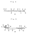
- FIGS. 4 and 5 show the slider 30.
- a pair of left and right tongues 32, 32 are present.
- a slit 33 is formed between the tongues 32, 32.
- the tongues 32, 32 are spaced away from each other toward the left side and the right side from the slit 33 at the central position.
- the tongues 32, 32 are bent such that the front ends of the tongues 32, 32 contact each other. Tongues or a hook of another slider can be inserted into the slit 33.
- a nose 34 is present at a position slightly backward from the tongues 32.
- the nose 34 is expanded upwardly for preventing backward movement of the stitch loop held by the tongues 32, beyond the nose 34.
- a through slit portion 36 is provided at the center of the slider 30, a through slit portion 36 is provided.
- the slider 30 is separated into the left part and the right part.
- a through slit 37 is formed between the left part of and the right part of the through slit portion 36.
- the through slit portion 36 is swelled to the left and right for generating friction with, e.g., the wall surface of the needle groove of the needle bed to prevent unwanted movement of the slider 30.
- a front solid portion 38 is provided on the front side of the through slit portion 36, and a back solid portion 40 is provided on the back side of the through slit portion 36.
- the slider 30 is solid in these solid portions 38, 40.
- the thickness is constant in the solid portion 38, and the thickness is constant in the solid portion 40.
- a first fork contact cam surface 39 is formed on the upper surface of the solid portion 38.
- the first fork contact cam surface 39 contacts the guide 13 on the lower surface of the first fork 12 for limiting vertical movement of the solid portion 38.
- the slider 30 is separated into the left part and the right part to form the tongues 32, the nose 32, and a skirt 41.
- the skirt 41 slides on the main body 4 or 5 from a portion facing the lower side of the first fork 12 to the portion of the cheek 20.
- the expanded surface 22 supports the bottom surface of the solid portion 38 to prevent the front half of the slider from being depressed.
- a slider butt 42 protrudes upwardly.
- a second fork contact surface 44 is present on the front side of the slider butt 42.
- a tapered potion 45 is formed at the front end of the second fork contact surface 44. The tapered portion 45 is oriented from the upper back to the lower front.
- a third fork contact surface 46 is present on the back side of the slider butt 42.
- a tapered portion 47 is formed at the back end of the third fork contact surface 46. The tapered portion 47 is oriented from the upper front to the lower back.
- a borderline 48 between the solid portion 40 and the through slit portion 36 is in parallel with the second fork contact surface 44. Since the length of the borderline 48 is large, the stress applied to the borderline 48 can be distributed broadly.
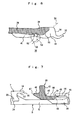
- FIG. 6 is an enlarged view showing an area around the solid portion 38 in the front half of the slider 30.
- the borderline 50 is an oblique borderline on the front side of the solid portion 38.
- the tongues 32 and the nose 34 are provided on the front side of the solid portion 38.
- An upwardly curved recess 52 is formed on the back side of the borderline 50.
- the front half of the recess 52 forms a support portion 53.
- the support portion 53 contacts the expanded surface 22 to prevent flexure deformation of the tongues 32.
- the expanded surface 22 is positioned on the upper front half of the dimple portion 21. Since the distance between the support portion 53 and the tongues 32 is small, it is possible to improve the rigidity of the tongues 32.
- FIG. 7 shows the relationship between the second fork 14 and the second fork contact surface 44, and the relationship between the third fork 16 and the third fork contact surface 46.
- the second fork contact surface 44 is supported by the second fork 14.
- the third fork contact surface 46 is supported by the third fork 16.
- the solid portion 40 is guided by the tapered portions 18, 45 or the tapered portions 19, 47.
- the solid portion 40 is solid having the constant thickness in the wide range extending from the third fork contact surface 46 to the second fork contact surface 44. Therefore, the strength of the solid portion 40 is high. Further, the stress applied to the border between the solid portion 40 and the through slit portion 36 is distributed by making the borderline 48 longer.
- FIGS. 8 to 10 show three states of the compound needle.
- a reference numeral 60 denotes a metal band on the needle bed side.
- the metal band 60 contacts the upper surface of the first fork 12 or the upper surface of the second fork 14 to prevent the compound needle from floating above the needle groove of the needle bed.
- FIG. 8 shows a state in which the hook 8 has moved forward to the front end position, and the slider 30 has moved back to the back end position with respect to the needle member.
- the guide 13 at the lower surface of the first fork 12 applies a force to push the first fork contact cam surface 39 downwardly, and the force is operated to move the slider butt 42 upwardly.
- the third fork contact surface 46 contacts the third fork 16 to prevent the slider butt 42 from moving upwardly.
- the tongues 32 are depressed into the left and right dimple portions 21 of the needle main body 2, and do not protrude to the sides of the needle main body 2. Therefore, the stitch on the hook 8 can be transferred to the tongues 32 easily.
- FIG. 9 shows a state in which the tongues 32 close the hook 8, by the force from a stitch loop held by the tongues 32 or the like, a force which bounces the slider butt 42 upwardly is generated. This force is supported by the second fork contact surface 44 and the second fork 14 to prevent the unwanted upward movement of the slider butt 42.
- This mechanism is also applicable to a case of FIG. 10 in which the tongues 32 have moved further forward.
- FIG. 10 shows a state in which the slider 30 has moved forward to the front end position with respect to the needle member 3.
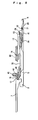
- FIG. 11 is an enlarged view showing the state of FIG. 9 .
- a stitch loop 62 is held by the tongues 32. Since tension is applied to the knitted fabric, e.g., by racking operation of the needle bed or drawing the knitted fabric downwardly, a force in the left-right direction is applied to the tongues 32. Further, a force is applied from the stitch loop 62 to the tongues 32 downwardly.
- the slider 30 is separated into the left part and the right part. Therefore, the rigidity of the tongues 32 is low. For example, this is required for moving the stitch loop by inserting tongues or a hook of another compound needle into the gap between the tongues 32, 32.
- the support portion 53 is positioned slightly backward from the oblique borderline 50 at the front of the solid portion 38.
- the support portion 53 contacts the expanded surface 22 on the side of the needle member 3.
- the bottom surface of the solid portion 38 is supported. In this manner, the distance between the support portion 53 and the tongues 32 is reduced, and flexure deformation of the tongues 32 is prevented.
Landscapes
- Engineering & Computer Science (AREA)
- Textile Engineering (AREA)
- Knitting Machines (AREA)
- Infusion, Injection, And Reservoir Apparatuses (AREA)
- Air-Conditioning For Vehicles (AREA)
Claims (6)
- Aiguille composite comprenant un élément d'aiguille (2) comportant un crochet (8) à une extrémité avant de l'élément d'aiguille (2) et un élément coulissant (30) pouvant coulisser sur l'élément d'aiguille (2) et comportant des langues (32) à une extrémité de l'élément coulissant (30), l'élément d'aiguille (2) et l'élément coulissant (30) étant mobiles indépendamment pour la formation et le transfert de mailles, caractérisée en ce que :l'élément d'aiguille (2) comprend une première fourche (12), une deuxième fourche (14) et une troisième fourche (16) ;la première fourche (12) fait saillie à partir d'une partie de branche (10) vers le crochet (8), la partie de branche (10) est divisée vers le haut à partir d'une position sensiblement centrale d'une région de l'élément d'aiguille (2) dans laquelle l'élément coulissant (30) glisse, une moitié avant de l'élément coulissant (30) est prise en sandwich entre la première fourche (12) et l'élément d'aiguille (2) de sorte que l'élément coulissant (30) est guidé par la surface inférieure de la première fourche (12) pour limiter le déplacement vertical de la moitié avant de l'élément coulissant (30) ;la deuxième fourche (14) fait saillie à partir de la partie de branchement (10) vers une position arrière supérieure de l'élément d'aiguille (2) et vers une butée (42) de l'élément coulissant (30) de sorte que l'élément coulissant (30) est guidé par la surface inférieure de la deuxième fourche (14) à une position où l'élément coulissant (30) s'est déplacé vers l'avant par rapport à l'élément d'aiguille (2) ;la troisième fourche (16) est divisée vers l'avant à partir d'une position en arrière de la butée (42) de l'élément coulissant (30) de l'élément d'aiguille (2) et fait face à la deuxième fourche (14) de sorte que l'élément coulissant (30) est guidé par la surface inférieure de la troisième fourche (16) à une position où l'élément coulissant (30) s'est déplacé vers l'arrière par rapport à l'élément d'aiguille (2) ; etla deuxième fourche (14) et la troisième fourche (16) limitent le déplacement vertical de la moitié arrière de l'élément coulissant (30) ;et en ce que :l'élément coulissant (30) comprend la butée (42), une fente (33), une surface de came de contact de première fourche (39), une surface de contact de deuxième fourche (44) et une surface de contact de troisième fourche (46) ;la butée (42) est prévue dans la moitié arrière de l'élément coulissant (30) ;la fente (33) passe verticalement à travers l'élément coulissant (30) à une position en avant de la butée (42) et la partie de branchement (10) de l'élément d'aiguille (2) passe par la fente (33) ;la surface de came de contact de première fourche (39) est formée sur la surface supérieure de la moitié avant de l'élément coulissant (30) à une position en avant de la fente (33) à guider par la surface inférieure de la première fourche (12) ;la surface de contact de deuxième fourche (44) est prévue sur la surface supérieure de la moitié arrière de l'élément coulissant (30) à une position en avant de la butée (42) de l'élément coulissant (30) à guider par la surface inférieure de la deuxième fourche (14) ; etla surface de contact de troisième fourche (46) est prévue sur la surface supérieure de l'extrémité arrière de l'élément coulissant (30) derrière la butée (42) de l'élément coulissant (30) à guider par la surface inférieure de la troisième fourche (16).
- Aiguille composite selon la revendication 1, caractérisée en ce que la moitié arrière de l'élément coulissant (30) est pleine et a sensiblement la même épaisseur à partir de la surface de contact de la troisième fourche (46) jusqu'à la surface de contact de la deuxième fourche (44).
- Aiguille composite selon la revendication 1, caractérisée en ce que l'élément coulissant (30) est séparé en deux parties du côté gauche et du côté droit à partir d'une position située en-dessous de la surface de contact (44) de deuxième fourche vers la fente (33), et la surface supérieure et la surface inférieure de l'élément coulissant (30) sont coupées au niveau de la fente (33) pour former la fente (33).
- Aiguille composite selon la revendication 1, caractérisée en ce que :une partie conique oblique (18) orientée de la partie arrière haute vers la partie avant basse est prévue à une extrémité arrière de la deuxième fourche (14) ;une partie conique oblique (19) orientée de la partie avant haute vers la partie arrière basse est prévue au niveau d'une extrémité avant de la troisième fourche (14) ;une partie conique oblique orientée de la partie arrière haute vers la partie avant basse est prévue au niveau d'une extrémité avant de la surface de contact (44) de deuxième fourche ; etune partie conique oblique (47) orientée de la partie avant haute vers la partie arrière basse est prévue au niveau d'une extrémité arrière de la surface de contact de troisième fourche (46).
- Aiguille composite selon la revendication 1, caractérisée en ce que la surface supérieure de l'élément d'aiguille (2) inclut une partie en extension (22), en extension vers le haut à une position à l'arrière du crochet de l'élément d'aiguille (2) ;une partie supérieure de la moitié avant de l'élément coulissant (30) forme une partie pleine (38) et une partie inférieure de la moitié avant de l'élément coulissant (30) forme une jupe (41) séparée en deux parties ; etquand les langues (32) ferment le crochet (8), une partie support (53) prévue en bas de la partie pleine au-dessus de la jupe (41) est portée par une position de côté du crochet de la partie en extension (22).
- Aiguille composite selon la revendication 5, caractérisée en ce que, dans la moitié avant de l'élément coulissant (30), le bas de la partie pleine (38) autour de la partie de support (53) forme un creux (52) qui est courbé vers le haut et le creux (52) est prévu entre une limite (50) s'étendant à partir de la partie avant haute vers la partie arrière basse à l'extrémité avant du côté du crochet de la partie pleine (38).
Applications Claiming Priority (2)
| Application Number | Priority Date | Filing Date | Title |
|---|---|---|---|
| JP2003180861A JP3983720B2 (ja) | 2003-06-25 | 2003-06-25 | 複合針 |
| PCT/JP2004/008123 WO2005001186A1 (fr) | 2003-06-25 | 2004-06-10 | Aiguille « compound » |
Publications (3)
| Publication Number | Publication Date |
|---|---|
| EP1640489A1 EP1640489A1 (fr) | 2006-03-29 |
| EP1640489A4 EP1640489A4 (fr) | 2006-07-19 |
| EP1640489B1 true EP1640489B1 (fr) | 2008-10-01 |
Family
ID=33549512
Family Applications (1)
| Application Number | Title | Priority Date | Filing Date |
|---|---|---|---|
| EP04745753A Expired - Lifetime EP1640489B1 (fr) | 2003-06-25 | 2004-06-10 | Aiguille compound |
Country Status (5)
| Country | Link |
|---|---|
| EP (1) | EP1640489B1 (fr) |
| JP (1) | JP3983720B2 (fr) |
| AT (1) | ATE409770T1 (fr) |
| DE (1) | DE602004016849D1 (fr) |
| WO (1) | WO2005001186A1 (fr) |
Cited By (2)
| Publication number | Priority date | Publication date | Assignee | Title |
|---|---|---|---|---|
| DE102007039973C5 (de) * | 2007-08-23 | 2017-11-02 | Hugo Kern Und Liebers Gmbh & Co. Kg Platinen- Und Federnfabrik | Strick- oder Kettenwirkmaschine zur Maschenstoffherstellung mit zugehörigen Schwinggliednadeln |
| KR20220130238A (ko) * | 2020-04-29 | 2022-09-26 | 그로츠-베케르트 카게 | 편직기를 위한 복합 바늘 |
Families Citing this family (5)
| Publication number | Priority date | Publication date | Assignee | Title |
|---|---|---|---|---|
| JP5719544B2 (ja) * | 2010-08-06 | 2015-05-20 | 株式会社島精機製作所 | 横編機の複合針 |
| JP5618778B2 (ja) * | 2010-11-22 | 2014-11-05 | 株式会社島精機製作所 | 横編機の複合針 |
| DE102013105239A1 (de) * | 2013-05-22 | 2014-11-27 | Groz-Beckert Kg | Schiebernadel |
| JP6980253B2 (ja) * | 2017-06-19 | 2021-12-15 | オルガン針株式会社 | メリヤス針 |
| CN110438655B (zh) * | 2019-08-13 | 2024-04-02 | 宁波慈星股份有限公司 | 一种横机的复合针 |
Family Cites Families (4)
| Publication number | Priority date | Publication date | Assignee | Title |
|---|---|---|---|---|
| JPS62206069A (ja) * | 1986-02-28 | 1987-09-10 | シバタ製針株式会社 | 編機用の複合針 |
| JP2001032154A (ja) * | 1999-07-15 | 2001-02-06 | Shima Seiki Mfg Ltd | 編機用複合針 |
| TW477845B (en) * | 1999-10-27 | 2002-03-01 | Shima Seiki Mfg | Guide mechanism of knitting member and compound needle assembling the guide mechanism therein |
| FR2821093B1 (fr) * | 2001-02-20 | 2003-05-09 | Steiger S A C Atel Const | Aiguille a coulisse pour machine a tricoter |
-
2003
- 2003-06-25 JP JP2003180861A patent/JP3983720B2/ja not_active Expired - Fee Related
-
2004
- 2004-06-10 DE DE602004016849T patent/DE602004016849D1/de not_active Expired - Lifetime
- 2004-06-10 AT AT04745753T patent/ATE409770T1/de not_active IP Right Cessation
- 2004-06-10 WO PCT/JP2004/008123 patent/WO2005001186A1/fr not_active Ceased
- 2004-06-10 EP EP04745753A patent/EP1640489B1/fr not_active Expired - Lifetime
Cited By (2)
| Publication number | Priority date | Publication date | Assignee | Title |
|---|---|---|---|---|
| DE102007039973C5 (de) * | 2007-08-23 | 2017-11-02 | Hugo Kern Und Liebers Gmbh & Co. Kg Platinen- Und Federnfabrik | Strick- oder Kettenwirkmaschine zur Maschenstoffherstellung mit zugehörigen Schwinggliednadeln |
| KR20220130238A (ko) * | 2020-04-29 | 2022-09-26 | 그로츠-베케르트 카게 | 편직기를 위한 복합 바늘 |
Also Published As
| Publication number | Publication date |
|---|---|
| JP2005015945A (ja) | 2005-01-20 |
| EP1640489A1 (fr) | 2006-03-29 |
| EP1640489A4 (fr) | 2006-07-19 |
| ATE409770T1 (de) | 2008-10-15 |
| DE602004016849D1 (de) | 2008-11-13 |
| JP3983720B2 (ja) | 2007-09-26 |
| WO2005001186A1 (fr) | 2005-01-06 |
Similar Documents
| Publication | Publication Date | Title |
|---|---|---|
| EP1640489B1 (fr) | Aiguille compound | |
| JP5844586B2 (ja) | 横編機の選針システム、セレクタ、および横編機 | |
| EP2423363B1 (fr) | Metier a mailles cueillies equipe d'une platine mobile | |
| EP2397589B1 (fr) | Aiguille de type compound pour les machines à tricoter rectiligne | |
| EP2474654B1 (fr) | Dispositif de sélection d'aiguille dans une machine à tricoter rectiligne et sélecteur | |
| EP1178141A1 (fr) | Aiguille composite de machine a tricoter | |
| EP2305866A1 (fr) | Métier à mailles cueillies équipé d'une platine mobile | |
| US20040093911A1 (en) | Yarn carrier of weft knitting device | |
| EP1655398B1 (fr) | Metier a mailles cueillies a platine d'abattage mobile | |
| US20230013090A1 (en) | Element member and slide fastener-attached product | |
| US7380419B2 (en) | Movable sinker apparatus and sinker of weft knitting machine | |
| KR100384734B1 (ko) | 편직기용슬라이더타입편침(編針) | |
| EP2415917B1 (fr) | Aiguille de type compound pour machine à tricoter rectiligne | |
| EP2599906B1 (fr) | Aiguille de type compound pour machine à tricoter rectiligne | |
| CN115348827B (zh) | 拉头结构体及拉头罩 | |
| KR20050083829A (ko) | 복합바늘 | |
| US20040093909A1 (en) | Composite needle | |
| KR101356443B1 (ko) | 트랜스퍼 리시빙 니들용 캠 장치 | |
| CN100494536C (zh) | 具有可动沉降片的横机 | |
| JP2024134918A (ja) | ミシンフット、及びそれを備えたミシン | |
| JP6234244B2 (ja) | 可動シンカーを備える横編機 | |
| JP4175978B2 (ja) | 可動シンカーを備える横編機 | |
| KR101844264B1 (ko) | 고정싱커를 구비하는 횡편기 | |
| CN101809215B (zh) | 横机的选针机构、横机的选针机构用选针片及横机的选针机构用隔距片 | |
| CN218969508U (zh) | 电磁吸附型选择部件 |
Legal Events
| Date | Code | Title | Description |
|---|---|---|---|
| PUAI | Public reference made under article 153(3) epc to a published international application that has entered the european phase |
Free format text: ORIGINAL CODE: 0009012 |
|
| 17P | Request for examination filed |
Effective date: 20051217 |
|
| AK | Designated contracting states |
Kind code of ref document: A1 Designated state(s): AT BE BG CH CY CZ DE DK EE ES FI FR GB GR HU IE IT LI LU MC NL PL PT RO SE SI SK TR |
|
| A4 | Supplementary search report drawn up and despatched |
Effective date: 20060619 |
|
| DAX | Request for extension of the european patent (deleted) | ||
| 17Q | First examination report despatched |
Effective date: 20061208 |
|
| GRAP | Despatch of communication of intention to grant a patent |
Free format text: ORIGINAL CODE: EPIDOSNIGR1 |
|
| GRAS | Grant fee paid |
Free format text: ORIGINAL CODE: EPIDOSNIGR3 |
|
| GRAA | (expected) grant |
Free format text: ORIGINAL CODE: 0009210 |
|
| AK | Designated contracting states |
Kind code of ref document: B1 Designated state(s): AT BE BG CH CY CZ DE DK EE ES FI FR GB GR HU IE IT LI LU MC NL PL PT RO SE SI SK TR |
|
| REG | Reference to a national code |
Ref country code: GB Ref legal event code: FG4D |
|
| REG | Reference to a national code |
Ref country code: CH Ref legal event code: EP |
|
| REG | Reference to a national code |
Ref country code: IE Ref legal event code: FG4D |
|
| REF | Corresponds to: |
Ref document number: 602004016849 Country of ref document: DE Date of ref document: 20081113 Kind code of ref document: P |
|
| PG25 | Lapsed in a contracting state [announced via postgrant information from national office to epo] |
Ref country code: SI Free format text: LAPSE BECAUSE OF FAILURE TO SUBMIT A TRANSLATION OF THE DESCRIPTION OR TO PAY THE FEE WITHIN THE PRESCRIBED TIME-LIMIT Effective date: 20081001 |
|
| NLV1 | Nl: lapsed or annulled due to failure to fulfill the requirements of art. 29p and 29m of the patents act | ||
| PG25 | Lapsed in a contracting state [announced via postgrant information from national office to epo] |
Ref country code: BG Free format text: LAPSE BECAUSE OF FAILURE TO SUBMIT A TRANSLATION OF THE DESCRIPTION OR TO PAY THE FEE WITHIN THE PRESCRIBED TIME-LIMIT Effective date: 20090101 Ref country code: ES Free format text: LAPSE BECAUSE OF FAILURE TO SUBMIT A TRANSLATION OF THE DESCRIPTION OR TO PAY THE FEE WITHIN THE PRESCRIBED TIME-LIMIT Effective date: 20090112 Ref country code: AT Free format text: LAPSE BECAUSE OF FAILURE TO SUBMIT A TRANSLATION OF THE DESCRIPTION OR TO PAY THE FEE WITHIN THE PRESCRIBED TIME-LIMIT Effective date: 20081001 |
|
| PG25 | Lapsed in a contracting state [announced via postgrant information from national office to epo] |
Ref country code: PT Free format text: LAPSE BECAUSE OF FAILURE TO SUBMIT A TRANSLATION OF THE DESCRIPTION OR TO PAY THE FEE WITHIN THE PRESCRIBED TIME-LIMIT Effective date: 20090302 Ref country code: PL Free format text: LAPSE BECAUSE OF FAILURE TO SUBMIT A TRANSLATION OF THE DESCRIPTION OR TO PAY THE FEE WITHIN THE PRESCRIBED TIME-LIMIT Effective date: 20081001 Ref country code: NL Free format text: LAPSE BECAUSE OF FAILURE TO SUBMIT A TRANSLATION OF THE DESCRIPTION OR TO PAY THE FEE WITHIN THE PRESCRIBED TIME-LIMIT Effective date: 20081001 Ref country code: FI Free format text: LAPSE BECAUSE OF FAILURE TO SUBMIT A TRANSLATION OF THE DESCRIPTION OR TO PAY THE FEE WITHIN THE PRESCRIBED TIME-LIMIT Effective date: 20081001 |
|
| PG25 | Lapsed in a contracting state [announced via postgrant information from national office to epo] |
Ref country code: EE Free format text: LAPSE BECAUSE OF FAILURE TO SUBMIT A TRANSLATION OF THE DESCRIPTION OR TO PAY THE FEE WITHIN THE PRESCRIBED TIME-LIMIT Effective date: 20081001 Ref country code: RO Free format text: LAPSE BECAUSE OF FAILURE TO SUBMIT A TRANSLATION OF THE DESCRIPTION OR TO PAY THE FEE WITHIN THE PRESCRIBED TIME-LIMIT Effective date: 20081001 Ref country code: DK Free format text: LAPSE BECAUSE OF FAILURE TO SUBMIT A TRANSLATION OF THE DESCRIPTION OR TO PAY THE FEE WITHIN THE PRESCRIBED TIME-LIMIT Effective date: 20081001 Ref country code: BE Free format text: LAPSE BECAUSE OF FAILURE TO SUBMIT A TRANSLATION OF THE DESCRIPTION OR TO PAY THE FEE WITHIN THE PRESCRIBED TIME-LIMIT Effective date: 20081001 |
|
| PLBE | No opposition filed within time limit |
Free format text: ORIGINAL CODE: 0009261 |
|
| STAA | Information on the status of an ep patent application or granted ep patent |
Free format text: STATUS: NO OPPOSITION FILED WITHIN TIME LIMIT |
|
| PG25 | Lapsed in a contracting state [announced via postgrant information from national office to epo] |
Ref country code: SE Free format text: LAPSE BECAUSE OF FAILURE TO SUBMIT A TRANSLATION OF THE DESCRIPTION OR TO PAY THE FEE WITHIN THE PRESCRIBED TIME-LIMIT Effective date: 20090101 Ref country code: CZ Free format text: LAPSE BECAUSE OF FAILURE TO SUBMIT A TRANSLATION OF THE DESCRIPTION OR TO PAY THE FEE WITHIN THE PRESCRIBED TIME-LIMIT Effective date: 20081001 |
|
| 26N | No opposition filed |
Effective date: 20090702 |
|
| PG25 | Lapsed in a contracting state [announced via postgrant information from national office to epo] |
Ref country code: SK Free format text: LAPSE BECAUSE OF FAILURE TO SUBMIT A TRANSLATION OF THE DESCRIPTION OR TO PAY THE FEE WITHIN THE PRESCRIBED TIME-LIMIT Effective date: 20081001 |
|
| PG25 | Lapsed in a contracting state [announced via postgrant information from national office to epo] |
Ref country code: MC Free format text: LAPSE BECAUSE OF NON-PAYMENT OF DUE FEES Effective date: 20090630 |
|
| REG | Reference to a national code |
Ref country code: CH Ref legal event code: PL |
|
| GBPC | Gb: european patent ceased through non-payment of renewal fee |
Effective date: 20090610 |
|
| REG | Reference to a national code |
Ref country code: FR Ref legal event code: ST Effective date: 20100226 |
|
| REG | Reference to a national code |
Ref country code: IE Ref legal event code: MM4A |
|
| PG25 | Lapsed in a contracting state [announced via postgrant information from national office to epo] |
Ref country code: LI Free format text: LAPSE BECAUSE OF NON-PAYMENT OF DUE FEES Effective date: 20090630 Ref country code: FR Free format text: LAPSE BECAUSE OF NON-PAYMENT OF DUE FEES Effective date: 20090630 Ref country code: CH Free format text: LAPSE BECAUSE OF NON-PAYMENT OF DUE FEES Effective date: 20090630 Ref country code: IE Free format text: LAPSE BECAUSE OF NON-PAYMENT OF DUE FEES Effective date: 20090610 |
|
| PG25 | Lapsed in a contracting state [announced via postgrant information from national office to epo] |
Ref country code: GB Free format text: LAPSE BECAUSE OF NON-PAYMENT OF DUE FEES Effective date: 20090610 |
|
| PG25 | Lapsed in a contracting state [announced via postgrant information from national office to epo] |
Ref country code: GR Free format text: LAPSE BECAUSE OF FAILURE TO SUBMIT A TRANSLATION OF THE DESCRIPTION OR TO PAY THE FEE WITHIN THE PRESCRIBED TIME-LIMIT Effective date: 20090102 |
|
| PG25 | Lapsed in a contracting state [announced via postgrant information from national office to epo] |
Ref country code: LU Free format text: LAPSE BECAUSE OF NON-PAYMENT OF DUE FEES Effective date: 20090610 |
|
| PG25 | Lapsed in a contracting state [announced via postgrant information from national office to epo] |
Ref country code: HU Free format text: LAPSE BECAUSE OF FAILURE TO SUBMIT A TRANSLATION OF THE DESCRIPTION OR TO PAY THE FEE WITHIN THE PRESCRIBED TIME-LIMIT Effective date: 20090402 |
|
| PG25 | Lapsed in a contracting state [announced via postgrant information from national office to epo] |
Ref country code: TR Free format text: LAPSE BECAUSE OF FAILURE TO SUBMIT A TRANSLATION OF THE DESCRIPTION OR TO PAY THE FEE WITHIN THE PRESCRIBED TIME-LIMIT Effective date: 20081001 |
|
| PG25 | Lapsed in a contracting state [announced via postgrant information from national office to epo] |
Ref country code: CY Free format text: LAPSE BECAUSE OF FAILURE TO SUBMIT A TRANSLATION OF THE DESCRIPTION OR TO PAY THE FEE WITHIN THE PRESCRIBED TIME-LIMIT Effective date: 20081001 |
|
| PGFP | Annual fee paid to national office [announced via postgrant information from national office to epo] |
Ref country code: DE Payment date: 20160607 Year of fee payment: 13 |
|
| PGFP | Annual fee paid to national office [announced via postgrant information from national office to epo] |
Ref country code: IT Payment date: 20160621 Year of fee payment: 13 |
|
| REG | Reference to a national code |
Ref country code: DE Ref legal event code: R119 Ref document number: 602004016849 Country of ref document: DE |
|
| PG25 | Lapsed in a contracting state [announced via postgrant information from national office to epo] |
Ref country code: DE Free format text: LAPSE BECAUSE OF NON-PAYMENT OF DUE FEES Effective date: 20180103 |
|
| PG25 | Lapsed in a contracting state [announced via postgrant information from national office to epo] |
Ref country code: IT Free format text: LAPSE BECAUSE OF NON-PAYMENT OF DUE FEES Effective date: 20170610 |