EP1640595A1 - Moteur à combustion interne à suralimentation et procédé pour faire fonctionner un tel moteur à combustion interne - Google Patents
Moteur à combustion interne à suralimentation et procédé pour faire fonctionner un tel moteur à combustion interne Download PDFInfo
- Publication number
- EP1640595A1 EP1640595A1 EP04104583A EP04104583A EP1640595A1 EP 1640595 A1 EP1640595 A1 EP 1640595A1 EP 04104583 A EP04104583 A EP 04104583A EP 04104583 A EP04104583 A EP 04104583A EP 1640595 A1 EP1640595 A1 EP 1640595A1
- Authority
- EP
- European Patent Office
- Prior art keywords
- turbine
- exhaust gas
- internal combustion
- combustion engine
- compressor
- Prior art date
- Legal status (The legal status is an assumption and is not a legal conclusion. Google has not performed a legal analysis and makes no representation as to the accuracy of the status listed.)
- Withdrawn
Links
Images


Classifications
-
- F—MECHANICAL ENGINEERING; LIGHTING; HEATING; WEAPONS; BLASTING
- F02—COMBUSTION ENGINES; HOT-GAS OR COMBUSTION-PRODUCT ENGINE PLANTS
- F02D—CONTROLLING COMBUSTION ENGINES
- F02D9/00—Controlling engines by throttling air or fuel-and-air induction conduits or exhaust conduits
- F02D9/04—Controlling engines by throttling air or fuel-and-air induction conduits or exhaust conduits concerning exhaust conduits
-
- F—MECHANICAL ENGINEERING; LIGHTING; HEATING; WEAPONS; BLASTING
- F02—COMBUSTION ENGINES; HOT-GAS OR COMBUSTION-PRODUCT ENGINE PLANTS
- F02B—INTERNAL-COMBUSTION PISTON ENGINES; COMBUSTION ENGINES IN GENERAL
- F02B37/00—Engines characterised by provision of pumps driven at least for part of the time by exhaust
- F02B37/007—Engines characterised by provision of pumps driven at least for part of the time by exhaust with exhaust-driven pumps arranged in parallel, e.g. at least one pump supplying alternatively
-
- F—MECHANICAL ENGINEERING; LIGHTING; HEATING; WEAPONS; BLASTING
- F02—COMBUSTION ENGINES; HOT-GAS OR COMBUSTION-PRODUCT ENGINE PLANTS
- F02D—CONTROLLING COMBUSTION ENGINES
- F02D9/00—Controlling engines by throttling air or fuel-and-air induction conduits or exhaust conduits
- F02D9/02—Controlling engines by throttling air or fuel-and-air induction conduits or exhaust conduits concerning induction conduits
-
- F—MECHANICAL ENGINEERING; LIGHTING; HEATING; WEAPONS; BLASTING
- F02—COMBUSTION ENGINES; HOT-GAS OR COMBUSTION-PRODUCT ENGINE PLANTS
- F02M—SUPPLYING COMBUSTION ENGINES IN GENERAL WITH COMBUSTIBLE MIXTURES OR CONSTITUENTS THEREOF
- F02M26/00—Engine-pertinent apparatus for adding exhaust gases to combustion-air, main fuel or fuel-air mixture, e.g. by exhaust gas recirculation [EGR] systems
- F02M26/02—EGR systems specially adapted for supercharged engines
- F02M26/08—EGR systems specially adapted for supercharged engines for engines having two or more intake charge compressors or exhaust gas turbines, e.g. a turbocharger combined with an additional compressor
-
- F—MECHANICAL ENGINEERING; LIGHTING; HEATING; WEAPONS; BLASTING
- F02—COMBUSTION ENGINES; HOT-GAS OR COMBUSTION-PRODUCT ENGINE PLANTS
- F02M—SUPPLYING COMBUSTION ENGINES IN GENERAL WITH COMBUSTIBLE MIXTURES OR CONSTITUENTS THEREOF
- F02M26/00—Engine-pertinent apparatus for adding exhaust gases to combustion-air, main fuel or fuel-air mixture, e.g. by exhaust gas recirculation [EGR] systems
- F02M26/13—Arrangement or layout of EGR passages, e.g. in relation to specific engine parts or for incorporation of accessories
- F02M26/42—Arrangement or layout of EGR passages, e.g. in relation to specific engine parts or for incorporation of accessories having two or more EGR passages; EGR systems specially adapted for engines having two or more cylinders
- F02M26/43—Arrangement or layout of EGR passages, e.g. in relation to specific engine parts or for incorporation of accessories having two or more EGR passages; EGR systems specially adapted for engines having two or more cylinders in which exhaust from only one cylinder or only a group of cylinders is directed to the intake of the engine
-
- F—MECHANICAL ENGINEERING; LIGHTING; HEATING; WEAPONS; BLASTING
- F01—MACHINES OR ENGINES IN GENERAL; ENGINE PLANTS IN GENERAL; STEAM ENGINES
- F01N—GAS-FLOW SILENCERS OR EXHAUST APPARATUS FOR MACHINES OR ENGINES IN GENERAL; GAS-FLOW SILENCERS OR EXHAUST APPARATUS FOR INTERNAL-COMBUSTION ENGINES
- F01N13/00—Exhaust or silencing apparatus characterised by constructional features
- F01N13/08—Other arrangements or adaptations of exhaust conduits
- F01N13/10—Other arrangements or adaptations of exhaust conduits of exhaust manifolds
- F01N13/107—More than one exhaust manifold or exhaust collector
-
- F—MECHANICAL ENGINEERING; LIGHTING; HEATING; WEAPONS; BLASTING
- F02—COMBUSTION ENGINES; HOT-GAS OR COMBUSTION-PRODUCT ENGINE PLANTS
- F02B—INTERNAL-COMBUSTION PISTON ENGINES; COMBUSTION ENGINES IN GENERAL
- F02B29/00—Engines characterised by provision for charging or scavenging not provided for in groups F02B25/00, F02B27/00 or F02B33/00 - F02B39/00; Details thereof
- F02B29/04—Cooling of air intake supply
- F02B29/0406—Layout of the intake air cooling or coolant circuit
-
- F—MECHANICAL ENGINEERING; LIGHTING; HEATING; WEAPONS; BLASTING
- F02—COMBUSTION ENGINES; HOT-GAS OR COMBUSTION-PRODUCT ENGINE PLANTS
- F02B—INTERNAL-COMBUSTION PISTON ENGINES; COMBUSTION ENGINES IN GENERAL
- F02B37/00—Engines characterised by provision of pumps driven at least for part of the time by exhaust
- F02B37/12—Control of the pumps
- F02B37/16—Control of the pumps by bypassing charging air
-
- F—MECHANICAL ENGINEERING; LIGHTING; HEATING; WEAPONS; BLASTING
- F02—COMBUSTION ENGINES; HOT-GAS OR COMBUSTION-PRODUCT ENGINE PLANTS
- F02B—INTERNAL-COMBUSTION PISTON ENGINES; COMBUSTION ENGINES IN GENERAL
- F02B37/00—Engines characterised by provision of pumps driven at least for part of the time by exhaust
- F02B37/12—Control of the pumps
- F02B37/18—Control of the pumps by bypassing exhaust from the inlet to the outlet of turbine or to the atmosphere
-
- F—MECHANICAL ENGINEERING; LIGHTING; HEATING; WEAPONS; BLASTING
- F02—COMBUSTION ENGINES; HOT-GAS OR COMBUSTION-PRODUCT ENGINE PLANTS
- F02B—INTERNAL-COMBUSTION PISTON ENGINES; COMBUSTION ENGINES IN GENERAL
- F02B37/00—Engines characterised by provision of pumps driven at least for part of the time by exhaust
- F02B37/12—Control of the pumps
- F02B37/24—Control of the pumps by using pumps or turbines with adjustable guide vanes
-
- F—MECHANICAL ENGINEERING; LIGHTING; HEATING; WEAPONS; BLASTING
- F02—COMBUSTION ENGINES; HOT-GAS OR COMBUSTION-PRODUCT ENGINE PLANTS
- F02M—SUPPLYING COMBUSTION ENGINES IN GENERAL WITH COMBUSTIBLE MIXTURES OR CONSTITUENTS THEREOF
- F02M26/00—Engine-pertinent apparatus for adding exhaust gases to combustion-air, main fuel or fuel-air mixture, e.g. by exhaust gas recirculation [EGR] systems
- F02M26/13—Arrangement or layout of EGR passages, e.g. in relation to specific engine parts or for incorporation of accessories
- F02M26/22—Arrangement or layout of EGR passages, e.g. in relation to specific engine parts or for incorporation of accessories with coolers in the recirculation passage
- F02M26/23—Layout, e.g. schematics
-
- Y—GENERAL TAGGING OF NEW TECHNOLOGICAL DEVELOPMENTS; GENERAL TAGGING OF CROSS-SECTIONAL TECHNOLOGIES SPANNING OVER SEVERAL SECTIONS OF THE IPC; TECHNICAL SUBJECTS COVERED BY FORMER USPC CROSS-REFERENCE ART COLLECTIONS [XRACs] AND DIGESTS
- Y02—TECHNOLOGIES OR APPLICATIONS FOR MITIGATION OR ADAPTATION AGAINST CLIMATE CHANGE
- Y02T—CLIMATE CHANGE MITIGATION TECHNOLOGIES RELATED TO TRANSPORTATION
- Y02T10/00—Road transport of goods or passengers
- Y02T10/10—Internal combustion engine [ICE] based vehicles
- Y02T10/12—Improving ICE efficiencies
Definitions
- the invention relates to a supercharged internal combustion engine having at least two cylinders, which are configured in such a way that they form two groups each having at least one cylinder and both cylinder groups are each equipped with a separate exhaust pipe and both exhaust pipes communicate with each other, and with two parallel switched exhaust gas turbochargers, wherein a first turbine of a first exhaust gas turbocharger in the exhaust pipe of the first cylinder group is arranged and a second turbine of a second exhaust gas turbocharger in the exhaust pipe of the second cylinder group is arranged and the turbines associated with these compressors are arranged in separate intake ducts downstream of the compressor to converge afensivansaugtechnisch and serve to supply the engine with fresh air or fresh mixture.
- the invention relates to a method for operating a supercharged internal combustion engine of the type mentioned above.
- internal combustion engine includes both diesel engines and gasoline engines.
- an exhaust gas turbocharger is used for the supercharging, in which a compressor and a turbine are arranged on the same shaft, wherein the hot exhaust gas flow is supplied to the turbine and relaxes with energy release in this turbine, whereby the shaft is rotated.
- the from the exhaust stream Power delivered to the turbine and finally to the shaft is used to drive the compressor, which is also located on the shaft.
- the compressor conveys and compresses the charge air supplied to it, whereby a charging of the cylinder is achieved.
- the advantages of the exhaust gas turbocharger for example compared to mechanical superchargers, is that there is no mechanical connection to the power transmission between the supercharger and the internal combustion engine. While a mechanical supercharger obtains the energy required for its drive completely from the internal combustion engine and thus reduces the power provided and in this way adversely affects the efficiency, the exhaust gas turbocharger uses the exhaust gas energy of the hot exhaust gases.
- a typical representative of the small, supercharged engines is an exhaust gas turbocharged internal combustion engine in which the exhaust gas energy is used for compression of the combustion air, and additionally has a charge air cooling, with which the compressed combustion air is cooled before entering the combustion chamber.
- the charge is used primarily to increase the performance of the internal combustion engine.
- the air required for the combustion process is compressed, whereby each cylinder per cycle can be supplied with a larger air mass. As a result, the fuel mass and thus the mean pressure p me can be increased.
- the charge is a suitable means to increase the capacity of an internal combustion engine with unchanged displacement, or to reduce the displacement at the same power.
- the charging leads to an increase in space performance and a lower power mass. Leaves at the same vehicle boundary conditions This will shift the load spectrum to higher loads where specific fuel consumption is lower. The latter is also referred to as downsizing.
- Charging thus supports the constant effort in the development of internal combustion engines to minimize fuel consumption due to the limited resources of fossil fuels, in particular due to the limited reserves of mineral oil as a raw material for the recovery of fuels for the operation of internal combustion engines. to improve the efficiency of the internal combustion engine.
- boost pressure ratio depends on the turbine pressure ratio. For example, if the engine speed is reduced in a diesel engine, this leads to a smaller exhaust gas mass flow and thus to a smaller turbine pressure ratio. This has the consequence that at lower speeds towards the boost pressure ratio also decreases, which is synonymous with a torque drop.
- the torque characteristic of a supercharged internal combustion engine is tried to improve in the prior art by various measures.
- the Abgasabblasung can be controlled by means of boost pressure or by means of exhaust pressure.
- a turbine is also referred to as a waste gate turbine.
- Exceeds the exhaust gas mass flow is a critical size, a part of the exhaust gas flow in the context of the so-called Abgasabblasung performed by means of a bypass line to the turbine.
- the exhaust gas turbocharger can also be designed for high speeds with a large turbine cross section.
- the suction system is then designed in such a way that a dynamic charging takes place by wave processes at low speeds.
- the disadvantage here is the high construction costs and the sluggish behavior with changes in speed.
- a turbine with variable turbine geometry allows an adjustment of the turbine geometry or the effective turbine cross section at the respective operating point of the internal combustion engine, so that a control of the turbine geometry can be carried out in terms of low and high speeds as well as low and high loads.
- the torque characteristic of a supercharged internal combustion engine can be further improved by a Registeraufladung.
- Several parallel turbochargers with correspondingly small turbine cross sections are connected with increasing load.
- a plurality of parallel-connected turbochargers are effective in terms of improving the torque characteristic even if they are configured in such a way that the cylinders of the internal combustion engine are divided into two groups of cylinders, each having an exhaust pipe and each of the two exhaust pipes or cylinder group Turbocharger is assigned.
- the turbine of the first exhaust gas turbocharger is arranged in the exhaust pipe of the first cylinder group, while the turbine of the second exhaust gas turbocharger is seconded in the exhaust pipe of the second cylinder group.
- the compressors of the exhaust gas turbocharger are arranged corresponding to the arrangement of the two turbines in two separate intake pipes, these intake pipes are combined to form a Legiansaug effet.
- turbochargers or turbines arranged in parallel in this way allow the exhaust-gas turbocharger to be dimensioned smaller and the turbines to be designed for smaller exhaust-gas flows.
- Two exhaust gas turbochargers connected in parallel offer additional advantages in addition to the smaller space requirement.
- the response of such a supercharged internal combustion engine is improved compared to a comparable internal combustion engine with only one exhaust gas turbocharger.
- the reason for this is to be found in the fact that the two smaller exhaust gas turbochargers are less sluggish than a large turbocharger or the running gear can accelerate faster and delay.
- the exhaust gas recirculation ie the return of combustion gases from the exhaust pipe in the intake line is expedient in which with increasing exhaust gas recirculation rate, the nitrogen oxide emissions can be significantly reduced.
- Exhaust gas recirculation is also suitable for reducing emissions of unburned hydrocarbons in the partial load range.
- Another object of the present invention is to provide a method for influencing the amount of recirculated exhaust gas of a supercharged internal combustion engine of the type mentioned above.
- the first sub-task is solved by a supercharged internal combustion engine with at least two cylinders, which are configured in such a way that they form two groups each having at least one cylinder and both cylinder groups are each equipped with a separate exhaust pipe and both exhaust pipes communicate with each other, and with two exhaust gas turbochargers connected in parallel, a first turbine of a first exhaust gas turbocharger being arranged in the exhaust pipe of the first cylinder group and a second turbine of a second exhaust gas turbocharger being arranged in the exhaust pipe of the second cylinder group, and the compressors associated with these turbines being arranged in separate intake pipes downstream the compressor converge to form a Contansaugtechnisch and serve to supply the internal combustion engine with fresh air or fresh mixture, and which is characterized in that a line is provided for exhaust gas recirculation, the stromaufw One of the two turbines branches off from the exhaust pipe assigned to this turbine and opens into the total intake pipe, and means are provided with which the size of the exhaust gas mass flow guided by one of the two turbines can be controlled,
- the internal combustion engine according to the invention is equipped with two exhaust gas turbochargers connected in parallel, the turbines of which are arranged in separate exhaust pipes, the two exhaust pipes communicating with each other so that the same exhaust back pressure prevails throughout the exhaust system. For this reason, basically only one exhaust gas recirculation system is required to recirculate both hot exhaust gas from the first cylinder group and exhaust gas from the second cylinder group into the intake pipe.
- the compressors associated with the two turbines are arranged in two separate intake passages which converge downstream to form a suction line, so that these compressors jointly generate the boost pressure as part of a single-stage compression.
- means which allow control of the exhaust gas mass flow through one of the two turbines.
- the turbine whose exhaust gas flow is controllable by the means in size, is used in the internal combustion engine according to the invention as a switchable turbine.
- one of the two turbines is continuously flowed through by exhaust gases, whereas the exhaust gas flow of the other switchable turbine is influenced in such a way that the size of this exhaust gas flow is adjustable.
- This also influences the exhaust backpressure. In particular, this opens up the possibility of generating the exhaust backpressure required in the exhaust gas system for exhaust gas recirculation even at low loads or small exhaust gas mass flows.
- the switchable turbine At low loads or small exhaust gas mass flows of the exhaust gas mass flow is reduced or completely prevented by the switchable turbine, so that the majority of the exhaust gas and the entire exhaust gas is passed through the other turbine. At the same time, the turbine through which the exhaust gas flows predominantly provides sufficiently high turbine power to support the buildup of the desired boost pressure. This allows in the partial load range, especially in the lower and middle part load range, both the provision of a sufficiently high exhaust back pressure and a required for the supercharging of the engine, sufficiently high boost pressure.
- the first object underlying the invention is achieved, namely to provide a supercharged internal combustion engine with which the state of the art
- the known disadvantages of the prior art can be overcome and, in particular, at the same time high exhaust gas recirculation rates and high charge pressures, in particular in the partial load range, can be realized.
- an internal combustion engine according to the invention in which the switchable turbine is infinitely switchable.
- the exhaust gas mass flow routed through the switchable turbine is continuously variable.
- the internal combustion engine according to the invention can also be equipped with a two-stage switchable turbine, which is either switched on or off, which simplifies the control of the funds provided.
- a continuously switchable turbine has the advantage that it can be specifically adapted to the current operating point of the internal combustion engine and thus increases the flexibility of the charge and improves the quality of the charge.
- Embodiments of the internal combustion engine in which the means for controlling the exhaust gas mass flow is a shut-off element, preferably a valve, which is arranged in the exhaust line assigned to the switchable turbine are advantageous.
- the flow cross-section of the exhaust pipe which is assigned to the switchable turbine, changed, with a reduction of the flow cross-section leads to a reduction in the switchable turbine exhaust gas mass flow and to the desired increase in the exhaust backpressure in the exhaust system.
- the increase in the exhaust back pressure also has an influence on the exhaust gas recirculation rate.
- the shut-off element is arranged in the exhaust pipe of the switchable turbine, so that among all Operating conditions exhaust gas from the first and second cylinder group can be recycled by exhaust gas recirculation into the intake manifold of the internal combustion engine.
- the shut-off element influences the exhaust gas flow through the switchable turbine and thus indirectly as a result of the increased exhaust back pressure and the exhaust gas mass flow through the other turbine.
- An adjustment of the shut-off in the direction of the closed position reduces the exhaust gas mass flow through the switchable turbine, at the same time increases the exhaust backpressure in the exhaust system and thus indirectly the exhaust gas mass flow through the other turbine. Consequently, the provided turbine power of this other turbine is also increased, so that the compressor associated with this turbine can perform a larger compressor work, which has an advantageous effect on the boost pressure.
- Embodiments of the internal combustion engine in which the shut-off element can be switched in two stages are advantageous in that it is either completely closed or completely open. As already mentioned, this simplifies the control of the charge, which is why this embodiment in particular has cost advantages over a continuously switchable turbine. Furthermore, there is the possibility of operating the internal combustion engine during the tests for determining the pollutant emissions in such a way that the entire exhaust gas flow is passed through a turbine during the entire test and the switchable turbine remains switched off. If the area in the engine map that is decisive during the test is left, the switchable turbine is activated.
- shut-off element is electrically, hydraulically, pneumatically, mechanically or magnetically controlled, preferably by means of the engine control of the internal combustion engine.
- Embodiments of the internal combustion engine in which the shut-off element is arranged in the exhaust pipe, from which the line branches off from the exhaust gas recirculation, between the turbine assigned to this exhaust pipe and the pipe for exhaust gas recirculation, are advantageous.
- additional lines and the shut-off elements to be arranged are concentrated on an exhaust pipe, which offers advantages in the installation and maintenance in terms of accessibility of the corresponding areas.
- shut-off element is arranged in the exhaust pipe, which does not serve the exhaust gas recirculation, namely upstream of the turbine associated with this exhaust pipe.
- Embodiments of the internal combustion engine in which the first turbine has a variable turbine geometry are advantageous.
- a variable turbine geometry increases the flexibility of charging. It allows a stepless adjustment of the turbine geometry to the respective operating point of the internal combustion engine.
- the first turbine for small or very small exhaust gas flows in order to generate high exhaust back pressures and simultaneously high boost pressures under these operating conditions - in the lower part-load range.
- this then requires an exhaust gas blow-off in order to be able to operate the turbine or the exhaust gas turbocharger even with larger exhaust gas mass flows and higher loads, in particular near full load.
- the first turbine with a bypass line be equipped for exhaust blow, ie the first turbine is carried out in the waste gate design.
- the exhaust gas system has at least one device for Abgasabblasung, since in the internal combustion engine according to the invention the two exhaust pipes associated with the turbine are in communication and prevails in the entire exhaust system, the same exhaust back pressure. For this reason, the Abgasabblasung for example, via a second turbine bridging bypass line take place when the first turbine is designed for small or very small exhaust gas mass flows and an exhaust blow is required to operate the turbine at larger exhaust gas mass flows and higher loads can.
- the other turbine which can not be activated, for small exhaust gas mass flows, since according to the invention these other turbines are predominantly or exclusively flowed through in these exhaust gas quantities.
- the charging of the internal combustion engine in the lower and middle part load range can be further improved.
- the switchable turbine is activated and / or exhaust gas is blown off via the other turbine.
- the switchable turbine is designed to be larger than the other turbine.
- Smaller sized turbines are less thermally inert due to their lower mass.
- the hot exhaust gas flow must flow through the turbines on the way to the exhaust aftertreatment systems and there, especially during the warm-up phase while lowering the exhaust gas temperature to the turbines, so that the heating of the turbines contributes to the arranged in the exhaust system catalysts delayed reach their light-off ,
- Embodiments of the internal combustion engine in which the first turbine forms the means for controlling the exhaust gas mass flow are advantageous, so that the first turbine represents the switchable turbine, wherein by adjusting the turbine in the direction of reducing the cross section a reduction of the exhaust gas mass flow guided by this turbine can be realized.
- shut-off Additional components, in particular a separate shut-off, are thus unnecessary if the already existing turbine of the first exhaust gas turbocharger is used to influence the exhaust gas mass flow and the exhaust back pressure. With the separate shut-off also eliminates a separate control of this element and the required control unit.
- the first turbine is designed as a waste-gate turbine.
- So-called waste gate turbines have a bypass line bridging the turbine for the purpose of exhaust gas blow-off.
- Such a turbine can therefore be designed specifically for small exhaust gas flows, which significantly improves the quality of the charge in the partial load range.
- the turbine itself can have both fixed, unchangeable geometry and variable turbine geometry (VTG). With increasing exhaust gas flow, a larger proportion of the exhaust gas is passed over the bypass line to the turbine. To control the Abgasabblasung a shut-off is provided in the bypass line.
- a wastegate turbine with fixed turbine geometry is more cost effective. The control is simpler and cheaper than a variable turbine geometry.
- Embodiments of the internal combustion engine in which the first compressor assigned to the first turbine has a variable compressor geometry are advantageous.
- a variable geometry increases the quality and flexibility of the charge due to the possibility of infinitely variable adaptation of the geometry to the respective operating point of the internal combustion engine.
- VVG variable compressor geometry
- VVG variable geometry of the first compressor proves to be particularly advantageous in cases in which the first turbine is operated as a switchable turbine.
- this turbine provides a reduced or no power for compression of the fresh air in the first compressor, so that it is to be feared that the second compressor into the first compressor promotes and the Boost pressure in the intake line drops as a result of a backflow in the first intake line through the first compressor.
- This disadvantageous effect can be counteracted by adjusting the compressor geometry in the direction of the closed position.
- the first compressor associated with the first compressor has a fixed, unchangeable compressor geometry.
- Solid geometry compressors have cost advantages for the same reasons as fixed geometry turbines, due to their simpler construction.
- Embodiments of the internal combustion engine are advantageous in which the first compressor associated with the first turbine is equipped with a bypass line, which branches off downstream of the first compressor from the first intake manifold and preferably opens again upstream of the first compressor in the first intake passage.
- a shut-off element is provided in the bypass line.
- This version of the compressor opens up further possibilities in the context of charging. On the one hand, it permits the setting of the boost pressure by means of the volume of fresh air blown off.
- a shut-off element is provided in the first suction line to prevent backflow into the first compressor.
- the first exhaust gas turbocharger if it serves as a switchable exhaust gas turbocharger, can be brought without pumps to the pressure ratio of the other, second compressor.
- the first compressor promotes a volume flow which is dimensioned so that the compressor operates in the stable compressor map area. Without the proposed bypass line the compressor of the switchable exhaust gas turbocharger would pump during start-up, since he could promote only a small fresh air mass flow with closed shut-off.
- Embodiments of the internal combustion engine in which a charge air cooler is arranged in the total intake line downstream of the compressor are advantageous.
- the intercooler lowers the air temperature and thus increases the density of the air, whereby the cooler to a better filling of the combustion chamber with air d. H. contributes to a larger air mass.
- Embodiments of the internal combustion engine in which an additional cooler is provided in the line for exhaust gas recirculation are advantageous.
- This additional cooler lowers the temperature in the hot exhaust gas flow and thus increases the density of the exhaust gases.
- the temperature of the fresh cylinder charge, which occurs during the mixing of the fresh air with the recirculated exhaust gases, is consequently further reduced, whereby the additional cooler contributes to a better filling of the combustion chamber with fresh mixture.
- Embodiments of the internal combustion engine in which a shut-off element is provided in the line for exhaust gas recirculation are advantageous.
- This shut-off element is used to control the exhaust gas recirculation rate.
- the exhaust gas recirculation can be directly controlled and also completely prevented.
- Embodiments of the internal combustion engine in which the second turbine has a variable turbine geometry are advantageous. This increases in particular the quality and flexibility of charging.
- the geometry can be adapted to the exhaust gas mass flow by adjusting the impeller blades.
- the second turbine forms the means for controlling the exhaust gas mass flow, so that the second turbine forms the switchable turbine, wherein by adjusting the second turbine in the direction of cross-sectional reduction, a reduction of the guided through the second turbine exhaust gas mass flow can be realized. Since the internal combustion engine according to the invention is constructed symmetrically with regard to the arrangement of the two turbines, both the first turbine and the second turbine can serve as a switchable turbine or be executed.
- Embodiments of the internal combustion engine in which the second turbine has a fixed, unchangeable turbine geometry are advantageous. This allows a cost-effective charging concept.
- Embodiments of the internal combustion engine in which the second turbine is designed as a wastegate turbine are advantageous. This allows for a cost-effective charging concept and at the same time allows the turbine to be designed for small exhaust gas mass flows, ie. to the partial load range, which is of particular interest for the tests relevant to the determination of pollutant emissions.
- the geometry of the second turbine can be unchangeable or variable.
- Embodiments of the internal combustion engine in which the second compressor assigned to the second turbine has a variable compressor geometry are advantageous.
- the variable geometry offers particular advantages because of the possibility of shifting the surge limit of the compressor. High charge pressures can be generated even with small fresh air mass flows. Forming the first turbine the switchable turbine can be counteracted by adjusting the minimum flow cross section of the compressor of a backflow into this compressor.
- Embodiments of the internal combustion engine in which the second compressor assigned to the second turbine has a fixed, unchangeable compressor geometry are advantageous. Cost advantages and the simplification of the engine control of the entire internal combustion engine are in the foreground.
- Embodiments of the internal combustion engine in which the second compressor associated with the second turbine is equipped with a bypass line which branches off from the second intake line downstream of the second compressor and preferably opens again into the second intake line upstream of the second compressor are advantageous.
- a shut-off element is provided in the bypass line.
- the bypass line allows the adjustment of the boost pressure by means of the blown fresh air and the discharge of fresh air in the event that the second turbine serves as a switchable turbine and the second compressor is separated by means of a downstream shut-off of the Bacansaugtechnisch to a backflow into the compressor prevent.
- Embodiments of the internal combustion engine are advantageous in which a shut-off element in the intake line assigned to this compressor is provided downstream of the compressor associated with the switchable turbine. As already stated above, this shut-off element serves to prevent backflow through the compressor, which is assigned to the switchable turbine, when the switchable turbine provides no or only a small power for compression.
- low load is to be understood to mean that this term subsumes the entire load spectrum which is passed through in the completion of the legally prescribed tests for determining pollutant emissions.
- the two turbines in the two exhaust pipes are symmetrical, the two turbines are nevertheless operated or controlled differently. While a turbine is continuously flowed through by exhaust gas, the exhaust gas flow is varied by the switchable turbine.
- shut-off is provided in the compressor associated with this intake
- embodiments of the method are advantageous in which the shut-off is completely closed when the entire exhaust gas or more than 80% of the exhaust gas through the another turbine is routed.
- Embodiments of the internal combustion engine in which the shut-off element is completely opened when the exhaust gas is passed through both turbines and that at least 20% of the exhaust gas is passed through the connectable turbine are advantageous.
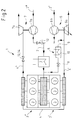
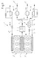
- Figure 1 shows a first embodiment of the supercharged internal combustion engine 1 using the example of a six-cylinder V-engine.
- the cylinders 3 of the internal combustion engine 1 are divided into two groups of cylinders 3 ', 3 ", each having a separate exhaust pipe 4', 4", which are in communication with each other 4 and are used to dissipate the hot exhaust gases of the internal combustion engine.
- Two exhaust gas turbochargers 6, 7 connected in parallel are provided, with the first turbine 6 a of the first exhaust gas turbocharger 6 in the first exhaust gas line 4 'of the first cylinder group 3' and the second turbine 7 a of the second exhaust gas turbocharger 7 in the second exhaust gas line 4 "of the second cylinder group 3 "is arranged.
- the compressors 6b, 7b associated with these turbines 6a, 7a are likewise arranged in separate intake lines 2 ', 2 ", which converge to form a total intake line 2 downstream of the compressors 6b, 7b and serve to supply the internal combustion engine 1 with fresh air or fresh mixture.
- a charge air cooler 5 Downstream of the compressors 6b, 7b, a charge air cooler 5 is arranged in the Puransaugtechnisch 2.
- the charge air cooler 5 lowers the air temperature and thus increases the density of the air, thereby contributing to a better filling of the combustion chamber with air.
- both the turbine 6a of the first exhaust gas turbocharger 6 and the turbine 7a of the second exhaust gas turbocharger 7 have a variable turbine geometry (VTG - indicated by the arrow) which, by adjusting the impeller blades, continuously adapts the turbine geometry allows the current exhaust gas mass flow. This increases in particular the quality and flexibility of charging.
- the compressors 6b, 7b may have a fixed geometry or may also be designed with a variable geometry.
- a variable geometry is advantageous if the corresponding turbine 6a, 7a has a variable turbine geometry and the compressor geometry is continuously tuned to the turbine geometry.
- VVG variable compressor geometry
- the compressors 6b, 7b may also be equipped with a line 15 for charge air blow-off. This is indicated by way of example in FIG. 1 for the second compressor 7b (shown by dashed lines). Downstream of the second compressor, a bypass line 15 branches off from the intake line 2 "assigned to this compressor 7b. A shut-off element 16, which can also be used to adjust the boost pressure, is arranged in the bypass line 15.
- bypass line 15 bypassing the compressor 7b of the switchable exhaust-gas turbocharger 7 is particularly helpful, in particular when starting the switchable exhaust-gas turbocharger 7 in order to avoid pumping of the compressor 7b
- the first and / or the second compressor of the embodiments according to FIGS 2 to 9 can be equipped accordingly with a bypass or blow-off line.
- the internal combustion engine 1 shown in Figure 1 is equipped with an exhaust gas recirculation 8.
- a line 9 for exhaust gas recirculation 8 is provided, which branches off upstream of the first turbine 6a from the first exhaust gas line 4 'assigned to this first turbine 6a and opens into the total intake line 2.
- the line 9 opens to the exhaust gas recirculation 8 downstream of the charge air cooler 5 in the Rescueansaug effet 2. In this way, the exhaust stream is not passed through the intercooler 5 and can not pollute this cooler 5.
- an additional radiator 10 is provided, which lowers the temperature of the hot exhaust gas stream. Also in this line 9, a shut-off element 11 is arranged to control the exhaust gas recirculation rate.
- one of the two turbines 7a is designed as a switchable turbine 7a, wherein means 12 are provided with which the size of the exhaust gas mass flow, which is guided through this turbine 7a, can be controlled.
- the second turbine 7a which has a variable geometry, serves as a switchable turbine 7a and at the same time forms the means 12 for controlling the exhaust gas mass flow through this switchable turbine 7a.
- the turbine 7a By adjusting the turbine 7a in such a way that the turbine cross-section is reduced, the exhaust gas mass flow passed through the turbine 7a is reduced. At the same time, the exhaust back pressure in the exhaust system increases, which is to be regarded as advantageous with regard to the exhaust gas recirculation 8 and in particular with regard to high EGR rates.
- the exhaust gas mass flow through the first turbine 6a also increases as a result of the increased exhaust gas counterpressure, so that this turbine 6a provides the first compressor 6b with more power for compressing the fresh air, which has an advantageous effect on the generation of sufficiently high boost pressures.
- the second compressor 7b which is assigned to the switchable turbine 7a, can be equipped with a variable compressor geometry (VVG).
- VVG variable compressor geometry
- the geometry of the compressor 7b is then adjusted in the direction of the closed position, whereby the compressor 7b is preferably set to its smallest flow cross section.
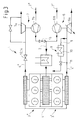
- Figure 2 shows schematically a second embodiment of the supercharged internal combustion engine 1. Only the differences from the embodiment shown in Figure 1 will be discussed, for which reason reference is otherwise made to Figure 1. For the same components, the same reference numerals have been used.
- the second turbine 7a is provided with a fixed d. H. invariable turbine geometry executed.
- VFG variable geometry turbine
- a control is eliminated in principle here. On the whole, this embodiment has particular cost advantages.
- the second turbine 7a again forms the switchable turbine 7a. But since it has no variable turbine geometry, means 12 must be provided, with which the size of the exhaust gas mass flow is controlled by the second turbine 7a.
- a separate shut-off element 14 is provided downstream of the second turbine 7a in the second exhaust gas line 4.
- the flow cross-section of the second exhaust gas line 4 "is steplessly changed or completely opened or completely closed in the context of a two-stage circuit. A reduction of the flow cross-section reduces the exhaust gas mass flow guided by the switchable turbine 7a and at the same time increases the exhaust gas counterpressure.
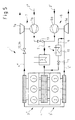
- Figure 3 shows schematically a third embodiment of the supercharged internal combustion engine 1. Only the differences from the embodiment shown in Figure 2 will be discussed, for which reason reference is otherwise made to Figure 2. The same reference numerals have been used for the same components.
- the second turbine 7a is equipped with a bypass line, ie. executed in the waste gate design. This design allows the design of the second turbine 7a to small exhaust gas mass flows.
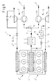
- Figures 4, 5 and 6 show schematically a fourth, a fifth and a sixth embodiment of the supercharged internal combustion engine 1.
- Figure 4 builds on Figure 1, Figure 5 on Figure 2 and Figure 6 on Figure 3 , Only the differences from the embodiments shown in Figures 1, 2 and 3 will be discussed, for which reason reference is otherwise made to Figures 1, 2 and 3.
- the same reference numerals have been used for the same components.
- the difference of the embodiments is that the first turbine 6a of the internal combustion engine 1 with a fixed d. H. invariable turbine geometry is executed. In contrast to a variable geometry turbine (VTG), there is no need for a controller. On the whole, this embodiment has particular cost advantages.
- FIGS. 7, 8 and 9 schematically show a seventh, an eighth and a ninth embodiment of the supercharged internal combustion engine 1.
- FIG. 7 is based on FIG. 1, FIG. 8 on FIG. 2 and FIG. 9 on FIG , It is only the differences to the embodiments shown in Figures 1, 2 and 3 are discussed, which is why otherwise reference is made to Figures 1, 2 and 3. For the same components, the same reference numerals have been used.
- the first turbine 6a of the internal combustion engine 1 is designed as a waste gate turbine.
- the waste gate turbine 6a has a bypass line bypassing the turbine 6a for purposes of exhaust gas discharge, which is a feature of this particular turbine design.
- the turbine 6a is designed for small exhaust gas flows, which significantly improves the quality of the charge in the partial load range. With increasing exhaust gas flow, a larger proportion of the exhaust gas is passed over the bypass line to the turbine 6a over. To control the Abgasabblasung a shut-off is provided in the bypass line.
Landscapes
- Engineering & Computer Science (AREA)
- Chemical & Material Sciences (AREA)
- Combustion & Propulsion (AREA)
- Mechanical Engineering (AREA)
- General Engineering & Computer Science (AREA)
- Supercharger (AREA)
Priority Applications (2)
| Application Number | Priority Date | Filing Date | Title |
|---|---|---|---|
| EP04104583A EP1640595A1 (fr) | 2004-09-22 | 2004-09-22 | Moteur à combustion interne à suralimentation et procédé pour faire fonctionner un tel moteur à combustion interne |
| US11/232,531 US20060059909A1 (en) | 2004-09-22 | 2005-09-22 | Supercharged internal combustion engine |
Applications Claiming Priority (1)
| Application Number | Priority Date | Filing Date | Title |
|---|---|---|---|
| EP04104583A EP1640595A1 (fr) | 2004-09-22 | 2004-09-22 | Moteur à combustion interne à suralimentation et procédé pour faire fonctionner un tel moteur à combustion interne |
Publications (1)
| Publication Number | Publication Date |
|---|---|
| EP1640595A1 true EP1640595A1 (fr) | 2006-03-29 |
Family
ID=34929597
Family Applications (1)
| Application Number | Title | Priority Date | Filing Date |
|---|---|---|---|
| EP04104583A Withdrawn EP1640595A1 (fr) | 2004-09-22 | 2004-09-22 | Moteur à combustion interne à suralimentation et procédé pour faire fonctionner un tel moteur à combustion interne |
Country Status (2)
| Country | Link |
|---|---|
| US (1) | US20060059909A1 (fr) |
| EP (1) | EP1640595A1 (fr) |
Cited By (6)
| Publication number | Priority date | Publication date | Assignee | Title |
|---|---|---|---|---|
| DE102007028522A1 (de) * | 2007-06-21 | 2008-12-24 | Ford Global Technologies, LLC, Dearborn | Verfahren zum Betreiben einer aufgeladenen Brennkraftmaschine |
| DE102007046655A1 (de) * | 2007-09-28 | 2009-04-09 | Audi Ag | Verfahren zum Betreiben einer Brennkraftmaschine, Brennkraftmaschine |
| DE102008025518A1 (de) * | 2008-05-28 | 2009-12-24 | Ford Global Technologies, LLC, Dearborn | Verbrennungsmotor mit parallel geschalteten sequenziellen Turboladern |
| DE102010036595A1 (de) * | 2010-07-23 | 2012-01-26 | Dr. Ing. H.C. F. Porsche Aktiengesellschaft | Kraftfahrzeug |
| CN105179119A (zh) * | 2015-09-09 | 2015-12-23 | 哈尔滨工程大学 | 一种双涡轮船舶二冲程低速柴油机废气再循环系统 |
| DE102016207344A1 (de) | 2016-04-29 | 2017-11-02 | Ford Global Technologies, Llc | Aufgeladene Brennkraftmaschine mit parallel angeordneten Verdichtern und Abgasrückführung |
Families Citing this family (7)
| Publication number | Priority date | Publication date | Assignee | Title |
|---|---|---|---|---|
| CN101182804B (zh) * | 2007-12-06 | 2010-06-02 | 哈尔滨工程大学 | 高增压柴油机的相继增压和进气可控涡流联合系统 |
| JP5331435B2 (ja) * | 2008-10-07 | 2013-10-30 | ヤンマー株式会社 | エンジン |
| CH699804A1 (de) * | 2008-10-29 | 2010-04-30 | Alstom Technology Ltd | Gasturbinenanlage mit Abgasrückführung sowie Verfahren zum Betrieb einer solchen Anlage. |
| CN102400778A (zh) * | 2011-11-03 | 2012-04-04 | 上海交通大学 | 串并联可调的单涡双压涡轮增压系统 |
| US20140067230A1 (en) * | 2012-09-06 | 2014-03-06 | GM Global Technology Operations LLC | Two-stage turbocharger control systems and methods |
| US9957911B2 (en) * | 2016-02-18 | 2018-05-01 | GM Global Technology Operations LLC | Dedicated exhaust gas recirculation control systems and methods |
| SE542129C2 (en) * | 2018-02-15 | 2020-03-03 | Scania Cv Ab | Compressor Arrangement with two compressors in parallel and a Combustion Engine and a Vehicle comprising such arrangement |
Citations (9)
| Publication number | Priority date | Publication date | Assignee | Title |
|---|---|---|---|---|
| US4249382A (en) * | 1978-05-22 | 1981-02-10 | Caterpillar Tractor Co. | Exhaust gas recirculation system for turbo charged engines |
| JPH055419A (ja) * | 1991-06-28 | 1993-01-14 | Isuzu Motors Ltd | 回転電機付ターボチヤージヤの制御装置 |
| US6079211A (en) * | 1997-08-14 | 2000-06-27 | Turbodyne Systems, Inc. | Two-stage supercharging systems for internal combustion engines |
| US20020116926A1 (en) * | 2000-10-05 | 2002-08-29 | Siegfried Sumser | Exhaust gas turbocharger for an internal combustion engine and a corresponding method |
| EP1302646A2 (fr) * | 2001-10-15 | 2003-04-16 | Nissan Motor Company, Limited | Regulation de moteurs à allumage par compression avec recirculation de gaz d'échappement et compresseurs de suralimentation multiples |
| EP1316698A1 (fr) * | 2001-11-29 | 2003-06-04 | Renault s.a.s. | Dispositif et procédé de suralimentation d'un moteur à combustion interne |
| EP1375868A1 (fr) * | 2002-06-26 | 2004-01-02 | Borg Warner Inc. | Dispositif à frein moteur pour un moteur à combustion interne à suralimentation par turbosoufflante |
| EP1400667A2 (fr) * | 2002-09-19 | 2004-03-24 | Dr.Ing. h.c.F. Porsche Aktiengesellschaft | Moteur à combustion interne suralimenté par turbocompresseur |
| WO2004046519A1 (fr) * | 2002-11-20 | 2004-06-03 | Honeywell International Inc. | Systeme de turbocompression sequentielle et procede de turbocompression sequentielle d'un moteur a combustion interne |
Family Cites Families (4)
| Publication number | Priority date | Publication date | Assignee | Title |
|---|---|---|---|---|
| DE3607698C1 (de) * | 1986-03-08 | 1987-06-19 | Mtu Friedrichshafen Gmbh | Kolbenbrennkraftmaschine mit zweistufiger Aufladung |
| DE4416572C1 (de) * | 1994-05-11 | 1995-04-27 | Daimler Benz Ag | Aufgeladene Brennkraftmaschine |
| DE19827627C2 (de) * | 1998-06-20 | 2000-06-15 | Daimler Chrysler Ag | Verfahren und Vorrichtung zur Regelung einer aufgeladenen Brennkraftmaschine |
| DE19835978C1 (de) * | 1998-08-08 | 1999-11-25 | Daimler Chrysler Ag | Biturboaufgeladene Brennkraftmaschine mit Abgasrückführung |
-
2004
- 2004-09-22 EP EP04104583A patent/EP1640595A1/fr not_active Withdrawn
-
2005
- 2005-09-22 US US11/232,531 patent/US20060059909A1/en not_active Abandoned
Patent Citations (9)
| Publication number | Priority date | Publication date | Assignee | Title |
|---|---|---|---|---|
| US4249382A (en) * | 1978-05-22 | 1981-02-10 | Caterpillar Tractor Co. | Exhaust gas recirculation system for turbo charged engines |
| JPH055419A (ja) * | 1991-06-28 | 1993-01-14 | Isuzu Motors Ltd | 回転電機付ターボチヤージヤの制御装置 |
| US6079211A (en) * | 1997-08-14 | 2000-06-27 | Turbodyne Systems, Inc. | Two-stage supercharging systems for internal combustion engines |
| US20020116926A1 (en) * | 2000-10-05 | 2002-08-29 | Siegfried Sumser | Exhaust gas turbocharger for an internal combustion engine and a corresponding method |
| EP1302646A2 (fr) * | 2001-10-15 | 2003-04-16 | Nissan Motor Company, Limited | Regulation de moteurs à allumage par compression avec recirculation de gaz d'échappement et compresseurs de suralimentation multiples |
| EP1316698A1 (fr) * | 2001-11-29 | 2003-06-04 | Renault s.a.s. | Dispositif et procédé de suralimentation d'un moteur à combustion interne |
| EP1375868A1 (fr) * | 2002-06-26 | 2004-01-02 | Borg Warner Inc. | Dispositif à frein moteur pour un moteur à combustion interne à suralimentation par turbosoufflante |
| EP1400667A2 (fr) * | 2002-09-19 | 2004-03-24 | Dr.Ing. h.c.F. Porsche Aktiengesellschaft | Moteur à combustion interne suralimenté par turbocompresseur |
| WO2004046519A1 (fr) * | 2002-11-20 | 2004-06-03 | Honeywell International Inc. | Systeme de turbocompression sequentielle et procede de turbocompression sequentielle d'un moteur a combustion interne |
Non-Patent Citations (1)
| Title |
|---|
| PATENT ABSTRACTS OF JAPAN vol. 017, no. 271 (M - 1417) 26 May 1993 (1993-05-26) * |
Cited By (8)
| Publication number | Priority date | Publication date | Assignee | Title |
|---|---|---|---|---|
| DE102007028522A1 (de) * | 2007-06-21 | 2008-12-24 | Ford Global Technologies, LLC, Dearborn | Verfahren zum Betreiben einer aufgeladenen Brennkraftmaschine |
| DE102007046655A1 (de) * | 2007-09-28 | 2009-04-09 | Audi Ag | Verfahren zum Betreiben einer Brennkraftmaschine, Brennkraftmaschine |
| DE102007046655B4 (de) * | 2007-09-28 | 2019-01-17 | Audi Ag | Verfahren zum Betreiben einer Brennkraftmaschine |
| DE102008025518A1 (de) * | 2008-05-28 | 2009-12-24 | Ford Global Technologies, LLC, Dearborn | Verbrennungsmotor mit parallel geschalteten sequenziellen Turboladern |
| DE102010036595A1 (de) * | 2010-07-23 | 2012-01-26 | Dr. Ing. H.C. F. Porsche Aktiengesellschaft | Kraftfahrzeug |
| DE102010036595B4 (de) | 2010-07-23 | 2022-05-19 | Dr. Ing. H.C. F. Porsche Aktiengesellschaft | Kraftfahrzeug |
| CN105179119A (zh) * | 2015-09-09 | 2015-12-23 | 哈尔滨工程大学 | 一种双涡轮船舶二冲程低速柴油机废气再循环系统 |
| DE102016207344A1 (de) | 2016-04-29 | 2017-11-02 | Ford Global Technologies, Llc | Aufgeladene Brennkraftmaschine mit parallel angeordneten Verdichtern und Abgasrückführung |
Also Published As
| Publication number | Publication date |
|---|---|
| US20060059909A1 (en) | 2006-03-23 |
Similar Documents
| Publication | Publication Date | Title |
|---|---|---|
| EP1640597B1 (fr) | Moteur à combustion interne à suralimentation et procédé pour faire fonctionnner un tel moteur à combustion interne | |
| EP1640596B2 (fr) | Moteur à combustion interne à suralimentation et procédé pour faire fonctionnner un tel moteur à combustion interne | |
| DE102011084782B4 (de) | Verfahren zum Betreiben einer aufgeladenen Brennkraftmaschine mit Abgasrückführung | |
| EP1640598A1 (fr) | Moteur à combustion interne à suralimentation et procédé pour améliorer les émissions d'un moteur à combustion interne | |
| EP1766209A1 (fr) | Moteur a combustion interne pourvu d'une turbosoufflante a gaz d'echappement | |
| EP1640594A1 (fr) | Moteur turbocompressé et méthode de modification de débit des gaz d'échappement recirculés dans un moteur turbocompressé. | |
| DE102013215574A1 (de) | Aufgeladene Brennkraftmaschine mit Abgasnachbehandlung und Verfahren zum Betreiben einer derartigen Brennkraftmaschine | |
| EP1640595A1 (fr) | Moteur à combustion interne à suralimentation et procédé pour faire fonctionner un tel moteur à combustion interne | |
| DE102007052899A1 (de) | Aufgeladene Brennkraftmaschine und Verfahren zum Betreiben einer derartigen Brennkraftmaschine | |
| DE102007028522A1 (de) | Verfahren zum Betreiben einer aufgeladenen Brennkraftmaschine | |
| EP2058485B1 (fr) | Moteur à combustion interne chargé et procédé de fonctionnement d'un tel moteur à combustion interne | |
| WO2008155268A1 (fr) | Moteur à combustion interne avec turbocompression à deux étages et catalyseur d'oxydation | |
| DE102014221331A1 (de) | Verfahren zum Betreiben einer aufgeladenen Brennkraftmaschine und Brennkraftmaschine zur Durchführung eines derartigen Verfahrens umfassend eine variable Turbine | |
| DE102014211127B4 (de) | Aufgeladene Brennkraftmaschine mit in Reihe angeordneten Abgasturboladern und Abgasrückführung und Verfahren zum Betreiben einer derartigen Brennkraftmaschine | |
| DE102015207539B4 (de) | Abgasturboaufgeladene Brennkraftmaschine mit Teilabschaltung und parallel angeordneten Turbinen und Verfahren zum Betreiben einer derartigen Brennkraftmaschine | |
| EP1777387A1 (fr) | Moteur à combustion interne suralimenté et procédé de commande d'un tel moteur | |
| DE202015103551U1 (de) | Abgasturboaufgeladene Brennkraftmaschine mit Teilabschaltung und Zusatzverdichter | |
| EP2058486B1 (fr) | Moteur à combustion interne suralimenté et procédé de fonctionnement d'un tel moteur à combustion interne | |
| DE202014104419U1 (de) | Aufgeladene Brennkraftmaschine mit in Reihe angeordneten Abgasturboladern | |
| DE102014218345A1 (de) | Aufgeladene Brennkraftmaschine mit in Reihe angeordneten Abgasturboladern | |
| WO2013083211A1 (fr) | Machine à combustion interne, en particulier pour un véhicule automobile | |
| DE102017212065B4 (de) | Aufgeladene Brennkraftmaschine mit parallel angeordneten Turbinen und Verfahren zum Betreiben einer derartigen Brennkraftmaschine | |
| DE202014102710U1 (de) | Aufgeladene Brennkraftmaschine mit in Reihe angeordneten Abgasturboladern | |
| DE102015211228A1 (de) | Abgasturboaufgeladene Brennkraftmaschine mit Teilabschaltung und Zusatzverdichter und Verfahren zum Betreiben einer derartigen Brennkraftmaschine | |
| DE202015102241U1 (de) | Zweistufig aufladbare Brennkraftmaschine mit Abgasnachbehandlung |
Legal Events
| Date | Code | Title | Description |
|---|---|---|---|
| PUAI | Public reference made under article 153(3) epc to a published international application that has entered the european phase |
Free format text: ORIGINAL CODE: 0009012 |
|
| AK | Designated contracting states |
Kind code of ref document: A1 Designated state(s): AT BE BG CH CY CZ DE DK EE ES FI FR GB GR HU IE IT LI LU MC NL PL PT RO SE SI SK TR |
|
| AX | Request for extension of the european patent |
Extension state: AL HR LT LV MK |
|
| 17P | Request for examination filed |
Effective date: 20060929 |
|
| AKX | Designation fees paid |
Designated state(s): DE FR GB |
|
| 17Q | First examination report despatched |
Effective date: 20070306 |
|
| R17C | First examination report despatched (corrected) |
Effective date: 20070309 |
|
| STAA | Information on the status of an ep patent application or granted ep patent |
Free format text: STATUS: THE APPLICATION IS DEEMED TO BE WITHDRAWN |
|
| 18D | Application deemed to be withdrawn |
Effective date: 20070720 |