EP1640678A2 - Kombinierte Kühl- und Vakuumerzeugervorrichtung - Google Patents
Kombinierte Kühl- und Vakuumerzeugervorrichtung Download PDFInfo
- Publication number
- EP1640678A2 EP1640678A2 EP05108204A EP05108204A EP1640678A2 EP 1640678 A2 EP1640678 A2 EP 1640678A2 EP 05108204 A EP05108204 A EP 05108204A EP 05108204 A EP05108204 A EP 05108204A EP 1640678 A2 EP1640678 A2 EP 1640678A2
- Authority
- EP
- European Patent Office
- Prior art keywords
- refrigerating
- vacuum
- combined
- generating apparatus
- pressure side
- Prior art date
- Legal status (The legal status is an assumption and is not a legal conclusion. Google has not performed a legal analysis and makes no representation as to the accuracy of the status listed.)
- Granted
Links
Images

Classifications
-
- F—MECHANICAL ENGINEERING; LIGHTING; HEATING; WEAPONS; BLASTING
- F25—REFRIGERATION OR COOLING; COMBINED HEATING AND REFRIGERATION SYSTEMS; HEAT PUMP SYSTEMS; MANUFACTURE OR STORAGE OF ICE; LIQUEFACTION SOLIDIFICATION OF GASES
- F25D—REFRIGERATORS; COLD ROOMS; ICE-BOXES; COOLING OR FREEZING APPARATUS NOT OTHERWISE PROVIDED FOR
- F25D17/00—Arrangements for circulating cooling fluids; Arrangements for circulating gas, e.g. air, within refrigerated spaces
- F25D17/04—Arrangements for circulating cooling fluids; Arrangements for circulating gas, e.g. air, within refrigerated spaces for circulating air, e.g. by convection
- F25D17/042—Air treating means within refrigerated spaces
-
- F—MECHANICAL ENGINEERING; LIGHTING; HEATING; WEAPONS; BLASTING
- F25—REFRIGERATION OR COOLING; COMBINED HEATING AND REFRIGERATION SYSTEMS; HEAT PUMP SYSTEMS; MANUFACTURE OR STORAGE OF ICE; LIQUEFACTION SOLIDIFICATION OF GASES
- F25D—REFRIGERATORS; COLD ROOMS; ICE-BOXES; COOLING OR FREEZING APPARATUS NOT OTHERWISE PROVIDED FOR
- F25D2317/00—Details or arrangements for circulating cooling fluids; Details or arrangements for circulating gas, e.g. air, within refrigerated spaces, not provided for in other groups of this subclass
- F25D2317/04—Treating air flowing to refrigeration compartments
- F25D2317/043—Treating air flowing to refrigeration compartments by creating a vacuum in a storage compartment
Definitions
- the present invention relates to a combined refrigerating and vacuum-generating apparatus according to the preamble of claim 1.
- the task of the compressor is to compress a refrigerating fluid, typically R134a or R600a, which thus reaches a high pressure, and send it in gaseous state to the condenser, wherein the refrigerating fluid condenses and becomes a high-pressure liquid.
- a refrigerating fluid typically R134a or R600a
- the high-pressure refrigerating fluid flows through an expansion unit, which is a component installed between the condenser and the evaporator assembly of the refrigerating circuit, having the function of causing a sharp pressure drop in the refrigerating fluid.
- the expansion unit therefore acts as a pressure differential; the presence of a pressure differential in a refrigerating circuit is very important, because it produces a change of the refrigerating fluid boiling point. Without this pressure change, the refrigerating circuit would just be a simple container of refrigerating fluid, as said refrigerating fluid would not reduce its temperature drastically, reaching some tens of °C below zero, and therefore no refrigeration would take place.
- the refrigerating fluid exiting the expansion unit which generally consists of a small tube called "capillary"
- the evaporator which runs within the walls of the refrigerating apparatus in order to absorb heat from within the cell to be cooled. Having absorbed heat, the refrigerating fluid evaporates and returns to the gaseous state; this allows to obtain the refrigerating process within the refrigerating apparatus.
- the refrigerating fluid being in gaseous state, is subsequently aspirated by the compressor, so as to repeat the refrigeration cycle.
- Another food preservation technique is also known, which consists in placing the food in special containers wherein vacuum is generated in order to reduce the chemical processes and biological activities due to lack of oxygen, thereby slowing down food deterioration.
- the vacuum technique allows to achieve good preservation results, on condition that the optimum vacuum level is provided.
- the generation of vacuum inside food containers takes place in a known way, in particular by using a vacuum- generating circuit comprising a motor, a pump and a duct being connected to the food container.
- a vacuum- generating circuit comprising a motor, a pump and a duct being connected to the food container.
- the vacuum pump When the motor is turned on, the vacuum pump performs a suction action which, through the connection duct, sucks the air being present inside the container, thus generating vacuum therein.
- refrigerating apparatuses in particular refrigerators, freezers or similar apparatuses, are fitted with a refrigerating circuit for refrigeration plus a circuit for generating vacuum inside food containers.
- the refrigerating circuit and the vacuum-generating circuit are separate. Therefore, said refrigerating apparatus have some drawbacks, like the large number of components making up the refrigerating circuit and the vacuum-generating circuit; inevitably, such a complexity translates into higher costs.
- the refrigerating apparatuses known in the art employ a vacuum pump connected to its own motor being separated from the refrigerating circuit and supplied by the electric line as well.
- the present invention aims at eliminating the above-mentioned drawbacks and at providing a combined refrigerating and vacuum-generating apparatus, in particular a refrigerator or a freezer, having an improved and different construction with respect to known solutions.
- the main object of the present invention is to provide a combined refrigerating and vacuum-generating apparatus being fitted with economical and effective means for generating vacuum inside food containers.
- a further object of the present invention is to provide a combined refrigerating and vacuum-generating apparatus which, at the price of a reasonable electric energy consumption, offers very good performance.
- the present invention provides a combined refrigerating and vacuum-generating apparatus incorporating the features of the annexed claims.
- Fig. 1 shows a basic diagram of a combined refrigerating and vacuum-generating apparatus according to the invention.
- Said diagram illustrates a refrigerating circuit of a refrigerating apparatus; said refrigerating circuit comprises a compressor 1, a condenser 2, an expansion unit 5 and an evaporator 6.
- the compressor 1 is powered through an electric line, which can be closed through a switch (not shown in the illustrations, being it of a known type), and is controlled by a thermostat 9, which controls the temperature inside the refrigerating apparatus.
- the condenser 2 may be of any known type being usable in household refrigerating apparatuses, in particular it may be an air-cooled, static, finned-battery and/or ventilated by means of a fan not shown in the illustration.
- the expansion unit 5 consists of a capillary, i.e. a thin duct being some meters long; said capillary may nonetheless be replaced with any other type of expansion unit known in the art.
- the expansion unit 5 allows to obtain a sharp pressure drop in the refrigerating fluid being present in the refrigerating circuit and to dose the refrigerating fluid entering the evaporator 6; it can be easily understood that, if the refrigerating apparatus has more than one refrigerating compartment, the refrigerating circuit will comprise a plurality of evaporators 6 according to a known method.
- the refrigerating circuit also comprises a filter 3, in particular being located upstream the expansion unit 5, adapted to trap any impurity being present in the refrigerating circuit, so as to prevent the expansion unit 5 from being clogged.
- the refrigerating circuit is divided into a high-pressure side AP, i.e. a set of components wherein the refrigerating fluid is at high pressure, and a low-pressure side BP, i.e. a set of components wherein the refrigerating fluid is at low pressure;
- the high-pressure side AP begins at the outlet of the compressor 1, comprises the condenser 2 and reaches the inlet of the expansion unit 5.
- the low-pressure side BP begins at the outlet of the expansion unit 5, comprises the evaporator 6 and reaches the inlet of the compressor 1.
- the refrigerating circuit also comprises a first valve 4, being located on the high-pressure side AP of the refrigerating circuit, in particular downstream the condenser 2, and a second valve 7, being located on the low-pressure side BP of the refrigerating circuit, in particular downstream the evaporator 6.
- the first valve 4 allows to close the refrigerating circuit, thereby preventing the refrigerating fluid from flowing from the high-pressure side AP to the low-pressure side BP.
- the second valve 7 allows to connect vacuum-generating means to the low-pressure side BP of the refrigerating circuit; in the representation of Fig. 1, the vacuum-generating means comprise a pump 10, being preferably a reciprocating pump, which may be connected to a container 13 through a duct 11 and a connection element 12.
- the vacuum-generating means comprise a pump 10, being preferably a reciprocating pump, which may be connected to a container 13 through a duct 11 and a connection element 12.
- current refrigerating apparatuses comprise an electronic control system adapted to control the operation of the household appliance and of its various parts, which may comprise a control panel which the user can operate.
- the compressor 1, the first valve 4, the second valve 7 and the thermostat 9 are controlled by an electronic control system 8 of the refrigerating apparatus, in the example of Fig. 1 said electronic control system 8 consisting of an electronic control board; moreover, said electronic control system 8 is capable of controlling the compressor 1 independently of the state of the thermostat 9.
- the container 13 consists of a hermetically sealed vessel adapted to be housed in a compartment of the refrigerating apparatus; said container 13 is also fitted with an opening adapted to be closed by a valve, in particular a mechanic valve (not shown in the illustrations), which allows to keep the vacuum inside the container 13.
- a valve in particular a mechanic valve (not shown in the illustrations), which allows to keep the vacuum inside the container 13.
- connection element 12 may consist of, for example, a plastic spout; in any case, the connection element 12 is made in such a way as to connect the container 13 to the duct 11, and is located in a compartment of the refrigerating apparatus, preferably in an inner wall of said apparatus.
- connection element 12 and the container 13 may also be provided with sealing means, e.g. gaskets.
- the duct 11 comprises a normally closed valve 14; when said valve 14 is opened, e.g. by operating a push-button (not shown in the illustrations) of the refrigerating apparatus, air enters the duct 11 in order to re-establish the atmospheric pressure within the duct 11, thereby facilitating the removal of the container 13 from the connection element 12.
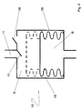
- Fig. 2 shows a schematic section of the pump 10.
- Said pump 10 has a body 15, in particular having a cylindrical shape, it being hermetically divided on the inside into a first cavity A and a second cavity B by a movable element 16, in particular a bellows; the volumes and pressures of the first cavity A and of the second cavity B vary depending on the deformation of the movable element 16.
- the first cavity A is connected to the duct 11 through a valve 17 and to the atmosphere through a valve 18; the second cavity B is connected to the low-pressure side BP of the refrigerating circuit CR through the valve 7.
- the valves 17 and 18 are mechanic valves opening and closing depending on the pressure being present within the first cavity A.
- the valve 17 opens when in the first cavity A there is a pressure which is lower than that being present within the duct 11, and closes when in the first cavity A there is a pressure being higher than that being present within the duct 11; vice versa, the valve 18 opens when in the first cavity A there is a pressure being higher that the atmospheric pressure, and closes when in the first cavity A there is a pressure being lower that the atmospheric pressure.
- the combined refrigerating and vacuum-generating apparatus according to the present invention capable of generating vacuum inside the food container 13, operates as follows.
- the refrigerating circuit of the refrigerating apparatus according to the present invention can operate in two modes; a first refrigerating mode and a second vacuum-generating mode.
- the compressor 1 When the refrigerating circuit of the refrigerating apparatus is operating in the refrigerating mode, the compressor 1 aspirates the refrigerating fluid from the low-pressure side BP and delivers it, at high pressure, to the high-pressure side AP and into the condenser 2, wherein said refrigerating fluid condenses and cools down. After having passed through the filter 3 and the first valve 4, the refrigerating fluid flows through the expansion unit 5 and enters at low pressure the low-pressure side BP of the refrigerating circuit.
- the refrigerating fluid flows through the evaporator 6, which consists of a system of pipes being arranged as a coil running mostly within the walls of the refrigerating appliance and then returning to the compressor 1; when it flows through the evaporator 6, the refrigerating fluid evaporates, thereby cooling the compartments of the refrigerating apparatus.
- the evaporator 6 consists of a system of pipes being arranged as a coil running mostly within the walls of the refrigerating appliance and then returning to the compressor 1; when it flows through the evaporator 6, the refrigerating fluid evaporates, thereby cooling the compartments of the refrigerating apparatus.
- the electronic control system 8 keeps the first valve 4 open and the second valve 7 closed; in this situation, therefore, the vacuum-generating means, in particular the pump 10, are not connected to the low-pressure side BP of the refrigerating circuit CR, and the refrigerating apparatus performs its usual refrigeration cycles for food cooling.
- a user wants to generate vacuum inside the container 13, he/she connects the container 13 to the connection element 12 and then operates a control, e.g. a push-button (not shown in the illustrations), which allows the electronic control system 8 to generate signals adapted:
- the pressure in the low-pressure side BP drops; since the second valve 7 is open, the movable element 16 of the pump 10 moves downward. In such a situation, the volume of the first cavity A increases, whereas the pressure within said first cavity A decreases.
- This pressure reduction in the first cavity A causes the valve 17 to open and the valve 18 to close; since the valve 17 connects the first cavity A to the duct 11, and since the container 13 is connected to the connection element 12, air is aspirated from the container 13 and vacuum is generated therein.
- the electronic control system 8 When the movable element 16 has reached the maximum possible contraction, the electronic control system 8 generates signals adapted to:
- the electronic control system 8 generates signals adapted to:
- the pressure increase in the second cavity B causes the expansion of the movable element 16 and an increase of the volume of said second cavity B; consequently, the volume of the first cavity A decreases and the pressure in said first cavity A increases.
- This pressure increase in the first cavity A causes the valve 17 to close and the valve 18 to open, thereby connecting the first cavity A to the atmosphere and allowing the flexible element 16 to return to its original configuration, indicated in Fig. 2 with a dashed line.
- the refrigerating fluid After having flowed through the expansion unit 5 and to the low-pressure side BP, the refrigerating fluid enters the evaporator 6 and generates a refrigerating apparatus cooling process, even if the compressor 1 is off; this allows to compensate the electric energy used for activating the compressor 1 for the purpose of generating vacuum inside the container 13.
- the movable element 16 may have a structure being similar to that employed in mechanic thermostats, i.e. a helical element being covered with a metal sheath.
- the dimensions of the pump 10 and of the movable element 16 may vary, in particular depending on the structure and/or the compartments of the refrigerating apparatus, e.g. to avoid taking up too much room inside the refrigerating apparatus. It is likely that, if the pump 10 and the movable element 16 are small, a single activation of the movable element 16 is not enough to generate the vacuum degree desired by the user inside the container 13; in these cases, it will however suffice to repeat the vacuum generation cycle inside the container 13 several times, until the vacuum degree inside the container 13 is as required by the user.
- the operation of the refrigerating apparatus being the object of the present invention may therefore be schematized from the combined refrigeration and vacuum generation method by using a refrigerating apparatus comprising a refrigerating circuit it being divided into a high-pressure side and a low-pressure side, and means for generating vacuum inside a container, being coupled to the low-pressure side of the refrigerating circuit, wherein said refrigerating circuit performs the usual refrigeration cycles for cooling the refrigerating apparatus, with at least one cycle for generating vacuum in a container being performed in between.
- the refrigerating circuit may performs several consecutive vacuum generation cycles in order to generate vacuum inside the same container.
- connection of the vacuum-generating means to the low-pressure side of the refrigerating circuit allows to exploit the pressure differential being present within said refrigerating circuit in order to generate vacuum inside the container, in that the pump utilizes the cyclic pressure variations of the refrigerating fluid within the refrigerating circuit.
- a further advantage of the present invention is represented by the use of the compressor of the refrigerating circuit not only for circulating the refrigerating fluid within the refrigerating circuit, but also for generating vacuum inside the container; this inevitably translates into a considerable energy saving, also taking into account that the cooling phase next to the phase for generating vacuum inside the container takes place with the compressor being turned off, i.e. without said compressor drawing electric energy.
- a further advantage of the present invention is to provide a combined refrigerating and vacuum-generating apparatus fitted with vacuum-generating means which do not require any substantial changes to a typical refrigerating apparatus.
- a further advantage of the apparatus according to the present invention is that the number of components making up the refrigerating circuit and the vacuum-generating means is considerably lower than required by the refrigerating devices of the prior art; the remarkable advantages offered by this solution are therefore apparent as concerns both the costs and the reliability of the entire apparatus.
- the pump valves may be directly controllable by the electronic control system of the refrigerating apparatus.
- This variant would allow to further improve the operation of the combined refrigerating and vacuum-generating apparatus being the object of the present invention, as well as to fully exploit the potentiality of said electronic control system.
Landscapes
- Engineering & Computer Science (AREA)
- Chemical & Material Sciences (AREA)
- Combustion & Propulsion (AREA)
- Physics & Mathematics (AREA)
- Mechanical Engineering (AREA)
- Thermal Sciences (AREA)
- General Engineering & Computer Science (AREA)
- Devices That Are Associated With Refrigeration Equipment (AREA)
- Compressors, Vaccum Pumps And Other Relevant Systems (AREA)
- Cold Air Circulating Systems And Constructional Details In Refrigerators (AREA)
Applications Claiming Priority (1)
| Application Number | Priority Date | Filing Date | Title |
|---|---|---|---|
| IT000623A ITTO20040623A1 (it) | 2004-09-16 | 2004-09-16 | Apparato di refrigerazione e per la creazione combinata del vuoto |
Publications (3)
| Publication Number | Publication Date |
|---|---|
| EP1640678A2 true EP1640678A2 (de) | 2006-03-29 |
| EP1640678A3 EP1640678A3 (de) | 2008-04-02 |
| EP1640678B1 EP1640678B1 (de) | 2009-06-17 |
Family
ID=35432458
Family Applications (1)
| Application Number | Title | Priority Date | Filing Date |
|---|---|---|---|
| EP05108204A Expired - Lifetime EP1640678B1 (de) | 2004-09-16 | 2005-09-07 | Kombinierte Kühl- und Vakuumerzeugervorrichtung |
Country Status (5)
| Country | Link |
|---|---|
| EP (1) | EP1640678B1 (de) |
| AT (1) | ATE434160T1 (de) |
| DE (1) | DE602005014916D1 (de) |
| IT (1) | ITTO20040623A1 (de) |
| RU (1) | RU2369809C2 (de) |
Cited By (1)
| Publication number | Priority date | Publication date | Assignee | Title |
|---|---|---|---|---|
| WO2009000724A1 (de) * | 2007-06-28 | 2008-12-31 | BSH Bosch und Siemens Hausgeräte GmbH | Vakuumfrischhaltesystem mit steuerungsverfahren |
Families Citing this family (1)
| Publication number | Priority date | Publication date | Assignee | Title |
|---|---|---|---|---|
| CN106546053B (zh) * | 2016-12-09 | 2019-12-06 | 青岛海尔股份有限公司 | 冷藏冷冻装置 |
Family Cites Families (5)
| Publication number | Priority date | Publication date | Assignee | Title |
|---|---|---|---|---|
| EP0474326A3 (en) * | 1990-09-07 | 1992-04-08 | S.A.V.A. Societa Per Le Applicazioni Del Vuoto Atmosferico | Preservation housing for perishable products |
| JP2001012837A (ja) * | 1999-06-29 | 2001-01-19 | Matsushita Refrig Co Ltd | 真空冷却装置を備えた冷蔵庫 |
| JP2003004354A (ja) * | 2001-06-26 | 2003-01-08 | Sharp Corp | 冷凍庫 |
| JP2004251598A (ja) * | 2003-02-21 | 2004-09-09 | Toshiba Corp | 冷蔵庫 |
| WO2005093349A1 (en) * | 2004-03-22 | 2005-10-06 | Arcelik Anonim Sirketi | A cooling device and a method for improving insulation |
-
2004
- 2004-09-16 IT IT000623A patent/ITTO20040623A1/it unknown
-
2005
- 2005-09-07 AT AT05108204T patent/ATE434160T1/de not_active IP Right Cessation
- 2005-09-07 DE DE602005014916T patent/DE602005014916D1/de not_active Expired - Fee Related
- 2005-09-07 EP EP05108204A patent/EP1640678B1/de not_active Expired - Lifetime
- 2005-09-15 RU RU2005128902/12A patent/RU2369809C2/ru not_active IP Right Cessation
Cited By (2)
| Publication number | Priority date | Publication date | Assignee | Title |
|---|---|---|---|---|
| WO2009000724A1 (de) * | 2007-06-28 | 2008-12-31 | BSH Bosch und Siemens Hausgeräte GmbH | Vakuumfrischhaltesystem mit steuerungsverfahren |
| RU2470239C2 (ru) * | 2007-06-28 | 2012-12-20 | Бсх Бош Унд Сименс Хаусгерете Гмбх | Вакуумная система хранения и способ управления системой |
Also Published As
| Publication number | Publication date |
|---|---|
| RU2369809C2 (ru) | 2009-10-10 |
| EP1640678B1 (de) | 2009-06-17 |
| DE602005014916D1 (de) | 2009-07-30 |
| EP1640678A3 (de) | 2008-04-02 |
| ATE434160T1 (de) | 2009-07-15 |
| RU2005128902A (ru) | 2007-03-20 |
| ITTO20040623A1 (it) | 2004-12-16 |
Similar Documents
| Publication | Publication Date | Title |
|---|---|---|
| JP6023043B2 (ja) | 冷蔵庫の冷却システムおよび流体圧縮器の吸引システム | |
| EP2307825B1 (de) | Kühlsystem | |
| JPH05223370A (ja) | 冷蔵庫 | |
| CN113286974B (zh) | 用于器具的快速切换多蒸发器系统 | |
| EP1640678B1 (de) | Kombinierte Kühl- und Vakuumerzeugervorrichtung | |
| EP0624763A1 (de) | Verflüssiger mit freiem Abfluss für eine Kälteanlage | |
| JPS6050246B2 (ja) | 冷凍装置 | |
| US7673463B2 (en) | Cooling system methods and apparatus for a refrigeration device | |
| CN113091341A (zh) | 双温制冷系统及制冷装置 | |
| CN220582832U (zh) | 制冷设备 | |
| JP2888093B2 (ja) | 真空冷却装置 | |
| CN114111193A (zh) | 一种冰箱和确定化霜周期时长的方法 | |
| WO2020221183A1 (zh) | 制冷电器和使噪声冲击最小化的方法 | |
| KR0120666Y1 (ko) | 냉장고 | |
| KR200184644Y1 (ko) | 혼합형 김치 냉장고의 냉각 사이클 제어 장치 | |
| KR19990035628A (ko) | 냉장고의 습도조절장치 | |
| KR100198400B1 (ko) | 급속 냉동장치를 지닌 냉장고 | |
| EP3034971A1 (de) | Kühlvorrichtung, insbesondere für den haushaltsgebrauch, und zugehöriges verfahren zur herstellung | |
| JP2006125843A (ja) | 冷却サイクル及び冷蔵庫 | |
| JP2004293978A (ja) | 冷蔵庫 | |
| CN119915047A (zh) | 一种冰箱及其真空抽屉的控制方法 | |
| US20220090842A1 (en) | Refrigerated device with enhanced condensate evaporation | |
| RU45017U1 (ru) | Холодильный агрегат | |
| RU2303210C2 (ru) | Агрегат бытового холодильника | |
| KR0154446B1 (ko) | 냉장고 |
Legal Events
| Date | Code | Title | Description |
|---|---|---|---|
| PUAI | Public reference made under article 153(3) epc to a published international application that has entered the european phase |
Free format text: ORIGINAL CODE: 0009012 |
|
| AK | Designated contracting states |
Kind code of ref document: A2 Designated state(s): AT BE BG CH CY CZ DE DK EE ES FI FR GB GR HU IE IS IT LI LT LU LV MC NL PL PT RO SE SI SK TR |
|
| AX | Request for extension of the european patent |
Extension state: AL BA HR MK YU |
|
| RIN1 | Information on inventor provided before grant (corrected) |
Inventor name: BUEV, ALEXANDER Inventor name: GALKIN, IGOR |
|
| PUAL | Search report despatched |
Free format text: ORIGINAL CODE: 0009013 |
|
| AK | Designated contracting states |
Kind code of ref document: A3 Designated state(s): AT BE BG CH CY CZ DE DK EE ES FI FR GB GR HU IE IS IT LI LT LU LV MC NL PL PT RO SE SI SK TR |
|
| AX | Request for extension of the european patent |
Extension state: AL BA HR MK YU |
|
| 17P | Request for examination filed |
Effective date: 20080916 |
|
| AKX | Designation fees paid |
Designated state(s): AT BE BG CH CY CZ DE DK EE ES FI FR GB GR HU IE IS IT LI LT LU LV MC NL PL PT RO SE SI SK TR |
|
| GRAP | Despatch of communication of intention to grant a patent |
Free format text: ORIGINAL CODE: EPIDOSNIGR1 |
|
| GRAS | Grant fee paid |
Free format text: ORIGINAL CODE: EPIDOSNIGR3 |
|
| GRAA | (expected) grant |
Free format text: ORIGINAL CODE: 0009210 |
|
| AK | Designated contracting states |
Kind code of ref document: B1 Designated state(s): AT BE BG CH CY CZ DE DK EE ES FI FR GB GR HU IE IS IT LI LT LU LV MC NL PL PT RO SE SI SK TR |
|
| REG | Reference to a national code |
Ref country code: GB Ref legal event code: FG4D |
|
| REG | Reference to a national code |
Ref country code: CH Ref legal event code: EP |
|
| REG | Reference to a national code |
Ref country code: IE Ref legal event code: FG4D |
|
| REF | Corresponds to: |
Ref document number: 602005014916 Country of ref document: DE Date of ref document: 20090730 Kind code of ref document: P |
|
| PG25 | Lapsed in a contracting state [announced via postgrant information from national office to epo] |
Ref country code: AT Free format text: LAPSE BECAUSE OF FAILURE TO SUBMIT A TRANSLATION OF THE DESCRIPTION OR TO PAY THE FEE WITHIN THE PRESCRIBED TIME-LIMIT Effective date: 20090617 Ref country code: LT Free format text: LAPSE BECAUSE OF FAILURE TO SUBMIT A TRANSLATION OF THE DESCRIPTION OR TO PAY THE FEE WITHIN THE PRESCRIBED TIME-LIMIT Effective date: 20090617 Ref country code: FI Free format text: LAPSE BECAUSE OF FAILURE TO SUBMIT A TRANSLATION OF THE DESCRIPTION OR TO PAY THE FEE WITHIN THE PRESCRIBED TIME-LIMIT Effective date: 20090617 |
|
| PG25 | Lapsed in a contracting state [announced via postgrant information from national office to epo] |
Ref country code: LV Free format text: LAPSE BECAUSE OF FAILURE TO SUBMIT A TRANSLATION OF THE DESCRIPTION OR TO PAY THE FEE WITHIN THE PRESCRIBED TIME-LIMIT Effective date: 20090617 Ref country code: SI Free format text: LAPSE BECAUSE OF FAILURE TO SUBMIT A TRANSLATION OF THE DESCRIPTION OR TO PAY THE FEE WITHIN THE PRESCRIBED TIME-LIMIT Effective date: 20090617 Ref country code: SE Free format text: LAPSE BECAUSE OF FAILURE TO SUBMIT A TRANSLATION OF THE DESCRIPTION OR TO PAY THE FEE WITHIN THE PRESCRIBED TIME-LIMIT Effective date: 20090917 Ref country code: PL Free format text: LAPSE BECAUSE OF FAILURE TO SUBMIT A TRANSLATION OF THE DESCRIPTION OR TO PAY THE FEE WITHIN THE PRESCRIBED TIME-LIMIT Effective date: 20090617 |
|
| NLV1 | Nl: lapsed or annulled due to failure to fulfill the requirements of art. 29p and 29m of the patents act | ||
| PG25 | Lapsed in a contracting state [announced via postgrant information from national office to epo] |
Ref country code: RO Free format text: LAPSE BECAUSE OF FAILURE TO SUBMIT A TRANSLATION OF THE DESCRIPTION OR TO PAY THE FEE WITHIN THE PRESCRIBED TIME-LIMIT Effective date: 20090617 Ref country code: ES Free format text: LAPSE BECAUSE OF FAILURE TO SUBMIT A TRANSLATION OF THE DESCRIPTION OR TO PAY THE FEE WITHIN THE PRESCRIBED TIME-LIMIT Effective date: 20090928 Ref country code: EE Free format text: LAPSE BECAUSE OF FAILURE TO SUBMIT A TRANSLATION OF THE DESCRIPTION OR TO PAY THE FEE WITHIN THE PRESCRIBED TIME-LIMIT Effective date: 20090617 Ref country code: IS Free format text: LAPSE BECAUSE OF FAILURE TO SUBMIT A TRANSLATION OF THE DESCRIPTION OR TO PAY THE FEE WITHIN THE PRESCRIBED TIME-LIMIT Effective date: 20091017 Ref country code: CZ Free format text: LAPSE BECAUSE OF FAILURE TO SUBMIT A TRANSLATION OF THE DESCRIPTION OR TO PAY THE FEE WITHIN THE PRESCRIBED TIME-LIMIT Effective date: 20090617 |
|
| PG25 | Lapsed in a contracting state [announced via postgrant information from national office to epo] |
Ref country code: SK Free format text: LAPSE BECAUSE OF FAILURE TO SUBMIT A TRANSLATION OF THE DESCRIPTION OR TO PAY THE FEE WITHIN THE PRESCRIBED TIME-LIMIT Effective date: 20090617 Ref country code: NL Free format text: LAPSE BECAUSE OF FAILURE TO SUBMIT A TRANSLATION OF THE DESCRIPTION OR TO PAY THE FEE WITHIN THE PRESCRIBED TIME-LIMIT Effective date: 20090617 Ref country code: BE Free format text: LAPSE BECAUSE OF FAILURE TO SUBMIT A TRANSLATION OF THE DESCRIPTION OR TO PAY THE FEE WITHIN THE PRESCRIBED TIME-LIMIT Effective date: 20090617 |
|
| PG25 | Lapsed in a contracting state [announced via postgrant information from national office to epo] |
Ref country code: PT Free format text: LAPSE BECAUSE OF FAILURE TO SUBMIT A TRANSLATION OF THE DESCRIPTION OR TO PAY THE FEE WITHIN THE PRESCRIBED TIME-LIMIT Effective date: 20091017 Ref country code: BG Free format text: LAPSE BECAUSE OF FAILURE TO SUBMIT A TRANSLATION OF THE DESCRIPTION OR TO PAY THE FEE WITHIN THE PRESCRIBED TIME-LIMIT Effective date: 20090917 |
|
| PLBE | No opposition filed within time limit |
Free format text: ORIGINAL CODE: 0009261 |
|
| STAA | Information on the status of an ep patent application or granted ep patent |
Free format text: STATUS: NO OPPOSITION FILED WITHIN TIME LIMIT |
|
| PG25 | Lapsed in a contracting state [announced via postgrant information from national office to epo] |
Ref country code: MC Free format text: LAPSE BECAUSE OF NON-PAYMENT OF DUE FEES Effective date: 20090930 Ref country code: DK Free format text: LAPSE BECAUSE OF FAILURE TO SUBMIT A TRANSLATION OF THE DESCRIPTION OR TO PAY THE FEE WITHIN THE PRESCRIBED TIME-LIMIT Effective date: 20090617 |
|
| REG | Reference to a national code |
Ref country code: CH Ref legal event code: PL |
|
| 26N | No opposition filed |
Effective date: 20100318 |
|
| GBPC | Gb: european patent ceased through non-payment of renewal fee |
Effective date: 20090917 |
|
| REG | Reference to a national code |
Ref country code: FR Ref legal event code: ST Effective date: 20100531 |
|
| PG25 | Lapsed in a contracting state [announced via postgrant information from national office to epo] |
Ref country code: IE Free format text: LAPSE BECAUSE OF NON-PAYMENT OF DUE FEES Effective date: 20090907 Ref country code: FR Free format text: LAPSE BECAUSE OF NON-PAYMENT OF DUE FEES Effective date: 20090930 Ref country code: DE Free format text: LAPSE BECAUSE OF NON-PAYMENT OF DUE FEES Effective date: 20100401 |
|
| PG25 | Lapsed in a contracting state [announced via postgrant information from national office to epo] |
Ref country code: CH Free format text: LAPSE BECAUSE OF NON-PAYMENT OF DUE FEES Effective date: 20090930 Ref country code: LI Free format text: LAPSE BECAUSE OF NON-PAYMENT OF DUE FEES Effective date: 20090930 Ref country code: GR Free format text: LAPSE BECAUSE OF FAILURE TO SUBMIT A TRANSLATION OF THE DESCRIPTION OR TO PAY THE FEE WITHIN THE PRESCRIBED TIME-LIMIT Effective date: 20090918 |
|
| PG25 | Lapsed in a contracting state [announced via postgrant information from national office to epo] |
Ref country code: GB Free format text: LAPSE BECAUSE OF NON-PAYMENT OF DUE FEES Effective date: 20090917 |
|
| PG25 | Lapsed in a contracting state [announced via postgrant information from national office to epo] |
Ref country code: IT Free format text: LAPSE BECAUSE OF FAILURE TO SUBMIT A TRANSLATION OF THE DESCRIPTION OR TO PAY THE FEE WITHIN THE PRESCRIBED TIME-LIMIT Effective date: 20090617 |
|
| PG25 | Lapsed in a contracting state [announced via postgrant information from national office to epo] |
Ref country code: LU Free format text: LAPSE BECAUSE OF NON-PAYMENT OF DUE FEES Effective date: 20090907 |
|
| PG25 | Lapsed in a contracting state [announced via postgrant information from national office to epo] |
Ref country code: HU Free format text: LAPSE BECAUSE OF FAILURE TO SUBMIT A TRANSLATION OF THE DESCRIPTION OR TO PAY THE FEE WITHIN THE PRESCRIBED TIME-LIMIT Effective date: 20091218 |
|
| PG25 | Lapsed in a contracting state [announced via postgrant information from national office to epo] |
Ref country code: TR Free format text: LAPSE BECAUSE OF FAILURE TO SUBMIT A TRANSLATION OF THE DESCRIPTION OR TO PAY THE FEE WITHIN THE PRESCRIBED TIME-LIMIT Effective date: 20090617 |
|
| PG25 | Lapsed in a contracting state [announced via postgrant information from national office to epo] |
Ref country code: CY Free format text: LAPSE BECAUSE OF FAILURE TO SUBMIT A TRANSLATION OF THE DESCRIPTION OR TO PAY THE FEE WITHIN THE PRESCRIBED TIME-LIMIT Effective date: 20090617 |