EP1641040A2 - Thermisch leitfähige Folie und deren Herstellungsmethode - Google Patents
Thermisch leitfähige Folie und deren Herstellungsmethode Download PDFInfo
- Publication number
- EP1641040A2 EP1641040A2 EP05020238A EP05020238A EP1641040A2 EP 1641040 A2 EP1641040 A2 EP 1641040A2 EP 05020238 A EP05020238 A EP 05020238A EP 05020238 A EP05020238 A EP 05020238A EP 1641040 A2 EP1641040 A2 EP 1641040A2
- Authority
- EP
- European Patent Office
- Prior art keywords
- sheet
- thermally conductive
- thin film
- film
- conductive sheet
- Prior art date
- Legal status (The legal status is an assumption and is not a legal conclusion. Google has not performed a legal analysis and makes no representation as to the accuracy of the status listed.)
- Granted
Links
Images
Classifications
-
- H—ELECTRICITY
- H10—SEMICONDUCTOR DEVICES; ELECTRIC SOLID-STATE DEVICES NOT OTHERWISE PROVIDED FOR
- H10W—GENERIC PACKAGES, INTERCONNECTIONS, CONNECTORS OR OTHER CONSTRUCTIONAL DETAILS OF DEVICES COVERED BY CLASS H10
- H10W40/00—Arrangements for thermal protection or thermal control
- H10W40/20—Arrangements for cooling
- H10W40/25—Arrangements for cooling characterised by their materials
- H10W40/255—Arrangements for cooling characterised by their materials having a laminate or multilayered structure, e.g. direct bond copper [DBC] ceramic substrates
-
- H—ELECTRICITY
- H10—SEMICONDUCTOR DEVICES; ELECTRIC SOLID-STATE DEVICES NOT OTHERWISE PROVIDED FOR
- H10W—GENERIC PACKAGES, INTERCONNECTIONS, CONNECTORS OR OTHER CONSTRUCTIONAL DETAILS OF DEVICES COVERED BY CLASS H10
- H10W40/00—Arrangements for thermal protection or thermal control
- H10W40/01—Manufacture or treatment
- H10W40/03—Manufacture or treatment of arrangements for cooling
- H10W40/037—Assembling together parts thereof
-
- H—ELECTRICITY
- H10—SEMICONDUCTOR DEVICES; ELECTRIC SOLID-STATE DEVICES NOT OTHERWISE PROVIDED FOR
- H10W—GENERIC PACKAGES, INTERCONNECTIONS, CONNECTORS OR OTHER CONSTRUCTIONAL DETAILS OF DEVICES COVERED BY CLASS H10
- H10W40/00—Arrangements for thermal protection or thermal control
- H10W40/20—Arrangements for cooling
- H10W40/25—Arrangements for cooling characterised by their materials
- H10W40/251—Organics
-
- Y—GENERAL TAGGING OF NEW TECHNOLOGICAL DEVELOPMENTS; GENERAL TAGGING OF CROSS-SECTIONAL TECHNOLOGIES SPANNING OVER SEVERAL SECTIONS OF THE IPC; TECHNICAL SUBJECTS COVERED BY FORMER USPC CROSS-REFERENCE ART COLLECTIONS [XRACs] AND DIGESTS
- Y10—TECHNICAL SUBJECTS COVERED BY FORMER USPC
- Y10T—TECHNICAL SUBJECTS COVERED BY FORMER US CLASSIFICATION
- Y10T428/00—Stock material or miscellaneous articles
- Y10T428/31504—Composite [nonstructural laminate]
- Y10T428/31855—Of addition polymer from unsaturated monomers
Definitions
- the present invention relates to thermally conductive sheets that are used when mounting electronic components generating a large amount of heat to the cooling portions of heat sinks, radiators and the like, and to methods for producing such thermally conductive sheets.
- Thermally conductive materials are used when mounting electronic components generating a large amount of heat, such as power transistors and power modules (hereinafter, referred to as "heat-generating electronic components"), to heat sinks, radiators and the like for eliminating gaps between the components and conducting the heat that is generated by the heat-generating electronic components to the heat sinks, the radiators and the like efficiently.
- heat-generating electronic components such as power transistors and power modules
- thermally conductive materials there have been proposed, for example, heat-radiating grease and heat-radiating compounds that are formed by mixing liquid silicone with a metal oxide, and thermally conductive heat-radiating members that are fabricated by mixing silicone rubber with a metal oxide and molding it into a sheet (JP H9-207275A and JP H10-183110A).
- thermoly conductive sheet having high thermal conductivity, good dimensional stability, softness, excellent loading characteristics and resistance to cracking, by using a polymer compound that does not create the possibility that a low molecular weight substance such as a monomer or an oligomer will bleed out, and a method for producing the thermally conductive sheet.
- a thermally conductive sheet according to the present invention is a thermally conductive sheet including, as a main component, an acrylic polymer into which a thermally conductive filler is mixed, wherein an inner layer or one side of the sheet is a solventless, adhesive elastic product, and a cured thin film layer is formed integrally with a surface layer portion on at least one selected from top and bottom surfaces of the sheet.
- a method for producing a thermally conductive sheet according to the present invention is a method for producing a thermally conductive sheet including, as a main component, an acrylic polymer into which a thermally conductive filler is mixed, the method including the steps of: forming a cured thin film material layer wherein a material for a thermally conductive, cured thin film layer is applied uniformly as a thin film onto a surface of at least one selected from a top release film and a bottom release film; providing, when one of the films includes the cured thin film material layer, a release film as the other film; supplying, between the top film and the bottom film, a sheet base material including, as a main component, an acrylic polymer into which a thermally conductive filler is mixed, and molding the sheet base material into a sheet having a predetermined thickness; and thereafter curing only a surface layer portion of the sheet and then removing the films, thereby producing a thermally conductive sheet wherein an inner layer or one side of the sheet is a solventless, adhesive elastic product
- the thermally conductive sheet of the present invention includes, as the main component, an acrylic polymer into which a thermally conductive filler is mixed.
- main component refers to a component that constitutes at least 20 mass% of 100 mass% of the total organic components.
- an inner layer or one side of the thermally conductive sheet of the present invention is a solventless, adhesive elastic product.
- solventless as used herein means that the elastic product is formed without actively using an organic solvent.
- the elastic product may contain moisture in the air adsorbed thereto. Accordingly, when attaching the thermally conductive sheet to a heat-generating product such as an electronic component, the thermally conductive sheet freely can change its shape in the thickness direction so as to be attached to the heat-generating product without any gap, thus achieving high heat conductivity and high heat radiation.
- a cured thin film layer is formed integrally with a surface layer portion on at least one selected from the top and bottom surfaces of the sheet. Accordingly, while the inner layer or one side of the thermally conductive sheet is soft, like dough, the thermally conductive sheet is easy to handle because it has a hard thin film layer as the surface layer.
- the method for producing a thermally conductive sheet according to the present invention provides a thermally conductive sheet of the present invention by attaching a thin layer of the material for a thermally conductive, cured thin film layer onto the surface layer of a soft sheet base material by using a so-called transfer method, and then curing only the surface layer of the above-described sheet.
- the thermally conductive sheet is produced by applying the material for a thermally conductive, cured thin film layer uniformly as a thin film onto a release resin film, supplying, onto the surface on which the above-mentioned material has been applied, a sheet base material including, as the main component, an acrylic polymer into which a thermally conductive filler is mixed, placing the release resin film or the release resin film onto which the thermally conductive, cured thin film layer material is applied uniformly as a thin film, over the sheet base material, and molding the sheet base material into a sheet having a predetermined thickness, and thereafter curing only the surface layer portion of the above-described sheet, and then removing the above-described films.
- the cured thin film layer that is formed integrally with one or both sides of the thermally conductive sheet, or the thermally conductive, cured thin film layer has a thickness in the range from 0.001 mm to 0.50 mm. It is preferable that the thermally conductive sheet has an overall thickness of 0.10 mm to 10 mm. Furthermore, a sheet-like reinforcing material may be embedded near the surface layer portion of one of the top and bottom surfaces, and it is preferable that the thickness of the thermally conductive sheet is larger than that of the sheet-like reinforcing material.
- the present invention provides a thermally conductive sheet including, as the main component, an acrylic polymer into which a thermally conductive filler is mixed, wherein the inner surface or one side of the above-described sheet is a solventless, adhesive elastic product, and a cured thin film layer is formed integrally with the surface layer portion of at least one selected from the top and bottom surfaces of the above-described sheet. Accordingly, it is possible to provide a thermally conductive sheet that does not provide the possibility that a low molecular weight substance such as a monomer or an oligomer will bleed out, while having high thermal conductivity, good dimensional stability, softness, excellent loading characteristics and resistance to cracking, and a method for producing such a thermally conductive sheet.
- the elongation of the product at the time of removal from a release sheet can be reduced significantly, resulting in better handleability.
- the ratio between a modified acrylate and an acrylic monomer, or the ratio between a modified acrylate and an acrylic polymer to a suitable ratio, the sheet will not crack when it is bent.
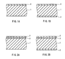
- FIG. 1A is a cross-sectional view showing a thermally conductive sheet according to an embodiment of the present invention.
- the thermally conductive sheet includes a solventless, adhesive elastic product layer 1 including, as the main component, an acrylic polymer into which a thermally conductive filler is mixed, and a cured thin film layer 2 in which a thermally conductive filler is mixed. That is, the cured thin film layer 2 is formed on the surface layer portion of one side of the solventless, adhesive elastic product layer 1.
- FIG. 1B shows an example in which the cured thin film layer 2 is formed on the surface layer portion of both sides of the solventless, adhesive elastic product layer 1.
- FIG. 2A is a cross-sectional view showing a thermally conductive sheet according to another embodiment of the present invention.
- the thermally conductive sheet includes a solventless, adhesive elastic product layer 1 including, as the main component, an acrylic polymer into which a thermally conductive filler is mixed, a sheet-like reinforcing material 3, and a cured thin film layer 2 that is provided as the surface layer of the sheet-like reinforcing material 3 and in which a thermally conductive filler is mixed.
- the sheet-like reinforcing material 3 is embedded in the solventless, adhesive elastic product layer 1.
- FIG. 2B is a cross-sectional view showing a thermally conductive sheet according to yet another embodiment of the present invention.
- the thermally conductive sheet includes a solventless, adhesive elastic product layer 1 including, as the main component, an acrylic polymer into which a thermally conductive filler is mixed, a sheet-like reinforcing material 3, and a cured thin film layer 2 that is provided as the surface layer of the sheet-like reinforcing material 3 and in which a thermally conductive filler is mixed, and a cured thin film layer 2 that is provided on the back side of the solventless, adhesive elastic product layer 1.
- a mesh structure made of, for example, polyester fiber, heat-resistant nylon fiber, aramid fiber or cotton fiber may be used as the sheet-like reinforcing material 3, it is preferable to use polyester fiber or heat-resistant nylon fiber from the view point of heat resistance.
- test sheet having a thickness of 0.5 mm was half-cut precisely into a square shape with a length of 25 mm and a width of 25 mm on a release sheet (note here that ''half-cut'' means only the test sheet formed of a thermally conductive sheet is cut without cutting the release sheet), using a cutting machine. Then, the test sheet was removed by fingers from the release sheet to be collected, and its dimensions were measured precisely to determine the elongation of the test sheet.
- test sheet having a thickness of 3.0 mm was used, and the hardness of the test sheet was measured according to JIS-K7312 (Physical testing methods for molded products of thermosetting polyurethane elastomers).
- Load refers to a compression force at which the sheet deforms when compressing the sheet.
- the purpose of measuring the load was to show the degree of deformation by compression of the sheet when the sheet included the cured thin film. A higher load indicates a higher resistance to deformation.
- a test sheet having a thickness of 3.0 mm was cut into a square shape with a length of 25 mm and a width of 25 mm, and the test sheet was then attached to the center of an aluminum plate (length: 27 mm, width: 27 mm, height: 3 mm) substantially accurately. Then, the test sheet was compressed using a MODEL 310N (compressing load measuring apparatus) manufactured by AIKOH Engineering Co. Ltd. that was provided with a load cell of 200 Kgf at a speed of 5 mm/min until the thickness of the test sheet became 50% of its original thickness, and the load was measured.
- MODEL 310N compressor load measuring apparatus
- the thermal resistance value was measured using a test sheet having a thickness of 0.5 mm.
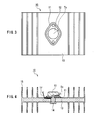
- a thermal resistance value measuring apparatus 10 as shown in FIG. 3 (plan view taken from the top) and FIG. 4 (cross-sectional side view) was used.
- a sample 11 that had been punched into a predetermined shape was prepared, and the sample 11 was inserted and attached between a transistor 12 and a radiator 13 (15 denotes heat-radiating fins).
- the sample 11 was attached by tightening a M3 screw 14 with a predetermined torque (5 kg-cm) using a torque driver. After attaching the sample 11, a DC voltage of 10 V and a current of 2 A (20 W) was applied to the transistor 12.
- test sheet having a thickness of 0.5 mm was wrapped around a metal rod having a diameter of 4 mm, and the presence or absence of cracking was evaluated by determining whether the test sheet cracked.
- the adhesive strength was measured according to JIS-Z-0237 (Testing methods of pressure-sensitive adhesive tapes and sheets).
- This test measured the removability of the sheet when the sheet was deformed by compression.
- a test sheet having a thickness of 3.00 mm was cut into a square shape with a length of 50 mm and a width of 50 mm, and the test sheet then was attached to the center of an aluminum plate (length: 55 mm, width: 55 mm, height: 3 mm) substantially accurately.
- the test sheet was compressed using a MODEL 310N (compressing load measuring apparatus) manufactured by AIKOH Engineering Co. Ltd. that was provided with a load cell of 200 Kgf at a speed of 5 mm/min until the thickness of the test sheet became 50% (1.50 mm) of its original thickness. After releasing the load, the removability was evaluated by determining whether the aluminum plate could be removed manually.
- Urethane acrylate product name: ARONIX M-1200 manufactured by Toagosei Co., Ltd.
- ARONIX M-1200 manufactured by Toagosei Co., Ltd.
- this film is referred to as "film 1".
- a polyester film having a thickness of 0.10 mm that had been surface-treated with a fluorine compound was used as the release film.
- the sheet-like reinforcing material was formed by cutting a polyester fiber mesh (product name: C33 A2-100E11 with a thickness of 0.16 mm, manufactured by UNITIKA GLASS FIBER CO., LTD.) into a predetermined size in such a manner that no grease or dirt would adhere onto the surface of the mesh.
- a polyester fiber mesh product name: C33 A2-100E11 with a thickness of 0.16 mm, manufactured by UNITIKA GLASS FIBER CO., LTD.
- the thermally conductive sheet base material was placed on the reinforcing material, and a sheet of the release film was placed on the sheet base material so as to form a sandwich structure. Thereafter, the whole structure was heated and pressure molded at 120°C for 30 minutes, thereby forming sheets (A2) with thicknesses of 0.5 mm and 3.0 mm that contained the sheet-like reinforcing material and on one side of which the cured thin film layer was formed integrally.
- a sheet of the film 1 was placed on the sheet base material so as to form a sandwich structure. Thereafter, the whole structure was heated and pressure molded at 120°C for 30 minutes, thereby forming sheets (A3) with thicknesses of 0.5 mm and 3.0 mm, on both sides of which the cured thin film layer was formed integrally.
- the thermally conductive sheet base material was placed on the reinforcing material, and a sheet of the film 1 was placed on the sheet base material so as to form a sandwich structure. Thereafter, the whole structure was heated and pressure molded at 120°C for 30 minutes, thereby forming sheets (A4) with thicknesses of 0.5 mm and 3.0 mm that contained the sheet-like reinforcing material and on both sides of which the cured thin film layer was formed integrally.
- Table 1 shows the results on the above-described sheets.
- Table 1 Sample No. A1 A2 A3 A4 B1 Cured thin film one side only one side only both sides both sides not provided Sheet-like reinforcing material not provided provided not provided provided not provided not provided Elongation (mm) 0 0 0 0 0.4 Hardness (Asker C) 25 37 32 40 20 Load (Kgf) 40 50 50 55 25 Thermal resistance value (°C/W) 0.84 0.81 0.90 0.93 0.80
- the sheets on the surface of which the cured thin film layer was formed integrally had good handleability.
- the elongation of the sheets at the time of removal from the release film could be reduced significantly by providing the reinforcing layer on the surface.
- the cured thin film layer was formed from a mixture of a modified acrylate and an acrylic monomer, or a mixture of a modified acrylate and an acrylic polymer, the elongation of the sheet at the time of removal could be reduced to nearly "0". Additionally, the sheet did not crack when it was bent.
- the thermally conductive sheet base material was formed in the same manner as Test ⁇ 1.
- Urethane acrylate (product name: ARONIX M-1200 manufactured by Toagosei Co., Ltd.) was applied uniformly as a thin film with a thickness of 2 ⁇ m using a coating machine onto a polyester film having a thickness of 0.10 mm that had been subjected to a mold release treatment with fluorine, thereby forming a film 2.
- Epoxy acrylate (product name: 8101 manufactured by Japan U-PiCA Company, Ltd.) was applied uniformly as a thin film with a thickness of 2 ⁇ m using a coating machine onto a polyester film having a thickness of 0.10 mm that had been subjected to a mold release treatment with fluorine, thereby forming a film 3.
- Polyester acrylate (product name: M-8060 manufactured by Toagosei Co., Ltd.) was applied uniformly as a thin film with a thickness of 2 ⁇ m using a coating machine onto a polyester film having a thickness of 0.10 mm that had been subjected to a mold release treatment with fluorine, thereby forming a film 4.
- urethane acrylate product name: ARONIXM-1200 manufactured by Toagosei Co., Ltd.
- phenoxy acrylate manufactured by OSAKA ORGANIC CHEMICAL INDUSTRY LTD.
- epoxy acrylate product name: 8101 manufactured by Japan U-PiCA Company, Ltd.
- phenoxy acrylate manufactured by OSAKA ORGANIC CHEMICAL INDUSTRY LTD.
- polyester acrylate product name: M-8060 manufactured by Toagosei Co., Ltd.
- phenoxy acrylate manufactured by OSAKA ORGANIC CHEMICAL INDUSTRY LTD.
- an acrylic polymer product name: JDX-P1020 manufactured by JOHNSON POLYMER CORPORATION
- phenoxy acrylate manufactured by OSAKA ORGANIC CHEMICAL INDUSTRY LTD.
- an acrylic polymer product name: JDX-P1020 manufactured by JOHNSON POLYMER CORPORATION
- urethane acrylate product name: ARONIX M-1200 manufactured by manufactured by Toagosei Co., Ltd.
- a polyester film with a thickness of 0.10 mm that had been surface-treated with a fluorine compound was used as the release film.
- a sheet of the release film was placed on the sheet base material so as to form a sandwich structure. Thereafter, the whole structure was heated and pressure molded at 120°C for 30 minutes, followed by removing the top and bottom films, thereby forming sheets (A5) with thicknesses of 0.5 mm and 3.0 mm, on one side of which the cured thin film layer was formed integrally.
- a sheet of the release film was placed on the sheet base material so as to form a sandwich structure. Thereafter, the whole structure was heated and pressure molded at 120°C for 30 minutes, followed by removing the top and bottom films, thereby forming sheets (A6) with thicknesses of 0.5 mm and 3.0 mm, on one side of which the cured thin film layer was formed integrally.
- a sheet of the release film was placed on the sheet base material so as to form a sandwich structure. Thereafter, the whole structure was heated and pressure molded at 120°C for 30 minutes, followed by removing the top and bottom films, thereby forming sheets (A7) with thicknesses of 0.5 mm and 3.0 mm, on one side of which the cured thin film layer was formed integrally.
- a sheet of the release film was placed on the sheet base material so as to form a sandwich structure. Thereafter, the whole structure was heated and pressure molded at 120°C for 30 minutes, followed by removing the top and bottom films, thereby forming sheets (A8) with thicknesses of 0.5 mm and 3.0 mm, on one side of which the cured thin film layer was formed integrally.
- a sheet of the release film was placed on the sheet base material so as to form a sandwich structure. Thereafter, the whole structure was heated and pressure molded at 120°C for 30 minutes, followed by removing the top and bottom films, thereby forming sheets (A9) with thicknesses of 0.5 mm and 3.0 mm, on one side of which the cured thin film layer was formed integrally.
- a sheet of the release film was placed on the sheet base material so as to form a sandwich structure. Thereafter, the whole structure was heated and pressure molded at 120°C for 30 minutes, followed by removing the top and bottom films, thereby forming sheets (A10) with thicknesses of 0.5 mm and 3.0 mm, on one side of which the cured thin film layer was formed integrally.
- a sheet of the release film was placed on the sheet base material so as to form a sandwich structure. Thereafter, the whole structure was heated and pressure molded at 120°C for 30 minutes, followed by removing the top and bottom films, thereby forming sheets (A11) with thicknesses of 0.5 mm and 3.0 mm, on one side of which the cured thin film layer was formed integrally.
- a sheet of the release film was placed on the sheet base material so as to form a sandwich structure. Thereafter, the whole structure was heated and pressure molded at 120°C for 30 minutes, followed by removing the top and bottom films, thereby forming sheets (A12) with thicknesses of 0.5 mm and 3.0 mm, on one side of which the cured thin film layer was formed integrally.
- the cured thin film was formed only from a modified acrylate. Since a modified acrylate includes a large number of functional groups in its molecules, the cross-linking density of the cured thin film layer was higher and the cured thin film cracked easily. However, in the case of the sample Nos. A9 to A12 of Working Example 9 to Working Example 12, an acrylic monomer or an acrylic rubber was added to the modified acrylate to decrease the cross-linking density of the cured thin film layer, so that the cured thin film was imparted with flexibility and thus became more difficult to crack.
- the sample No. B2 of Comparative Example 2 was an example in which the sample was formed only from the thermally conductive sheet base material.
- the sheet of the sample No. B2 of Comparative Example 2 was not desirable since it was elongated and deformed.
- the sheets of the sample Nos. A9 to A12 of Working Example 9 to Working Example 12 deformed in the thickness direction, but not in the longitudinal direction, exhibiting good form stability.
- the thermally conductive sheet base material was formed in the same manner as Test ⁇ 1.
- film 11 to film 14 below were formed.
- urethane acrylate product name: ARONIX M-1200 manufactured by Toagosei Co., Ltd.
- aluminum oxide product name: AL-43L manufactured by SHOWA DENKO K.K.
- iron black 1 part by mass of a curing agent (chemical name: t-Amyl peroxy-2-ethylhexanoate manufactured by Kayaku Akzo Corporation) were mixed sufficiently in a mixer. Then, the mixture was applied uniformly as a thin film with a thickness of 2 ⁇ m using a coating machine onto a polyester film having a thickness of 0.10 mm that had been subjected to a mold release treatment with fluorine, thereby forming a film 11.
- polyester acrylate product name: M-6100 manufactured by Toagosei Co., Ltd.
- aluminum oxide product name: AL-43L manufactured by SHOWA DENKO K.K.
- iron black 1 part by mass of a curing agent (chemical name: t-Amyl peroxy-2-ethylhexanoate manufactured by Kayaku Akzo Corporation) were mixed sufficiently in a mixer. Then, the mixture was applied uniformly as a thin film with a thickness of 2 ⁇ m using a coating machine onto a polyester film having a thickness of 0.10 mm that had been subjected to a mold release treatment with fluorine, thereby forming a film 12.
- the mixture was applied uniformly as a thin film with a thickness of 2 ⁇ m using a coating machine onto a polyester film having a thickness of 0.10 mm that had been subjected to a mold release treatment with fluorine, thereby forming a film 13.
- the mixture was applied uniformly as a thin film with a thickness of 2 ⁇ m using a coating machine onto a polyester film having a thickness of 0.10 mm that had been subjected to a mold release treatment with fluorine, thereby forming a film 14.
- a polyester film having a thickness of 0.10 mm that had been surface-treated with a fluorine compound was used as a film 15.
- the sheet-like reinforcing material was formed by cutting a polyester fiber mesh (product name: C33 A2-100E 11 with a thickness of 0.16 mm, manufactured by UNITIKA GLASS FIBER CO., LTD.) into a predetermined size in such a manner that no grease or dirt would adhere onto the surface of the mesh.
- a polyester fiber mesh product name: C33 A2-100E 11 with a thickness of 0.16 mm, manufactured by UNITIKA GLASS FIBER CO., LTD.
- a polyester film having a thickness of 0.10 mm that had been surface-treated with a fluorine compound was used as the release film.
- the thermally conductive sheet base material was placed on the reinforcing material, and a sheet of the release film was placed further on the sheet base material so as to form a sandwich structure. Thereafter, the whole structure was heated and pressure molded at 120°C for 30 minutes, followed by removing the top and bottom films, thereby forming sheets (A13) with thicknesses of 0.5 mm and 3.0 mm, on one side of which the thermally conductive, cured thin film layer was formed integrally.
- a sheet of the release film was placed on the sheet base material so as to form a sandwich structure. Thereafter, the whole structure was heated and pressure molded at 120°C for 30 minutes, followed by removing the top and bottom films, thereby forming sheets (A14) with thicknesses of 0.5 mm and 3.0 mm, on one side of which the thermally conductive, cured thin film layer was formed integrally.
- the thermally conductive sheet base material was placed on the reinforcing material, and a sheet of the release film was placed further on the sheet base material so as to form a sandwich structure. Thereafter, the whole structure was heated and pressure molded at 120°C for 30 minutes, followed by removing the top and bottom films, thereby forming sheets (A15) with thicknesses of 0.5 mm and 3.0 mm, on one side of which the thermally conductive, cured thin film layer was formed integrally.
- a sheet of the release film was placed on the sheet base material so as to form a sandwich structure. Thereafter, the whole structure was heated and pressure molded at 120°C for 30 minutes, followed by removing the top and bottom films, thereby forming sheets (A16) with thicknesses of 0.5 mm and 3.0 mm, on one side of which the thermally conductive, cured thin film layer was formed integrally.
- the thermally conductive sheet base material was placed on the reinforcing material, and a sheet of the release film was placed further on the sheet base material so as to form a sandwich structure. Thereafter, the whole structure was heated and pressure molded at 120°C for 30 minutes, followed by removing the top and bottom films, thereby forming sheets (A17) with thicknesses of 0.5 mm and 3.0 mm, on one side of which the thermally conductive, cured thin film layer was formed integrally.
- a sheet of the release film was placed on the sheet base material so as to form a sandwich structure. Thereafter, the whole structure was heated and pressure molded at 120°C for 30 minutes, followed by removing the top and bottom films, thereby forming sheets (A18) with thicknesses of 0.5 mm and 3.0 mm, on one side of which the thermally conductive, cured thin film layer was formed integrally.
- the thermally conductive sheet base material was placed on the reinforcing material, and a sheet of the release film was placed further on the sheet base material so as to form a sandwich structure. Thereafter, the whole structure was heated and pressure molded at 120°C for 30 minutes, followed by removing the top and bottom films, thereby forming sheets (A19) with thicknesses of 0.5 mm and 3.0 mm, on one side of which the thermally conductive, cured thin film layer was formed integrally.
- a sheet of the release film was placed on the sheet base material so as to form a sandwich structure. Thereafter, the whole structure was heated and pressure molded at 120°C for 30 minutes, followed by removing the top and bottom films, thereby forming sheets (A20) with thicknesses of 0.5 mm and 3.0 mm, on one side of which the thermally conductive, cured thin film layer was formed integrally.
- the thermally conductive sheet base material was placed on the reinforcing material, and a sheet of the release film was placed further on the sheet base material so as to form a sandwich structure. Thereafter, the whole structure was heated and pressure molded at 120°C for 30 minutes, followed by removing the top and bottom films, thereby forming sheets (B3) with thicknesses of 0.5 mm and 3.0 mm. ,
- a sheet of the release film was placed on the sheet base material so as to form a sandwich structure. Thereafter, the whole structure was heated and pressure molded at 120°C for 30 minutes, followed by removing the top and bottom films, thereby forming sheets (B4) with thicknesses of 0.5 mm and 3.0 mm.
- a sheet of the release film was placed further on the sheet base material so as to form a sandwich structure. Thereafter, the whole structure was heated and pressure molded at 120°C for 30 minutes, followed by removing the top and bottom films, thereby forming sheets (B5) with thicknesses of 0.5 mm and 3.0 mm.
- Tables 3 and 4 show the results on the above-described sheets.
- Table 3 Sample No. A13 A14 A15 A16 A17 A18 A19 A20 Sheet-like reinforcing material provided not provided provided not provided provided not provided Adhesive strength (g/25 mm) 0 0 0 0 0 0 0 0 0 0 Thermal resistance value (°C/W) 0.92 0.99 0.92 0.88 0.90 0.86 0.90 0.86 Removability easy easy easy easy easy easy easy easy easy easy easy easy easy easy easy Table 4 Sample No. B3 B4 B5 B6 Sheet-like reinforcing material provided not provided provided not provided not provided Adhesive strength (g/25 mm) 12 12 0 0 Thermal resistance value (°C /W) 0.38 0.36 0.94 0.92 Removability difficult difficult easy easy easy easy easy easy.
- the adhesive strength of the sample Nos. A13 to 20 of Working Examples 13 to 20 could be reduced to nearly "0" by forming the cured thin film layer. This made it possible to separate a heat-generating electronic component and a radiator readily, even after inserting the thermally conductive film between them. Furthermore, the thermal resistance value (°C/W) was improved even further by providing the cured thin film layer with thermal conductivity.
Landscapes
- Laminated Bodies (AREA)
- Cooling Or The Like Of Semiconductors Or Solid State Devices (AREA)
- Manufacture Of Macromolecular Shaped Articles (AREA)
Applications Claiming Priority (1)
| Application Number | Priority Date | Filing Date | Title |
|---|---|---|---|
| JP2004275968 | 2004-09-22 |
Publications (3)
| Publication Number | Publication Date |
|---|---|
| EP1641040A2 true EP1641040A2 (de) | 2006-03-29 |
| EP1641040A3 EP1641040A3 (de) | 2008-10-22 |
| EP1641040B1 EP1641040B1 (de) | 2018-11-07 |
Family
ID=35482158
Family Applications (1)
| Application Number | Title | Priority Date | Filing Date |
|---|---|---|---|
| EP05020238.1A Expired - Lifetime EP1641040B1 (de) | 2004-09-22 | 2005-09-16 | Thermisch leitfähige Folie und deren Herstellungsmethode |
Country Status (4)
| Country | Link |
|---|---|
| US (1) | US20060063017A1 (de) |
| EP (1) | EP1641040B1 (de) |
| CN (1) | CN100433312C (de) |
| TW (1) | TWI295095B (de) |
Cited By (4)
| Publication number | Priority date | Publication date | Assignee | Title |
|---|---|---|---|---|
| EP2207674A4 (de) * | 2007-11-05 | 2011-02-16 | Laird Technologies Inc | Thermisches zwischenmaterial mit dünnem übertragungsfilm oder metallisierung |
| US8445102B2 (en) | 2007-11-05 | 2013-05-21 | Laird Technologies, Inc. | Thermal interface material with thin transfer film or metallization |
| US20130265721A1 (en) * | 2007-11-05 | 2013-10-10 | Laird Technologies, Inc. | Thermal Interface Materials with Thin Film or Metallization |
| US9627293B2 (en) | 2014-06-04 | 2017-04-18 | Mitsubishi Electric Corporation | Semiconductor device and heat-conductive sheet |
Families Citing this family (8)
| Publication number | Priority date | Publication date | Assignee | Title |
|---|---|---|---|---|
| JP5156511B2 (ja) * | 2008-07-11 | 2013-03-06 | ポリマテック株式会社 | 熱伝導性シート複合体及びその製造方法 |
| JP5740103B2 (ja) * | 2009-10-19 | 2015-06-24 | 日東電工株式会社 | 熱伝導部材、及びそれを用いた組電池装置 |
| KR101524506B1 (ko) * | 2009-12-21 | 2015-06-01 | 생-고뱅 퍼포먼스 플라스틱스 코포레이션 | 열전도성 폼 재료 |
| JP5892734B2 (ja) | 2011-05-02 | 2016-03-23 | スリーエム イノベイティブ プロパティズ カンパニー | 熱伝導性シート |
| JP5766335B2 (ja) * | 2013-07-01 | 2015-08-19 | デクセリアルズ株式会社 | 熱伝導シートの製造方法、熱伝導シート、及び放熱部材 |
| JP6261386B2 (ja) * | 2014-03-04 | 2018-01-17 | デクセリアルズ株式会社 | 多層型熱伝導性シート、多層型熱伝導性シートの製造方法 |
| JP2016082155A (ja) * | 2014-10-21 | 2016-05-16 | 信越化学工業株式会社 | 放熱シート |
| US10825780B2 (en) * | 2016-11-29 | 2020-11-03 | Taiwan Semiconductor Manufacturing Company, Ltd. | Semiconductor device with electromagnetic interference protection and method of manufacture |
Family Cites Families (14)
| Publication number | Priority date | Publication date | Assignee | Title |
|---|---|---|---|---|
| US4685987A (en) * | 1983-09-02 | 1987-08-11 | The Bergquist Company | Method of preparing interfacings of heat sinks with electrical devices |
| US5213868A (en) * | 1991-08-13 | 1993-05-25 | Chomerics, Inc. | Thermally conductive interface materials and methods of using the same |
| US6090484A (en) * | 1995-05-19 | 2000-07-18 | The Bergquist Company | Thermally conductive filled polymer composites for mounting electronic devices and method of application |
| USH1699H (en) * | 1995-10-31 | 1997-12-02 | The United States Of America As Represented By The Secretary Of The Navy | Thermal bond system |
| US6083853A (en) * | 1996-11-06 | 2000-07-04 | Fuji Polymer Industries Co., Ltd. | Formed sheet of thermoconductive silicone gel and method for producing the same |
| CA2273289A1 (en) * | 1996-11-29 | 1998-06-04 | Takao Yoshikawa | Thermally conductive pressure-sensitive adhesive and adhesive sheet containing the same |
| KR20000057373A (ko) * | 1996-12-04 | 2000-09-15 | 가마이 고로 | 열 전도성 감압 접착제, 이의 접착 시트류 및 이를 사용한 전자부품과 방열 부재와의 고정방법 |
| US6432497B2 (en) * | 1997-07-28 | 2002-08-13 | Parker-Hannifin Corporation | Double-side thermally conductive adhesive tape for plastic-packaged electronic components |
| US6391442B1 (en) * | 1999-07-08 | 2002-05-21 | Saint-Gobain Performance Plastics Corporation | Phase change thermal interface material |
| US6644395B1 (en) * | 1999-11-17 | 2003-11-11 | Parker-Hannifin Corporation | Thermal interface material having a zone-coated release linear |
| MXPA03006498A (es) * | 2001-01-22 | 2003-10-15 | Parker Hannifin Corp | Entrecara termica de cambio de fase, de liberacion limpia. |
| JP2004035721A (ja) * | 2002-07-03 | 2004-02-05 | Kanegafuchi Chem Ind Co Ltd | 熱伝導性熱可塑性エラストマー組成物および熱伝導性熱可塑性エラストマーシート |
| US6657297B1 (en) * | 2002-08-15 | 2003-12-02 | The Bergquist Company | Flexible surface layer film for delivery of highly filled or low cross-linked thermally conductive interface pads |
| JP2004031968A (ja) * | 2003-06-30 | 2004-01-29 | Mochida Shoko Kk | 放熱シート及びその製造方法 |
-
2005
- 2005-09-15 US US11/227,496 patent/US20060063017A1/en not_active Abandoned
- 2005-09-15 TW TW94131765A patent/TWI295095B/zh not_active IP Right Cessation
- 2005-09-16 EP EP05020238.1A patent/EP1641040B1/de not_active Expired - Lifetime
- 2005-09-22 CN CNB200510106806XA patent/CN100433312C/zh not_active Expired - Lifetime
Cited By (6)
| Publication number | Priority date | Publication date | Assignee | Title |
|---|---|---|---|---|
| EP2207674A4 (de) * | 2007-11-05 | 2011-02-16 | Laird Technologies Inc | Thermisches zwischenmaterial mit dünnem übertragungsfilm oder metallisierung |
| US8445102B2 (en) | 2007-11-05 | 2013-05-21 | Laird Technologies, Inc. | Thermal interface material with thin transfer film or metallization |
| US8545987B2 (en) | 2007-11-05 | 2013-10-01 | Laird Technologies, Inc. | Thermal interface material with thin transfer film or metallization |
| US20130265721A1 (en) * | 2007-11-05 | 2013-10-10 | Laird Technologies, Inc. | Thermal Interface Materials with Thin Film or Metallization |
| US9795059B2 (en) | 2007-11-05 | 2017-10-17 | Laird Technologies, Inc. | Thermal interface materials with thin film or metallization |
| US9627293B2 (en) | 2014-06-04 | 2017-04-18 | Mitsubishi Electric Corporation | Semiconductor device and heat-conductive sheet |
Also Published As
| Publication number | Publication date |
|---|---|
| US20060063017A1 (en) | 2006-03-23 |
| EP1641040A3 (de) | 2008-10-22 |
| EP1641040B1 (de) | 2018-11-07 |
| TWI295095B (en) | 2008-03-21 |
| CN100433312C (zh) | 2008-11-12 |
| CN1753171A (zh) | 2006-03-29 |
| TW200627612A (en) | 2006-08-01 |
Similar Documents
| Publication | Publication Date | Title |
|---|---|---|
| EP1641040B1 (de) | Thermisch leitfähige Folie und deren Herstellungsmethode | |
| EP1976005A2 (de) | Wärmeleitfähiges Folie und Herstellungsverfahren dafür | |
| EP3018708B1 (de) | Verfahren zur herstellung einer wärmeleitenden folie, wärmeleitende folie und wärmeableitungselement | |
| US6794026B2 (en) | Radiating sheet and PDP panel | |
| CN108461462B (zh) | 导热片的制造方法、导热片及散热部件 | |
| EP3533579A1 (de) | Dreidimensional geformter thermisch leitfähiger formkörper und herstellungsverfahren dafür | |
| US20140374080A1 (en) | Compliant multilayered thermally-conductive interface assemblies | |
| JP5760397B2 (ja) | 熱伝導シート、熱伝導シートの製造方法、及び放熱装置 | |
| KR102722859B1 (ko) | 열전도성 시트 | |
| CN109997423B (zh) | 具有高耐负荷性及高导热性的散热片 | |
| EP2496732A2 (de) | Materialien und verfahren für wärme- und stromleitfähigkeit | |
| CN101277601A (zh) | 积层体 | |
| DE69709978T2 (de) | Wärmeableitende Abstandhalter für elektronische Einrichtungen | |
| JP2012109312A (ja) | 熱伝導シート、熱伝導シートの製造方法、及び放熱装置 | |
| US20250014965A1 (en) | Thermal interface material | |
| EP1274561A1 (de) | Thermisch leitende folie | |
| WO2018078436A1 (ja) | 三次元形状熱伝導性成形体、及びその製造方法 | |
| JP4530283B2 (ja) | 熱伝導性シート及びその製造方法 | |
| JP7847479B2 (ja) | 熱伝導シート及び熱伝導シートの製造方法 | |
| JP4446514B2 (ja) | 熱伝導性シリコーン成形体の放熱部材 | |
| CN116964731A (zh) | 导热性树脂片 | |
| US20240262979A1 (en) | Thermally-conductive sheet and thermally-conductive sheet production method | |
| JP3092699B2 (ja) | 放熱スペーサーとその用途およびシリコーン組成物 | |
| EP4303270A1 (de) | Weiches wärmeleitendes element | |
| JP7712839B2 (ja) | 多層構造体 |
Legal Events
| Date | Code | Title | Description |
|---|---|---|---|
| PUAI | Public reference made under article 153(3) epc to a published international application that has entered the european phase |
Free format text: ORIGINAL CODE: 0009012 |
|
| AK | Designated contracting states |
Kind code of ref document: A2 Designated state(s): AT BE BG CH CY CZ DE DK EE ES FI FR GB GR HU IE IS IT LI LT LU LV MC NL PL PT RO SE SI SK TR |
|
| AX | Request for extension of the european patent |
Extension state: AL BA HR MK YU |
|
| PUAL | Search report despatched |
Free format text: ORIGINAL CODE: 0009013 |
|
| AK | Designated contracting states |
Kind code of ref document: A3 Designated state(s): AT BE BG CH CY CZ DE DK EE ES FI FR GB GR HU IE IS IT LI LT LU LV MC NL PL PT RO SE SI SK TR |
|
| AX | Request for extension of the european patent |
Extension state: AL BA HR MK YU |
|
| 17P | Request for examination filed |
Effective date: 20090113 |
|
| AKX | Designation fees paid |
Designated state(s): DE FR |
|
| 17Q | First examination report despatched |
Effective date: 20100205 |
|
| STAA | Information on the status of an ep patent application or granted ep patent |
Free format text: STATUS: EXAMINATION IS IN PROGRESS |
|
| GRAP | Despatch of communication of intention to grant a patent |
Free format text: ORIGINAL CODE: EPIDOSNIGR1 |
|
| STAA | Information on the status of an ep patent application or granted ep patent |
Free format text: STATUS: GRANT OF PATENT IS INTENDED |
|
| INTG | Intention to grant announced |
Effective date: 20180724 |
|
| GRAS | Grant fee paid |
Free format text: ORIGINAL CODE: EPIDOSNIGR3 |
|
| GRAA | (expected) grant |
Free format text: ORIGINAL CODE: 0009210 |
|
| STAA | Information on the status of an ep patent application or granted ep patent |
Free format text: STATUS: THE PATENT HAS BEEN GRANTED |
|
| AK | Designated contracting states |
Kind code of ref document: B1 Designated state(s): DE FR |
|
| RAP1 | Party data changed (applicant data changed or rights of an application transferred) |
Owner name: FUJI POLYMER INDUSTRIES CO., LTD. |
|
| RIN1 | Information on inventor provided before grant (corrected) |
Inventor name: FUNAHASHI, HAJIME |
|
| REG | Reference to a national code |
Ref country code: DE Ref legal event code: R096 Ref document number: 602005054932 Country of ref document: DE |
|
| REG | Reference to a national code |
Ref country code: DE Ref legal event code: R097 Ref document number: 602005054932 Country of ref document: DE |
|
| PLBE | No opposition filed within time limit |
Free format text: ORIGINAL CODE: 0009261 |
|
| STAA | Information on the status of an ep patent application or granted ep patent |
Free format text: STATUS: NO OPPOSITION FILED WITHIN TIME LIMIT |
|
| 26N | No opposition filed |
Effective date: 20190808 |
|
| PGFP | Annual fee paid to national office [announced via postgrant information from national office to epo] |
Ref country code: DE Payment date: 20240918 Year of fee payment: 20 |
|
| PGFP | Annual fee paid to national office [announced via postgrant information from national office to epo] |
Ref country code: FR Payment date: 20240924 Year of fee payment: 20 |
|
| REG | Reference to a national code |
Ref country code: DE Ref legal event code: R071 Ref document number: 602005054932 Country of ref document: DE |