EP1642036B1 - Plaque destinee a etre appliquee sur des sols, ainsi que sur des murs, plafonds, fa ades ou analogues - Google Patents
Plaque destinee a etre appliquee sur des sols, ainsi que sur des murs, plafonds, fa ades ou analogues Download PDFInfo
- Publication number
- EP1642036B1 EP1642036B1 EP04737369A EP04737369A EP1642036B1 EP 1642036 B1 EP1642036 B1 EP 1642036B1 EP 04737369 A EP04737369 A EP 04737369A EP 04737369 A EP04737369 A EP 04737369A EP 1642036 B1 EP1642036 B1 EP 1642036B1
- Authority
- EP
- European Patent Office
- Prior art keywords
- plate
- elastically deflectable
- shaped carrier
- projection
- recess
- Prior art date
- Legal status (The legal status is an assumption and is not a legal conclusion. Google has not performed a legal analysis and makes no representation as to the accuracy of the status listed.)
- Expired - Lifetime
Links
Images


Classifications
-
- E—FIXED CONSTRUCTIONS
- E01—CONSTRUCTION OF ROADS, RAILWAYS, OR BRIDGES
- E01C—CONSTRUCTION OF, OR SURFACES FOR, ROADS, SPORTS GROUNDS, OR THE LIKE; MACHINES OR AUXILIARY TOOLS FOR CONSTRUCTION OR REPAIR
- E01C5/00—Pavings made of prefabricated single units
- E01C5/22—Pavings made of prefabricated single units made of units composed of a mixture of materials covered by two or more of groups E01C5/008, E01C5/02 - E01C5/20 except embedded reinforcing materials
-
- E—FIXED CONSTRUCTIONS
- E04—BUILDING
- E04F—FINISHING WORK ON BUILDINGS, e.g. STAIRS, FLOORS
- E04F13/00—Coverings or linings, e.g. for walls or ceilings
- E04F13/07—Coverings or linings, e.g. for walls or ceilings composed of covering or lining elements; Sub-structures therefor; Fastening means therefor
- E04F13/08—Coverings or linings, e.g. for walls or ceilings composed of covering or lining elements; Sub-structures therefor; Fastening means therefor composed of a plurality of similar covering or lining elements
-
- E—FIXED CONSTRUCTIONS
- E04—BUILDING
- E04F—FINISHING WORK ON BUILDINGS, e.g. STAIRS, FLOORS
- E04F15/00—Flooring
- E04F15/02—Flooring or floor layers composed of a number of similar elements
-
- F—MECHANICAL ENGINEERING; LIGHTING; HEATING; WEAPONS; BLASTING
- F16—ENGINEERING ELEMENTS AND UNITS; GENERAL MEASURES FOR PRODUCING AND MAINTAINING EFFECTIVE FUNCTIONING OF MACHINES OR INSTALLATIONS; THERMAL INSULATION IN GENERAL
- F16B—DEVICES FOR FASTENING OR SECURING CONSTRUCTIONAL ELEMENTS OR MACHINE PARTS TOGETHER, e.g. NAILS, BOLTS, CIRCLIPS, CLAMPS, CLIPS OR WEDGES; JOINTS OR JOINTING
- F16B5/00—Joining sheets or plates, e.g. panels, to one another or to strips or bars parallel to them
- F16B5/0004—Joining sheets, plates or panels in abutting relationship
- F16B5/0008—Joining sheets, plates or panels in abutting relationship by moving the sheets, plates or panels substantially in their own plane, perpendicular to the abutting edge
-
- E—FIXED CONSTRUCTIONS
- E01—CONSTRUCTION OF ROADS, RAILWAYS, OR BRIDGES
- E01C—CONSTRUCTION OF, OR SURFACES FOR, ROADS, SPORTS GROUNDS, OR THE LIKE; MACHINES OR AUXILIARY TOOLS FOR CONSTRUCTION OR REPAIR
- E01C2201/00—Paving elements
- E01C2201/12—Paving elements vertically interlocking
-
- E—FIXED CONSTRUCTIONS
- E04—BUILDING
- E04F—FINISHING WORK ON BUILDINGS, e.g. STAIRS, FLOORS
- E04F2201/00—Joining sheets or plates or panels
- E04F2201/01—Joining sheets, plates or panels with edges in abutting relationship
- E04F2201/0107—Joining sheets, plates or panels with edges in abutting relationship by moving the sheets, plates or panels substantially in their own plane, perpendicular to the abutting edges
- E04F2201/0115—Joining sheets, plates or panels with edges in abutting relationship by moving the sheets, plates or panels substantially in their own plane, perpendicular to the abutting edges with snap action of the edge connectors
-
- E—FIXED CONSTRUCTIONS
- E04—BUILDING
- E04F—FINISHING WORK ON BUILDINGS, e.g. STAIRS, FLOORS
- E04F2201/00—Joining sheets or plates or panels
- E04F2201/09—Puzzle-type connections for interlocking male and female panel edge-parts
- E04F2201/091—Puzzle-type connections for interlocking male and female panel edge-parts with the edge-parts forming part of the panel body
-
- E—FIXED CONSTRUCTIONS
- E04—BUILDING
- E04F—FINISHING WORK ON BUILDINGS, e.g. STAIRS, FLOORS
- E04F2201/00—Joining sheets or plates or panels
- E04F2201/09—Puzzle-type connections for interlocking male and female panel edge-parts
- E04F2201/095—Puzzle-type connections for interlocking male and female panel edge-parts with both connection parts, i.e. male and female connection parts alternating on one edge
-
- E—FIXED CONSTRUCTIONS
- E04—BUILDING
- E04F—FINISHING WORK ON BUILDINGS, e.g. STAIRS, FLOORS
- E04F2201/00—Joining sheets or plates or panels
- E04F2201/09—Puzzle-type connections for interlocking male and female panel edge-parts
- E04F2201/096—Puzzle-type connections for interlocking male and female panel edge-parts with only one type of connection parts, i.e. with male or female on one edge
Definitions
- the invention relates to a board for laying on floors, walls, ceilings, facades or the like.
- the locking members In the interior and exterior, with locking members which cooperate with locking members of adjacent plates for making a snap connection between them, wherein the locking members comprise at least one projection or a recess and are connected to or attached to a plate-shaped support attached to the underside of the plate.
- the invention further relates to a plate-shaped carrier for attachment to the underside of a plate.
- laying systems for plates of the type mentioned are already known, in which with the plates locking members are connected, with the help Snap connections can be made to adjacent plates, wherein the locking members comprise at least one projection or a recess.
- the locking members comprise at least one projection or a recess.
- a plate has become known, at the edge of a snap element is arranged, which can engage in a corresponding receiving cross-section at the edge of an adjacent plate.
- Similar snap mechanisms are from the US 6,446,413 , of the DE 101 58 215 and the WO 03/040491 known. All these laying systems, however, have in common that the plates to be laid can be stuck together only in compliance with a predetermined jointing direction, which brings a limited flexibility in the laying work with it. In particular, problems may arise when the immediately adjacent to a wall end row of a floor covering must be laid, since limited space conditions are taken into account.
- the GB 589635 shows laying plates having on two adjacent plate edges a plurality of protruding latching elements, which are formed substantially spherical and are pressed into corresponding spherical recesses, which requires an elastic deformation of the spherical projections.
- the DE 20107338 U shows and describes a flexible flooring system, wherein on the underside of the flooring to be used is provided with a lateral recesses structure made of polyurethane, wherein the flooring and the polyurethane structure form a fixed unit and the side recesses are provided as receiving locations for connectors, the one allow releasable connection of the individual juxtaposed flooring elements.
- the DE 29703123 U describes a floor covering in which the covering sheets are designed in several parts and from a provided with a plurality of recesses frame parts and a Variety of the plan shape of the recesses in the frame part congruent shaped inserts exist.
- a covering element has become known with a delimiting contour which consists of a toothing provided with a positive connection, wherein in the laying state of the covering element the individual teeth of the toothing of joined planar covering elements engage with an engagement depth which corresponds to the height of the teeth, stand.
- US 3657852 are found covering plates that can be interconnected via a positive interlocking.
- the present invention now aims to provide a snap connection between the plates mentioned above, which ensures the greatest possible flexibility in terms of joining direction, at least one assembly should be made possible in a direction parallel to the plane of the plate.
- the locking forces are to be increased in comparison to the known installation systems, so that not only floor coverings but also wall coverings can be produced in which the snap connection is additionally claimed by the weight of the plates to be laid.
- the invention starting from plates of the type mentioned with locking members, which comprise at least one projection or a recess in that the projection or the recess is formed on at least one in the plane of the plate elastically deflectable arm, so the snap connection by deflecting the arm and subsequent engagement of the locking members can be produced.
- the snap connection can accommodate greater locking forces and ensures a more stable composite of the plates is.
- Due to the low height to be achieved and the consequent small space a deflection only to a small extent possible.
- a direction results parallel to the plane of the plate, so that the substrate to be laid can serve as a guide when nesting the plate.
- the inventive construction joining in a manner possible in which the projections and recesses of the locking members are not brought into engagement with each other by snapping, but similar to a puzzle by inserting the projection in the direction perpendicular to the plate plane in the corresponding recess, said no deflection of the elastic arm takes place.
- a laying of plates in the direction perpendicular to the plane of the plate so that the plan of the plate above free space is not needed.
- the elastically deflectable arm is attached to the underside of the plate, wherein the elastically deflectable arm is connected to or integrally formed with a plate-shaped support attached to the underside of the plate.
- a plate-shaped support is thus provided, on which the plate to be laid can be glued, so that elaborate processing of the plate itself can be omitted.
- the plate-shaped support and the associated therewith or molded thereto locking members, and in particular the elastically deflectable arms therefore, regardless of the nature of the material and the shape of the plate can be made of a suitable material, which has sufficient elasticity of the locking members and at the same time ensures sufficient stability of the snap connection to be achieved.
- the elastic carrier can be produced in a separate production step and glued, for example, with the underside of the plate.
- the invention provides that the carrier is integrally formed, foamed or molded on the underside of the plate.
- the elastically deflectable arms provided with at least one projection or recess can be arranged in a great variety of ways and it is possible, for example, for them to be projecting beyond the edge of the plate, as corresponds to a preferred embodiment of the plate according to the invention.
- the protruding over the edge of the plate arm here cooperates with a corresponding counterpart on an adjacent plate, the counterpart can be formed by a rigid part of the plate-shaped support, which is located within the floor plan of the plate.
- the arrangement of movable locking members projecting beyond the edge of the plate and of rigid locking members located below the plate and within the outline of the plate has the advantage that the above-mentioned problem of free mobility of elastic arms relative to the plate does not exist more occurs.
- the plate-shaped support can be molded directly on the underside of the plate to be laid by means of an injection molding process, whereby the manufacturing cost can be significantly reduced ,
- elastically deflectable arms are arranged under the plate within the Plattenumrisses, wherein the respective elastically deflectable free end of these arms facing an edge of the plate.
- the formation is preferably made such that resilient deflectable arms are projecting from or facing only two adjacent edges of the panel.
- two sides of a square plate with male locking members and the other two sides of the plate are provided with female locking members.
- the orientation of a plate is predetermined relative to the adjacent plates, since in each case a male must be connected to a female locking member.
- the invention is further developed with advantage such that the plate has at each of its edges at least one protruding from this edge or facing this edge elastically deflectable arm and at least one cooperating with the elastically deflectable arms of an adjacent plate rigid locking member.
- Each edge is provided with a male and a female locking member, so that the highest possible flexibility is guaranteed.
- the design is preferably such that elastically deflectable arms are arranged in pairs with projections or recesses directed in mutually opposite directions.
- the primary joining direction of the plates according to the invention runs parallel to the plate plane. After laying a first row of panels, after the beginning of the second row, each additional panel to be laid must be in the panel levels, observing a joining direction of 45 ° to the edges the adjacent panels are laid.
- the training is advantageously made such that the elastically deflectable arms with an edge of the plate at an angle of 35 ° to 55 °, preferably 45 °, include.
- joint seal in a simple manner is advantageously connected to at least two adjacent edges of the plate and / or with a projecting over at least two adjacent edges of the plate portion of the plate-shaped support a joint seal, in particular molded or foamed.
- the joint seal can in this case be slightly compressed by joining the plates by the locking forces, so that a complete seal succeeds.
- the joint seal can in this case be applied directly to an over the edge of the plate projecting portion of the plate-like support by injection molding, so that no separate webs, edge profiles or the like. Are needed in which sealing lips must be inserted.
- the invention also consists in a plate-shaped carrier with the features of claim 11.
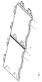
- FIG.1 . Fig.2 and Figure 3 a first embodiment of the plate according to the invention together with the plate-shaped carrier and FIGS. 4 . 5 . 6 and 7 modified formations of the plate-shaped carrier.
- Fig.1 is a plate, such as a granite slab for laying floors, designated 1.
- a plate-shaped carrier 2 On the underside of the plate 1, a plate-shaped carrier 2 is attached, which has locking members for the production of a snap connection with a further carrier 2.
- the further carrier 2 also carries a plate, which is not shown for clarity.
- the locking members are formed by projections 3, which are formed on elastically deflectable arms 4, and recesses 5.
- the arms 4 pivoted elastically inwardly be and engage the projections 3 in the corresponding recesses 5. In this case, the elastic arms 4 are deflected in the plane of the plate 1.
- the plates 1 can also be joined together in a direction perpendicular to the plane of the plate by inserting the projections 3 of one carrier 2 in the direction of the arrow 7 from above into the corresponding recesses 5 of the other carrier 2, without any deflection the arms 4 comes as is in Fig. 2 is shown.
- the carrier 2 is shown in the starting position with normal lines and in the assembled position with thin lines and denoted by 2 '.
- the elastically deflectable arms 4 project beyond the edge of the plate 1, the recesses 5 being formed in a rigid part of the plate-shaped carrier 2, namely in a region within the plate outline.
- the plate-shaped carrier 2 has a projecting over the edge of the plate 1 strip-like area 8, which extends at two adjacent edges 9 and 10 of the plate 1 and on which also the protruding arms 4 are formed.
- a joint seal can be arranged or molded by an injection molding process, as in Figure 3 is shown. In this case, two plates 1 are connected to each other and it can be seen that between the two plates 1 in the region 8, a gap is formed, which can be closed by a joint seal 17.
- the joint seal 17 can be used in this case when laying the plate in the appropriate joints.
- the joint seal is already factory-connected to the projecting portion 8 of the plate-shaped carrier 2 and / or with the edge 9 or 10 of the plate 1, wherein preferably the joint seal 17 is injection-molded or foamed by an injection molding process.
- arms 4 of the plate-shaped support 2 are arranged at an angle of 45 ° to the edge of the plate 1, so that a corresponding 45 ° -Fü deung according to the arrow 6 is favored.
- the arms 4 arranged in pairs, wherein the two arms 4 of a pair in mutually opposite directions directed projections 3 have. At two adjacent sides of the plate-shaped carrier 2 in each case two pairs of two arms 4 are arranged.
- the protruding arms 4 are arranged not only on two adjacent sides of the carrier 2 but on all sides, wherein corresponding recesses 5 are arranged on each side.
- the orientation of the plate 1 can be freely selected when joining with identically constructed plates.
- the resilient arms 11 of the plate-shaped carrier 2 are arranged in a region within the Plattenumrisses and there are the rigid locking members with the projections 12 on rigid parts 13 of the plate-shaped support 2 is formed.
- the projections 12 engage in corresponding recesses 14 of the elastically deflectable arms 11 a.
- the resilient arms are provided with projections or recesses.
- the projections are arranged on regions projecting beyond the plate edge or within the plate outline.
- both a male locking member 15 and a female locking member 16 are arranged, so that the orientation of the plate 1 can be freely selected when assembled with identically constructed plates. This is especially true of Advantage if certain structures or patterns applied to the plate surface are to be taken into consideration.
Landscapes
- Engineering & Computer Science (AREA)
- Architecture (AREA)
- Civil Engineering (AREA)
- Structural Engineering (AREA)
- General Engineering & Computer Science (AREA)
- Mechanical Engineering (AREA)
- Floor Finish (AREA)
- Finishing Walls (AREA)
Claims (16)
- Plaque destinée à être posée sur des sols, des murs, des plafonds, des façades ou similaires, à l'intérieur et à l'extérieur, avec des éléments de verrouillage qui coopèrent avec les éléments de verrouillage de plaques (1) voisines pour créer un assemblage emboîté entre celles-ci, lesquels éléments de verrouillage comprennent au moins une saillie (3, 12) ou un évidement (5, 14) et sont reliés à un support en forme de plaque (2) disposé sur la face inférieure de la plaque (1) ou formés sur celui-ci, caractérisée en ce que la saillie (3, 12) ou l'évidement (5, 14) est formé sur au moins un bras (4, 11) déformable de façon élastique dans le plan de la plaque (1), de sorte que l'assemblage emboîté peut être réalisé en déviant le bras et en emboîtant ensuite les éléments de verrouillage.
- Plaque selon la revendication 1, caractérisée en ce que le support (2) est formé sur la face inférieure de la plaque (1), formé par application de mousse ou formé par injection.
- Plaque selon la revendication 1 ou 2, caractérisée en ce que des bras (4, 11) déformables élastiquement sont formés en saillie au-delà du bord de la plaque (1).
- Plaque selon la revendication 1, 2 ou 3, caractérisée en ce que des bras (11) déformables élastiquement sont formés sous la plaque à l'intérieur du contour de la plaque, l'extrémité libre déformable élastiquement de chacun de ces bras (11) étant dirigée vers un bord de la plaque (1).
- Plaque selon l'une des revendications 1 à 4, caractérisée en ce que des bras déformables élastiquement (4, 11) sont disposés de façon à dépasser de seulement deux bords (9, 10) voisins l'un de l'autre de la plaque (1) ou dirigés vers ceux-ci.
- Plaque selon l'une des revendications 1 à 5, caractérisée en ce que la saillie (3, 12) ou l'évidement (5, 14) formé sur un bras déformable élastiquement (4, 11) coopère avec une saillie (3, 12) ou un évidement (5, 14) formé sur une partie rigide (13) d'une plaque (1) voisine.
- Plaque selon l'une des revendications 1 à 6, caractérisée en ce que la plaque (1) présente sur chacun de ses bords au moins un bras déformable élastiquement dépassant de ce bord (4) ou dirigé vers ce bord (11) et au moins un élément de verrouillage (13) rigide coopérant avec les bras déformables élastiquement (4, 11) d'une plaque (1) voisine.
- Plaque selon l'une des revendications 1 à 7, caractérisée en ce que les bras déformables élastiquement (4, 11) sont disposés par paires avec des saillies (3, 12) ou des évidements (5, 14) orientés dans des directions opposées les uns aux autres.
- Plaque selon l'une des revendications 1 à 8, caractérisée en ce que les bras déformables élastiquement (4, 11) forment avec un bord latéral de la plaque (1) un angle de 35° à 55°, de préférence de 45°.
- Plaque selon l'une des revendications 1 à 9, caractérisée en ce qu'une garniture d'étanchéité de joint (17) est reliée avec au moins deux bords (9, 10) voisins l'un de l'autre de la plaque (1) et/ou avec une zone (8) du support en forme de plaque (2) dépassant au-delà d'au moins deux bords (9, 10) voisins l'un de l'autre de la plaque (1), de préférence reliée par injection ou par application de mousse.
- Support en forme de plaque destiné à être appliqué sur la face inférieure d'une plaque (1) à poser sur des sols, des murs, des plafonds, des façades ou similaires à l'intérieur et à l'extérieur, avec lequel des éléments de verrouillage comprenant au moins une saillie (3, 12) ou un évidement (5, 14) sont reliés ou sur lequel de tels éléments de verrouillage sont formés, lesquels éléments de verrouillage coopèrent avec des éléments de verrouillage de supports (2) voisins pour créer des assemblages emboîtés, caractérisé en ce que la saillie (3, 12) ou l'évidement (5, 14) est formé sur au moins un bras (4, 11) déformable élastiquement dans le plan du support (2), de sorte que l'assemblage emboîté peut être réalisé en déviant le bras et en emboîtant ensuite les éléments de verrouillage, le bras déformable élastiquement (4, 11) formant avec un bord latéral du support (2) un angle de 35° à 55°, de préférence de 45°.
- Support en forme de plaque selon la revendication 11, caractérisé en ce que les bras déformables élastiquement (4, 11) sont disposés de façon à dépasser de seulement deux bords (9, 10) voisins l'un de l'autre du support en forme de plaque (2) ou à se diriger vers ceux-ci.
- Support en forme de plaque selon la revendication 11 ou 12, caractérisé en ce que la saillie (3, 12) ou l'évidement (5, 14) formé sur un bras déformable élastiquement (4, 11) coopère avec une saillie (3, 12) ou un évidement (5, 14) formé sur une partie rigide (13) d'un support (2) voisin.
- Support en forme de plaque selon la revendication 11, 12 ou 13, caractérisé en ce que le support (2) présente sur chacun de ses bords au moins un bras déformable élastiquement dépassant de ce bord (4) ou dirigé vers ce bord (11) et au moins un élément de verrouillage rigide (13) coopérant avec les bras déformables élastiquement (4, 11) d'un support (2) voisin.
- Support en forme de plaque selon l'une des revendications 11 à 14, caractérisé en ce que les bras déformables élastiquement (4, 11) sont disposés par paires avec des saillies (3, 12) ou des évidements (5, 14) orientés dans des directions opposées les uns aux autres.
- Support en forme de plaque selon l'une des revendications 11 à 15, caractérisée en ce qu'une garniture d'étanchéité de joint (17) est reliée à la zone (8) du support en forme de plaque (2) dépassant au-delà d'au moins deux bords (9, 10) voisins l'un de l'autre de la plaque, de préférence par injection ou par application de mousse.
Priority Applications (1)
| Application Number | Priority Date | Filing Date | Title |
|---|---|---|---|
| AT04737369T ATE424515T1 (de) | 2003-07-07 | 2004-07-05 | Platte zur verlegung auf böden, wänden, decken, fassaden oder dgl |
Applications Claiming Priority (2)
| Application Number | Priority Date | Filing Date | Title |
|---|---|---|---|
| AT4782003 | 2003-07-07 | ||
| PCT/AT2004/000239 WO2005003574A1 (fr) | 2003-07-07 | 2004-07-05 | Plaque destinee a etre appliquee sur des sols, ainsi que sur des murs, plafonds, façades ou analogues |
Publications (2)
| Publication Number | Publication Date |
|---|---|
| EP1642036A1 EP1642036A1 (fr) | 2006-04-05 |
| EP1642036B1 true EP1642036B1 (fr) | 2009-03-04 |
Family
ID=40427672
Family Applications (1)
| Application Number | Title | Priority Date | Filing Date |
|---|---|---|---|
| EP04737369A Expired - Lifetime EP1642036B1 (fr) | 2003-07-07 | 2004-07-05 | Plaque destinee a etre appliquee sur des sols, ainsi que sur des murs, plafonds, fa ades ou analogues |
Country Status (4)
| Country | Link |
|---|---|
| EP (1) | EP1642036B1 (fr) |
| AT (1) | ATE424515T1 (fr) |
| DE (1) | DE502004009090D1 (fr) |
| WO (1) | WO2005003574A1 (fr) |
Families Citing this family (17)
| Publication number | Priority date | Publication date | Assignee | Title |
|---|---|---|---|---|
| CN100425784C (zh) * | 2005-03-11 | 2008-10-15 | 罗生权 | 塑料龙骨实木地板 |
| EP1934417B1 (fr) | 2005-10-03 | 2012-05-23 | Tarkett SAS | Kit de construction de revêtement de surface |
| WO2007038989A1 (fr) * | 2005-10-05 | 2007-04-12 | Penrose Parkettgestaltung Gmbh | Surface de parquet, element de parquet et assemblage d'elements de parquet |
| GB0520309D0 (en) * | 2005-10-06 | 2005-11-16 | Specialised Panel Products Ltd | Improvements in and relating to flooring |
| ES2310100B1 (es) * | 2006-07-31 | 2009-11-10 | Insca Internacional, S.L. | Parquet. |
| DE102006027982B3 (de) * | 2006-06-14 | 2007-12-06 | Fritz Egger Gmbh & Co. | Bauteil, vorzugsweise für die Verkleidung von Fußböden, Wänden und Decken, sowie Verfahren zu dessen Herstellung |
| WO2008040039A1 (fr) * | 2006-10-03 | 2008-04-10 | Poschacher Natursteinwerke Gmbh & Co Kg | Plaques à poser au sol, au mur, au plafond, en façade ou similaire |
| EP2069587A1 (fr) * | 2006-10-05 | 2009-06-17 | Poschacher Natursteinwerke GmbH & Co Kg | Plaque à poser notamment au sol, au mur, au plafond, en façade ou similaire |
| ATE544920T1 (de) * | 2006-10-05 | 2012-02-15 | Poschacher Natursteinwerke Gmbh & Co Kg | Ein verfahren zum festlegen von platten an einem träger und eine platte mit einer einrichtung zum festlegen derselben an einem träger |
| CN101532331A (zh) | 2007-07-30 | 2009-09-16 | 诺瓦利斯股份有限公司 | 具有互锁设计的地板覆盖物 |
| MX2012007417A (es) * | 2009-12-23 | 2012-11-12 | Hong Kong Me Li Sheng Flooring Co Ltd | Una plancha de madera de piso facil de instalar. |
| WO2016001886A1 (fr) * | 2014-07-04 | 2016-01-07 | Dessington, Antony John Lee | Agencement de support pour un revêtement structural |
| GB201721514D0 (en) * | 2017-12-20 | 2018-01-31 | Winward Advantage Ltd | A set of parts and apparatus assembled therefrom |
| US20240360632A1 (en) * | 2021-08-31 | 2024-10-31 | Plastic Safety Systems, Inc. | Temporary walkway system with modular tiles interlocking in three-dimensions |
| PT117489B (pt) * | 2021-09-29 | 2023-07-04 | Issg Sports Innovations Lda | Sistema e método de encaixe para módulos de pavimento |
| WO2023200367A1 (fr) * | 2022-04-12 | 2023-10-19 | Денис САГИДУЛЛИН | Panneau décoratif réfléchissant la lumière |
| CN116607718A (zh) * | 2023-05-26 | 2023-08-18 | 常州市豪优杰智能科技有限公司 | 一种干法铺装瓷砖结构及铺装方法 |
Family Cites Families (8)
| Publication number | Priority date | Publication date | Assignee | Title |
|---|---|---|---|---|
| GB589635A (en) * | 1945-03-14 | 1947-06-25 | Laurence Victor Hughes | Improvements in or relating to floor-covering and the like material |
| US3657852A (en) * | 1969-09-15 | 1972-04-25 | Walter J Worthington | Floor tiles |
| DE29703123U1 (de) * | 1997-02-21 | 1997-06-05 | EMT Werkzeug- und Formenbau GmbH, 74523 Schwäbisch Hall | Bodenbelag |
| DE20107338U1 (de) * | 2001-04-28 | 2001-06-28 | Mateina, Ludger, 59227 Ahlen | Flexibles Bodenbelagsträgersystem |
| DE20114787U1 (de) * | 2001-09-06 | 2001-11-29 | debolon dessauer bodenbeläge GmbH & Co. KG, 06846 Dessau | Flächenförmiges Belagselement für belagsbedürftige Auslageflächen, das als Teilfläche ausgebildet montagefähig ist |
| DE10295140D2 (de) * | 2001-11-28 | 2004-12-23 | Mayer Hans | Verlegesystem für Bodenplatten |
| WO2003093605A1 (fr) * | 2002-05-03 | 2003-11-13 | Westminster Products Pty Ltd | Tuiles interconnectables et structures associees |
| DE10243196B4 (de) * | 2002-09-18 | 2007-03-22 | Kaindl Flooring Gmbh | Paneele mit Verbindungsklammer |
-
2004
- 2004-07-05 DE DE502004009090T patent/DE502004009090D1/de not_active Expired - Lifetime
- 2004-07-05 AT AT04737369T patent/ATE424515T1/de not_active IP Right Cessation
- 2004-07-05 WO PCT/AT2004/000239 patent/WO2005003574A1/fr not_active Ceased
- 2004-07-05 EP EP04737369A patent/EP1642036B1/fr not_active Expired - Lifetime
Also Published As
| Publication number | Publication date |
|---|---|
| DE502004009090D1 (de) | 2009-04-16 |
| EP1642036A1 (fr) | 2006-04-05 |
| ATE424515T1 (de) | 2009-03-15 |
| WO2005003574A1 (fr) | 2005-01-13 |
Similar Documents
| Publication | Publication Date | Title |
|---|---|---|
| EP1642036B1 (fr) | Plaque destinee a etre appliquee sur des sols, ainsi que sur des murs, plafonds, fa ades ou analogues | |
| DE10337352B3 (de) | Einrichtung zum Verbinden und Verriegeln von Bauplatten | |
| EP3321448B1 (fr) | Panneau | |
| EP1379739B1 (fr) | Ensemble consistant en des éléments de construction en forme de plaques et des éléments de connexion | |
| EP3298212A1 (fr) | Garniture de panneaux rectangulaires ou carrés joints les uns aux autres | |
| DE102005002297A1 (de) | Verbindung für plattenförmige Bauelemente, insbesondere für Fußbodenpaneele | |
| DE102007018309A1 (de) | Verbindung für plattenförmige Bauelemente | |
| WO2001002670A1 (fr) | Panneau et dispositif de fixation pour panneaux | |
| WO2001051732A1 (fr) | Panneau | |
| EP1490566A1 (fr) | Panneau et systeme de verrouillage pour panneaux | |
| WO2006032378A1 (fr) | Panneau, notamment panneau de plancher | |
| EP2845965B1 (fr) | Fixation d'un madrier sur une infrastructure | |
| WO2008040039A1 (fr) | Plaques à poser au sol, au mur, au plafond, en façade ou similaire | |
| AT413840B (de) | Platte zur verlegung auf böden, wänden, decken, fassaden oder dgl. | |
| DE102015102671B4 (de) | Paneele mit einer mechanischen Verbindung für diese Paneele, Verfahren zur Montage einer Verriegelungsfeder in einem Paneel und Verfahren zum Verbinden von Paneelen mit einer mechanischen Verbindung | |
| EP0149443B1 (fr) | Liaison de serrage entre panneaux doubles munis de traverses et un profilé, notamment pour des petites serres | |
| EP3372749B1 (fr) | Système de planches de sol | |
| DE19640128A1 (de) | Bodenbelag-Element | |
| EP1913215A1 (fr) | Revetement de sol | |
| EP3748103B1 (fr) | Revêtement de sol doté d'au moins un élément de raccordement | |
| AT9957U1 (de) | Platten zur verlegung auf böden, wänden, decken, fassaden oder dgl. | |
| EP2995746A2 (fr) | Liaison mecanique pour panneaux et procede de montage d'un ressort de verrouillage dans un panneau | |
| DE19823357A1 (de) | Fliese | |
| EP0151420A2 (fr) | Carreau | |
| DE29901547U1 (de) | Abdeckleiste für plattenförmige Bauelemente |
Legal Events
| Date | Code | Title | Description |
|---|---|---|---|
| PUAI | Public reference made under article 153(3) epc to a published international application that has entered the european phase |
Free format text: ORIGINAL CODE: 0009012 |
|
| 17P | Request for examination filed |
Effective date: 20060121 |
|
| AK | Designated contracting states |
Kind code of ref document: A1 Designated state(s): AT BE BG CH CY CZ DE DK EE ES FI FR GB GR HU IE IT LI LU MC NL PL PT RO SE SI SK TR |
|
| AX | Request for extension of the european patent |
Extension state: LT LV |
|
| RAX | Requested extension states of the european patent have changed |
Extension state: LT Payment date: 20060121 Extension state: LV Payment date: 20060121 |
|
| 17Q | First examination report despatched |
Effective date: 20080401 |
|
| GRAP | Despatch of communication of intention to grant a patent |
Free format text: ORIGINAL CODE: EPIDOSNIGR1 |
|
| GRAS | Grant fee paid |
Free format text: ORIGINAL CODE: EPIDOSNIGR3 |
|
| GRAA | (expected) grant |
Free format text: ORIGINAL CODE: 0009210 |
|
| AK | Designated contracting states |
Kind code of ref document: B1 Designated state(s): AT BE BG CH CY CZ DE DK EE ES FI FR GB GR HU IE IT LI LU MC NL PL PT RO SE SI SK TR |
|
| AX | Request for extension of the european patent |
Extension state: LT LV |
|
| REG | Reference to a national code |
Ref country code: GB Ref legal event code: FG4D Free format text: NOT ENGLISH |
|
| REG | Reference to a national code |
Ref country code: CH Ref legal event code: EP |
|
| REG | Reference to a national code |
Ref country code: IE Ref legal event code: FG4D Free format text: LANGUAGE OF EP DOCUMENT: GERMAN |
|
| REF | Corresponds to: |
Ref document number: 502004009090 Country of ref document: DE Date of ref document: 20090416 Kind code of ref document: P |
|
| PG25 | Lapsed in a contracting state [announced via postgrant information from national office to epo] |
Ref country code: FI Free format text: LAPSE BECAUSE OF FAILURE TO SUBMIT A TRANSLATION OF THE DESCRIPTION OR TO PAY THE FEE WITHIN THE PRESCRIBED TIME-LIMIT Effective date: 20090304 Ref country code: SI Free format text: LAPSE BECAUSE OF FAILURE TO SUBMIT A TRANSLATION OF THE DESCRIPTION OR TO PAY THE FEE WITHIN THE PRESCRIBED TIME-LIMIT Effective date: 20090304 Ref country code: NL Free format text: LAPSE BECAUSE OF FAILURE TO SUBMIT A TRANSLATION OF THE DESCRIPTION OR TO PAY THE FEE WITHIN THE PRESCRIBED TIME-LIMIT Effective date: 20090304 |
|
| NLV1 | Nl: lapsed or annulled due to failure to fulfill the requirements of art. 29p and 29m of the patents act | ||
| LTIE | Lt: invalidation of european patent or patent extension |
Effective date: 20090304 |
|
| PG25 | Lapsed in a contracting state [announced via postgrant information from national office to epo] |
Ref country code: SE Free format text: LAPSE BECAUSE OF FAILURE TO SUBMIT A TRANSLATION OF THE DESCRIPTION OR TO PAY THE FEE WITHIN THE PRESCRIBED TIME-LIMIT Effective date: 20090604 Ref country code: PL Free format text: LAPSE BECAUSE OF FAILURE TO SUBMIT A TRANSLATION OF THE DESCRIPTION OR TO PAY THE FEE WITHIN THE PRESCRIBED TIME-LIMIT Effective date: 20090304 |
|
| REG | Reference to a national code |
Ref country code: IE Ref legal event code: FD4D |
|
| PG25 | Lapsed in a contracting state [announced via postgrant information from national office to epo] |
Ref country code: IE Free format text: LAPSE BECAUSE OF FAILURE TO SUBMIT A TRANSLATION OF THE DESCRIPTION OR TO PAY THE FEE WITHIN THE PRESCRIBED TIME-LIMIT Effective date: 20090304 Ref country code: EE Free format text: LAPSE BECAUSE OF FAILURE TO SUBMIT A TRANSLATION OF THE DESCRIPTION OR TO PAY THE FEE WITHIN THE PRESCRIBED TIME-LIMIT Effective date: 20090304 Ref country code: CZ Free format text: LAPSE BECAUSE OF FAILURE TO SUBMIT A TRANSLATION OF THE DESCRIPTION OR TO PAY THE FEE WITHIN THE PRESCRIBED TIME-LIMIT Effective date: 20090304 Ref country code: PT Free format text: LAPSE BECAUSE OF FAILURE TO SUBMIT A TRANSLATION OF THE DESCRIPTION OR TO PAY THE FEE WITHIN THE PRESCRIBED TIME-LIMIT Effective date: 20090819 Ref country code: ES Free format text: LAPSE BECAUSE OF FAILURE TO SUBMIT A TRANSLATION OF THE DESCRIPTION OR TO PAY THE FEE WITHIN THE PRESCRIBED TIME-LIMIT Effective date: 20090615 |
|
| PG25 | Lapsed in a contracting state [announced via postgrant information from national office to epo] |
Ref country code: RO Free format text: LAPSE BECAUSE OF FAILURE TO SUBMIT A TRANSLATION OF THE DESCRIPTION OR TO PAY THE FEE WITHIN THE PRESCRIBED TIME-LIMIT Effective date: 20090304 Ref country code: SK Free format text: LAPSE BECAUSE OF FAILURE TO SUBMIT A TRANSLATION OF THE DESCRIPTION OR TO PAY THE FEE WITHIN THE PRESCRIBED TIME-LIMIT Effective date: 20090304 |
|
| REG | Reference to a national code |
Ref country code: HU Ref legal event code: AG4A Ref document number: E006099 Country of ref document: HU |
|
| PLBE | No opposition filed within time limit |
Free format text: ORIGINAL CODE: 0009261 |
|
| STAA | Information on the status of an ep patent application or granted ep patent |
Free format text: STATUS: NO OPPOSITION FILED WITHIN TIME LIMIT |
|
| PG25 | Lapsed in a contracting state [announced via postgrant information from national office to epo] |
Ref country code: DK Free format text: LAPSE BECAUSE OF FAILURE TO SUBMIT A TRANSLATION OF THE DESCRIPTION OR TO PAY THE FEE WITHIN THE PRESCRIBED TIME-LIMIT Effective date: 20090304 Ref country code: BG Free format text: LAPSE BECAUSE OF FAILURE TO SUBMIT A TRANSLATION OF THE DESCRIPTION OR TO PAY THE FEE WITHIN THE PRESCRIBED TIME-LIMIT Effective date: 20090604 |
|
| BERE | Be: lapsed |
Owner name: POSCHACHER NATURSTEINWERKE GMBH & CO KG Effective date: 20090731 |
|
| 26N | No opposition filed |
Effective date: 20091207 |
|
| PG25 | Lapsed in a contracting state [announced via postgrant information from national office to epo] |
Ref country code: MC Free format text: LAPSE BECAUSE OF NON-PAYMENT OF DUE FEES Effective date: 20090731 |
|
| REG | Reference to a national code |
Ref country code: CH Ref legal event code: PL |
|
| GBPC | Gb: european patent ceased through non-payment of renewal fee |
Effective date: 20090705 |
|
| PG25 | Lapsed in a contracting state [announced via postgrant information from national office to epo] |
Ref country code: CH Free format text: LAPSE BECAUSE OF NON-PAYMENT OF DUE FEES Effective date: 20090731 Ref country code: LI Free format text: LAPSE BECAUSE OF NON-PAYMENT OF DUE FEES Effective date: 20090731 |
|
| PG25 | Lapsed in a contracting state [announced via postgrant information from national office to epo] |
Ref country code: GB Free format text: LAPSE BECAUSE OF NON-PAYMENT OF DUE FEES Effective date: 20090705 |
|
| PG25 | Lapsed in a contracting state [announced via postgrant information from national office to epo] |
Ref country code: BE Free format text: LAPSE BECAUSE OF NON-PAYMENT OF DUE FEES Effective date: 20090731 |
|
| PG25 | Lapsed in a contracting state [announced via postgrant information from national office to epo] |
Ref country code: GR Free format text: LAPSE BECAUSE OF FAILURE TO SUBMIT A TRANSLATION OF THE DESCRIPTION OR TO PAY THE FEE WITHIN THE PRESCRIBED TIME-LIMIT Effective date: 20090605 |
|
| PG25 | Lapsed in a contracting state [announced via postgrant information from national office to epo] |
Ref country code: AT Free format text: LAPSE BECAUSE OF NON-PAYMENT OF DUE FEES Effective date: 20090705 |
|
| PG25 | Lapsed in a contracting state [announced via postgrant information from national office to epo] |
Ref country code: IT Free format text: LAPSE BECAUSE OF FAILURE TO SUBMIT A TRANSLATION OF THE DESCRIPTION OR TO PAY THE FEE WITHIN THE PRESCRIBED TIME-LIMIT Effective date: 20090304 |
|
| PG25 | Lapsed in a contracting state [announced via postgrant information from national office to epo] |
Ref country code: LU Free format text: LAPSE BECAUSE OF NON-PAYMENT OF DUE FEES Effective date: 20090705 |
|
| PG25 | Lapsed in a contracting state [announced via postgrant information from national office to epo] |
Ref country code: TR Free format text: LAPSE BECAUSE OF FAILURE TO SUBMIT A TRANSLATION OF THE DESCRIPTION OR TO PAY THE FEE WITHIN THE PRESCRIBED TIME-LIMIT Effective date: 20090304 |
|
| PG25 | Lapsed in a contracting state [announced via postgrant information from national office to epo] |
Ref country code: CY Free format text: LAPSE BECAUSE OF FAILURE TO SUBMIT A TRANSLATION OF THE DESCRIPTION OR TO PAY THE FEE WITHIN THE PRESCRIBED TIME-LIMIT Effective date: 20090304 |
|
| PGFP | Annual fee paid to national office [announced via postgrant information from national office to epo] |
Ref country code: HU Payment date: 20110712 Year of fee payment: 8 |
|
| PGFP | Annual fee paid to national office [announced via postgrant information from national office to epo] |
Ref country code: FR Payment date: 20120711 Year of fee payment: 9 Ref country code: DE Payment date: 20120629 Year of fee payment: 9 |
|
| PG25 | Lapsed in a contracting state [announced via postgrant information from national office to epo] |
Ref country code: HU Free format text: LAPSE BECAUSE OF NON-PAYMENT OF DUE FEES Effective date: 20120706 |
|
| REG | Reference to a national code |
Ref country code: FR Ref legal event code: ST Effective date: 20140331 |
|
| PG25 | Lapsed in a contracting state [announced via postgrant information from national office to epo] |
Ref country code: DE Free format text: LAPSE BECAUSE OF NON-PAYMENT OF DUE FEES Effective date: 20140201 |
|
| REG | Reference to a national code |
Ref country code: DE Ref legal event code: R119 Ref document number: 502004009090 Country of ref document: DE Effective date: 20140201 |
|
| PG25 | Lapsed in a contracting state [announced via postgrant information from national office to epo] |
Ref country code: FR Free format text: LAPSE BECAUSE OF NON-PAYMENT OF DUE FEES Effective date: 20130731 |