EP1642059B1 - Element d'etancheite servant de raccord et pourvu de dents de type cliquet - Google Patents
Element d'etancheite servant de raccord et pourvu de dents de type cliquet Download PDFInfo
- Publication number
- EP1642059B1 EP1642059B1 EP04740585A EP04740585A EP1642059B1 EP 1642059 B1 EP1642059 B1 EP 1642059B1 EP 04740585 A EP04740585 A EP 04740585A EP 04740585 A EP04740585 A EP 04740585A EP 1642059 B1 EP1642059 B1 EP 1642059B1
- Authority
- EP
- European Patent Office
- Prior art keywords
- connector device
- connector
- elastomer insert
- transverse opening
- sealing
- Prior art date
- Legal status (The legal status is an assumption and is not a legal conclusion. Google has not performed a legal analysis and makes no representation as to the accuracy of the status listed.)
- Expired - Lifetime
Links
- 229920001971 elastomer Polymers 0.000 claims abstract description 59
- 239000000806 elastomer Substances 0.000 claims abstract description 57
- 238000007789 sealing Methods 0.000 claims abstract description 53
- 239000000463 material Substances 0.000 claims abstract description 21
- 238000003780 insertion Methods 0.000 claims description 19
- 230000037431 insertion Effects 0.000 claims description 19
- 239000003566 sealing material Substances 0.000 claims description 10
- 239000003795 chemical substances by application Substances 0.000 claims description 6
- 230000002787 reinforcement Effects 0.000 claims description 6
- 239000000853 adhesive Substances 0.000 claims description 5
- 230000001070 adhesive effect Effects 0.000 claims description 5
- 239000000969 carrier Substances 0.000 claims description 5
- 238000009434 installation Methods 0.000 claims description 5
- 239000000314 lubricant Substances 0.000 claims description 4
- 238000005260 corrosion Methods 0.000 claims description 3
- 238000004519 manufacturing process Methods 0.000 claims description 3
- XLYOFNOQVPJJNP-UHFFFAOYSA-N water Substances O XLYOFNOQVPJJNP-UHFFFAOYSA-N 0.000 claims description 3
- 238000006073 displacement reaction Methods 0.000 claims description 2
- 238000011161 development Methods 0.000 description 8
- 230000018109 developmental process Effects 0.000 description 8
- 239000011248 coating agent Substances 0.000 description 6
- 238000000576 coating method Methods 0.000 description 6
- 230000000694 effects Effects 0.000 description 5
- 230000007704 transition Effects 0.000 description 4
- 239000004604 Blowing Agent Substances 0.000 description 3
- 239000004743 Polypropylene Substances 0.000 description 2
- 230000006978 adaptation Effects 0.000 description 2
- 230000007797 corrosion Effects 0.000 description 2
- 235000019589 hardness Nutrition 0.000 description 2
- 239000004033 plastic Substances 0.000 description 2
- 229920001155 polypropylene Polymers 0.000 description 2
- 239000003380 propellant Substances 0.000 description 2
- 239000000565 sealant Substances 0.000 description 2
- 230000008961 swelling Effects 0.000 description 2
- 230000004913 activation Effects 0.000 description 1
- 230000004323 axial length Effects 0.000 description 1
- 230000005540 biological transmission Effects 0.000 description 1
- 230000015572 biosynthetic process Effects 0.000 description 1
- 238000006243 chemical reaction Methods 0.000 description 1
- 239000002131 composite material Substances 0.000 description 1
- 238000010276 construction Methods 0.000 description 1
- 238000012937 correction Methods 0.000 description 1
- 238000013461 design Methods 0.000 description 1
- 230000007613 environmental effect Effects 0.000 description 1
- 238000011156 evaluation Methods 0.000 description 1
- 238000005187 foaming Methods 0.000 description 1
- 238000005755 formation reaction Methods 0.000 description 1
- 238000010438 heat treatment Methods 0.000 description 1
- 238000007373 indentation Methods 0.000 description 1
- 230000001788 irregular Effects 0.000 description 1
- 238000005259 measurement Methods 0.000 description 1
- 239000000203 mixture Substances 0.000 description 1
- 238000012986 modification Methods 0.000 description 1
- 230000004048 modification Effects 0.000 description 1
- -1 polypropylene Polymers 0.000 description 1
- 229910052572 stoneware Inorganic materials 0.000 description 1
Images



Classifications
-
- F—MECHANICAL ENGINEERING; LIGHTING; HEATING; WEAPONS; BLASTING
- F16—ENGINEERING ELEMENTS AND UNITS; GENERAL MEASURES FOR PRODUCING AND MAINTAINING EFFECTIVE FUNCTIONING OF MACHINES OR INSTALLATIONS; THERMAL INSULATION IN GENERAL
- F16L—PIPES; JOINTS OR FITTINGS FOR PIPES; SUPPORTS FOR PIPES, CABLES OR PROTECTIVE TUBING; MEANS FOR THERMAL INSULATION IN GENERAL
- F16L41/00—Branching pipes; Joining pipes to walls
- F16L41/08—Joining pipes to walls or pipes, the joined pipe axis being perpendicular to the plane of a wall or to the axis of another pipe
- F16L41/088—Joining pipes to walls or pipes, the joined pipe axis being perpendicular to the plane of a wall or to the axis of another pipe fixed using an elastic grommet between the extremity of the tube and the wall
Definitions
- the invention relates to a connecting device for a secondary pipe in combination with a transverse opening, as it is found with the perforated wall of a main pipe, a shaft or the like and whose diameter can vary considerably, according to the preamble of claim 1.
- connection seal of this kind is from the EP 0 795 712 B1 known.
- the sealing effect of this connection device is excellent.
- a hollow plug elastomeric insert is provided for the transverse opening which engages a relatively soft tubular sealing wall portion in the transverse opening to seal the tube wall transverse opening upon contact due to the harder connection port.
- the elastomeric insert has a support collar which forms a stop on the main pipeline around the transverse opening and whose material is preferably set softer than that of the tubular sealing wall region.
- the connecting piece is made of a harder material than that of the elastomeric insert in order to press it sufficiently firmly against the pipe wall of the transverse opening during assembly of the connecting device.
- the elastomeric insert has an area with a tapered inner surface occupied by locking ring zones.
- the spigot has a tapered portion of the outer surface, which is also occupied by locking ring zones.
- These locking ring zones each have inclined surfaces which are inclined in the insertion direction of the parts, so that when the inclined surfaces of the connecting piece strike the inclined surface of the elastomer insert during assembly, these inclined surfaces can slide against each other, wherein there is a ratcheting engagement of the locking ring zones, when the Anschlußstutzen.in the opening of the elastomeric insert is pushed.
- the locking ring zones are provided with lubricant, which can be applied both at the factory and on the construction site.
- the contact pressure of the elastomer insert is gradually increased until the reaction force becomes so high that further telescoping of the parts is practically no longer possible, so to speak a stop for the connecting piece is formed.
- the basic shape surfaces of the elastomer insert and the connecting piece are arranged substantially concentrically with one another when the connecting device is assembled.
- guide surfaces may be provided on the inner circumference of the opening of the elastomer insert in the region of the support collar and on the outer circumference of the connection piece in the region of the transition between the engagement end and the socket end.
- axial guide means in the form of axial grooves in the elastomer insert and in the form of axially extending ribs may be provided on the connecting piece. These guide means serve to avoid any skewing during assembly of the connecting piece with the elastomer insert.
- a second hollow plug-shaped, in part relatively soft and provided with locking ring zones elastomer insert for installation in the transverse opening from the interior of the main pipe and a hollow An horrkonus with locking ring zones corresponding to that of the connecting piece is provided.
- This special embodiment is particularly suitable for liners in which the coating inside the tube is broken through by the subsequently produced transverse opening and the transition between concrete core and inliner coating can not be well sealed afterwards.
- the second elastomeric insert To the second elastomeric insert press into the pipe wall in the region of the transverse opening, the hollow An horrkonus is provided which preferably has a Abstützflansch which applies to the support collar of the second elastomeric insert.
- the transverse opening may be protected by an applied coating, however, the critical transition zone for inliner coating by the second elastomeric insert is protected to be reached by the aggressive medium.
- a pipe extension on the connecting piece which sealingly bears against a ring seal in the region of the second elastomer insert or the hollow pressure cone.
- the connecting device according to the invention has at least one strand with swellable sealing material.
- a strand can then improve the sealing effect by swelling.
- the sealing material of the strand can swell in particular under the action of water.
- a self-sealing effect can be achieved when moisture from the pipes or from the environment enters the pipes inside.
- the strand with swellable sealing material is arranged according to a development of this embodiment in an annular groove of a Sperringzone.
- Such a strand may be present both in the locking ring zone of the hollow-plug-shaped elastomer insert and in the locking zone of the connecting piece.
- a further advantageous possibility of achieving a subsequent and / or additional sealing is to provide at least one sealing element which can be activated by the action of heat for the connecting device.
- a simple and effective sealing can be achieved according to a development of this embodiment in a simple manner by an activatable sealing element containing a material which increases its volume by the action of heat. Due to the increase in volume existing column can be filled directly by the material of the sealing element or other parts of the connecting device, in particular wall portions of the connecting piece and the elastomer insert are pressed against each other. The required heat for the activation can be generated in a simple manner by means of an electrical resistance heater according to another embodiment of this embodiment.
- At least one pressure sensor is provided for determining the contact pressure of one of the parts of the connection device. With the pressure sensor can be checked whether a desired or required for the tightness of the connection pressure of the parts is reached, so as to be able to detect, for example, any leaks already during assembly of the device or before commissioning.
- a plurality of pressure sensors arranged uniformly spaced in the circumferential direction of one of the parts of the connecting device can be provided for determining the contact pressure. From any existing differences in the pressure readings can then be determined whether the parts of the connection device were joined sufficiently uniformly sealing.
- the at least one pressure sensor can be arranged on or in the elastomer insert.
- one or more sensors may also be present on or in the connecting piece.
- the pressure sensor (s) can also be arranged on or in this annular seal in order to be able to check a correct seating of this seal and / or the parts of the connecting device sealed with this seal.
- At least one transponder and / or a data carrier is provided for the acquisition, storage or transmission of measured values of one of the parts of the connection device.
- the transponder and / or data carrier can be checked whether a desired or necessary for the function of the connection device reading of the parts is achieved, so as to be able to detect, for example, any leaks already during assembly of the connection device or before commissioning.
- a plurality of transponders arranged equidistantly in the circumferential direction of one of the parts of the connecting device and / or a data carrier for determining the measured values may also be provided become. From any existing differences in the measured values can then be determined whether the parts were joined together sufficiently uniformly sealing.
- the at least one transponder and / or a data carrier can be arranged on or in the elastomer insert.
- one or more transponders and / or data carriers can also be present on or in the connecting piece.
- an arrangement on or within the An horrkonus according to the above-described development with a second elastomeric insert, or on or in this second elastomeric insert possible. If the connecting device has an annular seal, the transponder and / or data carrier can also be arranged on or in this seal in order to be able to check a correct seating of this seal and / or the parts of the connecting device sealed with this seal.
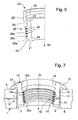
- Fig. 1 taken which shows a hollow plug elastomeric insert 10 in a subsequent transverse opening 2 of a main pipe 1.
- These may be stoneware pipes or concrete pipes.
- reinforcements 8 are provided, which are shown here as longitudinal reinforcement and transverse reinforcement are.
- this reinforcement 8 can be cut through, which is one of the reasons why the transverse opening 2 generally can not be made very accurately, which means that both the single diameter can be irregular and the diameter of the case may be different in case. The same difficulties are encountered in the walls of manholes.
- the hollow plug elastomer insert 10 has a sealing wall portion 11 and a flange or support collar 12.
- the sealing wall portion 11 has an outer surface 13 and a tapered inner surface 14.
- the outer surface 13 is largely matched to the diameter of the transverse opening 2, i. is cylindrical or slightly conical and has an axial length corresponding to the length of the transverse opening 2, but at least a length for covering the trimmed reinforcements 8.
- On the inside of the elastomer insert 10 is located in addition to the tapered inner surface 14 nor a centering section 15.
- the tapered inner surface 14 is provided with locking ring zones 16, which are seen in cross-section sawtooth, ie each having a more inclined surface 16a (in the drawing above) and a lighter inclined surface 16b. In addition to the annular teeth thus annular tooth spaces 16 c are formed.
- the outer surface 13 of the elastomeric insert 10 may be provided with barb-like profilings 19 which, viewed in the insertion direction IN of the elastomer insert 10, rest against the transverse opening 2 and block the removal of the elastomer insert 10.
- the support collar 12 has generally a bell shape or a saddle shape to support the outer circumference 3 of the pipe 1.
- the saddle shape results from the pipe bend of the main pipe 1.
- For flexible support of the support collar 12 at the edge of the transverse opening 2 indentations 17 are provided so that the bell-shaped support collar 12 can assume saddle shape.
- the elastomeric insert 10 may be constructed of different hardnesses of its material.
- the sealing wall region 11 consists of a softer material as the locking ring zones 16 and possibly also the support collar 12.
- the relatively softer elastomer region 11 so adapts better to the irregularities and variations in the diameter of the transverse opening 2 in order to seal them.
- the slightly greater hardness of the locking ring zones 16 is selected because of sliding against each other on further locking ring zones 26.
- a slightly harder support collar has an increased spring force, so that it rests firmly on the edge of the transverse opening 2. It is possible for the ring zones 16 and the support collar 12 to combine harder and further qualities (components) of the material.
- Fig. 2 shows the connecting piece 20, which is selected from a relatively harder material compared to the elastomeric insert 10, even against its harder component, and may for example consist of polypropylene (PP) or PVC.
- the connecting piece 20 has a hollow engaging end 21 and a hollow sleeve end 22.
- the engagement end 21 comprises a tapered outer surface 23 and a likewise tapering inner surface 24.
- the outer surface 23 is occupied by locking ring zones 26 which form a toothing with sawtooth cross-section.
- the front in the direction of insertion IN inclined surfaces 26a of the locking ring zones 26 are, as seen from the wall of the connecting piece 20, against the insertion direction IN inclined.
- the rear surfaces 26b in the direction of insertion can, for example, also be inclined from the wall of the connecting piece 20, counter to the direction of insertion IN, in order to achieve good toothing. However, the surfaces 26b may also be perpendicular to the insertion direction IN, or slightly inclined in the direction of insertion. Between the locking ring zones 26 are annular spaces 26c.
- the sleeve end 22 of the connecting piece 20 has a cylindrical inner side 27 with a groove 28 for receiving a ring seal, not shown, to which the secondary pipe, also not shown, sealingly applies.
- the sleeve end 22 may be provided with formations that serve as mounting means when engaging a mounting tool.
- the transverse opening 2 for the installation of the elastomeric insert 10 is prepared. This is done by order one It is also possible to apply the agent (adhesive corrosion protection) by means of the elastomeric insert 10, wherein the agent is suitably applied to the outer surface 13 of the elastomer insert 10 or the elastomeric insert 10 with Such an order, which is protected by a cover during storage and transport, is delivered.
- the agent also serves as a lubricant when installing the elastomeric insert 10.
- a true lubricant can be used, as is known.
- the fitting of the connecting piece 20 in the cavity of the elastomeric insert 10 is strictly in the axial direction of the transverse opening 2. For this purpose come after reaching a certain insertion amount, the centering surfaces 15 and 25 to the effect and align the connecting piece 20 in order to achieve a precise concentric position of the parts to each other.
- axial grooves can be mounted in the elastomer insert 10, which divide the annular zones 16 into individual ring zone segments, and at the appropriate location of the connecting piece 20 may be provided axially extending ribs, which in the axial Engage grooves of the elastomeric insert 10, whereby the connecting piece 20 during installation strictly axial and concentric to be led.
- the expression "locking ring zone” or “ring groove” in the claims should therefore also include non-closed (ie interrupted) geometric shapes of these embodiments.
- the outer surface 13 of the elastomeric insert 10 coated with an adhesive and can be delivered protected by a cover it is also possible to brush at least one of the areas occupied with locking ring zones 16, 26 surfaces 14 or 23 with adhesive and protected by a cover to deliver.
- cavities are provided in the elastomeric insert 10 which are filled with post-sealant and open at higher pressure to release the post-sealant and thereby cause a re-seal. Such cavities may be provided near the inner end of the seal wall portion 11.
- Fig. 4 shows a connecting device with a second elastomeric insert 30 and a hollow An horrkonus 40.
- the second elastomeric insert 30 corresponds to the first elastomeric insert 10 with the difference that the support collar 32 of the second insert 30 is relatively small and is adapted to the inner contour 4 of the pipe 1, in Difference to the adaptation to the outer contour 3 in the first use 10.
- the second elastomeric insert 30 is used especially when the pipeline 1 has an inliner coating 5. If in such a pipe subsequently a transverse opening 2 is drilled and the bore reveal is subsequently provided with a layer 6, there is a critical point 7 at the transition of layers 5 and 6, could attack in the aggressive media, because this point 7 breaks because of different Thermal expansions of core concrete to inliner coating slightly on.
- the invention remedy the fact that the second elastomeric insert 30 covers this critical point 7.
- the pressure cone 40 is provided for firmly pressing the second insert 30 and is therefore drawn into the transverse opening 2 during assembly of the connection device.
- the pressure cone 40 on a Abstützflansch 42, on which a hook-like tool can attack. Otherwise, the pressure cone 40 is simulated to the connecting piece 20 with respect to the locking ring zones 26, which engage in corresponding locking ring zones of the second elastomeric insert 30.
- hook-like tool for pressing the Anyakkonus 40 can hook-shaped grippers can be used, which are pushed through the transverse opening 2 in the pipe interior 4.
- Such a tool may be similar to an umbrella without stringing trained, that is, you can fold the hooks on the tool shank, if you push the hooks through the transverse opening 2 into the pipe interior 4, and you can extend the hooks there to the Abstönflansch 42nd Attack and press the Anyakkonus to the second insert 30.
- Fig. 5 shows a modification of the connecting device with the second elastomeric insert 30.
- a modified connecting piece 50 is applied, which has a pipe extension 51, and on the second elastomeric insert 30, a ring seal 52 is provided, which cooperates with the tube extension 51, so that the wall of the transverse opening. 2 is not reached by medium flowing through the pipe 1 and the connecting device.
- the seal 52 could also be mounted in the interior of the pressure cone 40. Furthermore, it is possible to frictionally connect the tube extension 51 to the pressure cone 40, for which purpose a separate connection piece may also be useful. With the invention, a gas-tight connection of a secondary pipe to a main line can be achieved.
- FIG. 6 is a further education of in Fig. 2 shown connecting piece 20 for a connecting device according to the invention.
- the in Fig. 6 shown connecting piece 20 has a plurality of strands 43 with swellable sealing material. It is particularly advantageous if the sealing material of the strands 43 swells under the action of water.
- the strands 43 are arranged with swellable sealing material between the surfaces 26a, 26b in the annular grooves 26c of the locking ring zone 26 respectively.
- FIG. 7 Another possibility to provide a connecting device with such strands 43, is in Fig. 7 shown.
- the strands 43 of in Fig. 7 Elastomeric insert 10 shown are also arranged in the annular grooves 16c of the locking ring 16 of the elastomer insert 10.
- the arrangement of such sealing strands in the area of the Sperringzone, as in Fig. 6 or Fig. 7 is shown is advantageous, since it is precisely in this area by the insertion of the connecting piece 20 and the resulting expansion and contact pressure of the elastomeric insert 10, a seal is to be achieved, which is further improved by a Nachabdichtung means of the swellable strands 43.
- Fig. 8 shows a further education in Fig. 3 shown connection device.
- composite connection device additionally has a activatable by heat sealing element 44.
- the sealing element 44 is formed in this embodiment as a circumferential strand, which is arranged in the region of the engagement end 21 of the connecting piece 20. At the in Fig. 8 illustrated embodiment, the sealing element 44 extends specifically in the interior of the engagement end 21 below the Sperringzone 26.
- the sealing member 44 includes a material 45, which increases its volume by the action of heat.
- Particularly suitable for this purpose is a blowing agent-containing rubber or plastic material or suitable blowing agent-containing rubber and / or plastic mixtures.
- Such a material may advantageously also be vulcanizable under the action of heat, also in conjunction with the blowing agent.
- the increase in volume of the material 45 can advantageously take place, for example, by foaming of the material due to a propellant released from the propellant when heated.
- the material 45 may be additionally surrounded by an elastic or stretchable sheath for
- the sealing element 44 also has an electrical resistance heater 46 in the form of a running inside the material 45 heating wire, which with in FIG. 8 not shown external terminals is connected, to which after assembly of the connection device from the outside, a power source can be connected.
- the material 45 then swells during operation of the resistance heater 46 and thus also deforms the adjacent wall region of the locking ring zone 26, which in particular bulges outward by the swelling material 45 and presses sealingly against the locking ring zone 16 of the elastomeric insert 10.
- a sealing element in the elastomer insert 10 for example, be provided in the interior of the elastomer insert 10 under the sealing wall portion 11.
- sealing elements 44 may be provided in the elastomer insert 10 and / or the connecting piece 20. Also, alternatively or additionally, by suitable arrangement of one or more sealing elements, other outer surfaces of the elastomer inserts 10, or the connecting piece 20 can be subsequently sealed. For example, one or more sealing elements 44 may be arranged in the centering section 15 or below the centering surface 25.
- Connection device shown also has one or more pressure sensors 49 for determining the contact pressure of the respective parts with the sensors 49.
- sensors 49 There are various possibilities for the arrangement of the sensors 49.
- a sensor 49, as in FIG Fig. 8 is shown to be disposed inside the elastomeric insert 10.
- four such sensors 49 are preferably arranged uniformly distributed in the interior of the elastomer insert 10 along a circle extending in the circumferential direction of the sealing wall region 11.
- the sealing wall region 11 is compressed in the radial direction, so that a pressure is exerted on the sensors 49 and a corresponding measuring signal can be read out. If the measured values of the individual sensors 49 differ greatly, this indicates a leak, or at least a bad seal, and corrective measures, such as a correction of the position of the connecting piece 20, can be made. For example, deviations of the minimum and maximum measured values obtained from at least 20% to 50% or more may indicate that the contact pressure along the circumference is too uneven and leakage is likely. Furthermore, at a detected insufficient uniformity of the contact pressure and an activatable sealing element 44 are activated to obtain an improved seal.
- a further exemplary possibility of the arrangement for such pressure sensors 49 is shown.
- Fig. 10 shows a part of a further education in Fig. 5 shown embodiment of a connecting device according to the invention.
- the detail shown shows the region of the connecting device with the annular seal 52, which cooperates with the tube extension 51 of the modified connecting piece 50.
- the ring seal 52 has a plurality of pressure sensors 49, which in turn advantageously can be arranged at uniform intervals along the circumferential direction of the seal 52.
- four such sensors 49 are used, of which, due to the sectional view in FIG Fig. 10 only two sensors 49 can be seen.
- the pressure sensors 49 are disposed inside the seal 52. According to a variant of this embodiment, the sensors 49 are mounted on the outside of the seal 52. Even with a ring seal 52 with sensors 49, an evaluation of the measured values obtained by the sensors 49 can give indications as to whether the seal 52 is seated correctly and is sealed.
- pressure sensors 49 are merely exemplary and the pressure sensors 49 may also be arranged elsewhere in the connection device. Generally, an arrangement of the sensors 49 is advantageous where a sealing effect is to be achieved by the pressing together of surfaces of different parts.
- the connecting device shown has one or more transponders and / or data carriers 59 for detecting, storing or transmitting measured values of the respective parts.
- a transponder and / or data carrier 59 as in Fig. 8 is shown to be disposed inside the elastomeric insert 10.
- an activatable sealing element 44 can be activated in order to obtain an improved seal.
- Fig. 8 a further exemplary possibility of the arrangement for such transponder and / or data carrier 59 is shown.
- the transponders and / or data carriers 59 are located inside the connecting piece 20.
- connection device It is advantageously possible to check via pressure sensors (49), transponders and / or data carriers (59) as to whether a measurement value of the parts (10, 20, 30, 40, 50) of the connection device required for the function can be achieved. This takes place already during assembly of the connection device, but also during assembly, commissioning or during operation of the connection device.
- Fig. 9 shows on the basis of a section of the connecting device, a different type of arrangement of a sealing element 44.
- the activatable sealing element 44 extends not in the interior, but in a groove of an outer surface of one of the parts of the connecting device.
- the outer surface with the sealing elements 44 is the locking ring zone 16 of the elastomer part 10, or the locking ring zone 26 of the connecting piece 20, wherein the sealing elements 44 (similar to those in FIG 6 and 7 shown strands 43 with swellable sealing material) in each case in the annular grooves 16c and 26c are arranged.
Landscapes
- Engineering & Computer Science (AREA)
- General Engineering & Computer Science (AREA)
- Mechanical Engineering (AREA)
- Gasket Seals (AREA)
- Coupling Device And Connection With Printed Circuit (AREA)
- Connector Housings Or Holding Contact Members (AREA)
- Details Of Connecting Devices For Male And Female Coupling (AREA)
- Non-Disconnectible Joints And Screw-Threaded Joints (AREA)
- Sealing Devices (AREA)
- Joints With Pressure Members (AREA)
- Branch Pipes, Bends, And The Like (AREA)
- Joints With Sleeves (AREA)
Claims (28)
- Dispositif de raccord pour une conduite tubulaire auxiliaire en combinaison avec une ouverture transversale (2), telle qu'elle se présente dans la paroi percée d'une conduite tubulaire principale (1), d'une gaine ou similaire, et dont le diamètre peut varier considérablement, ayant les caractéristiques suivantes :a) un insert en élastomère (10) en forme de bouchon creux, en partie relativement mou, présente un bord de support flexible (12) et une région de paroi d'étanchéité (11) avec une surface intérieure (14) se rétrécissant et avec une surface extérieure (13) qui est généralement adaptée à l'ouverture transversale (2) ;b) une tubulure de raccordement (20) relativement plus dure présente une extrémité d'engagement (21) avec une surface extérieure (23) se rétrécissant pour coopérer avec la surface intérieure (14) de l'insert en élastomère (10) et une extrémité de manchon (22) pour coopérer avec la conduite tubulaire auxiliaire ;c) le rétrécissement de la surface intérieure (14) de l'insert en élastomère (10) et le rétrécissement de la surface extérieure (23) de la tubulure de raccordement (20) ont lieu dans la direction d'insertion (IN) des pièces (10, 20) dans laquelle celles-ci sont enfoncées l'une dans l'autre ou dans l'ouverture transversale (2) ;d) la région de paroi d'étanchéité (11) avec la surface intérieure (14) se rétrécissant est pourvue de zones de bagues de blocage (16) qui sont inclinées dans la direction d'insertion (IN) et vers l'intérieur de l'espace creux de l'insert élastomère, ete) la surface extérieure (23) se rétrécissant de l'extrémité d'engagement (21) est également pourvue de zones de bagues de blocage (26), qui, vues depuis l'extrémité d'engagement (21), sont inclinées vers l'extérieur à l'encontre de la direction d'insertion (IN) ;f) et par un déplacement supplémentaire de la tubulure de raccordement (20) dans la direction d'insertion (IN), l'insert élastomère (10) est étiré progressivement et est pressé plus fortement contre l'ouverture transversale (2), caractérisé en ce queg) lors de l'insertion de l'insert élastomère (10) dans l'ouverture transversale (2) et de l'assemblage subséquent de la tubulure de raccordement (20) à l'insert élastomère (10), les zones de bagues de blocage (16, 26) viennent en prise les unes dans les autres à la manière de cliquets et s'encliquètent dans des rainures annulaires (16c, 26c),h) en ce que les zones de bagues de blocage (16, 26) forment une denture de section transversale en forme de dents de scie.
- Dispositif de raccord selon la revendication 1, caractérisé en ce que les zones de bagues de blocage (16, 26), par comparaison avec la caractéristique de la région de paroi d'étanchéité (11), se composent de matériaux relativement plus durs.
- Dispositif de raccord selon la revendication 1 ou 2, caractérisé en ce que les zones de bagues de blocage (16, 26) sont pourvues d'un moyen glissant.
- Dispositif de raccord selon l'une quelconque des revendications 1 à 3, caractérisé en ce que le rétrécissement de la surface interne (14) de l'insert élastomère est choisi de manière à être suffisamment important pour former une butée ou un arrêt de montage pour la tubulure de raccordement (20).
- Dispositif de raccord selon l'une quelconque des revendications 1 à 4, caractérisé en ce que les surfaces de la forme de base de l'insert élastomère (10) et de la tubulure de raccordement (20) dans le cas du dispositif de raccord à monter et monté, sont disposées essentiellement concentriquement les unes aux autres, les surfaces de guidage (15) réalisées sur l'insert élastomère coopérant avec des surfaces de guidage (25) réalisées sur la tubulure de raccordement.
- Dispositif de raccord selon l'une quelconque des revendications 1 à 5, caractérisé en ce que la surface extérieure (13) de l'insert élastomère (10) est cylindrique ou se rétrécit légèrement dans la direction d'insertion (IN) et est pourvue de profilages (19) en forme de barbes, qui s'appliquent lors du montage dans la direction d'insertion contre l'ouverture transversale (2) et qui réalisent un blocage à l'encontre de la direction d'insertion.
- Dispositif de raccord selon l'une quelconque des revendications 1 à 6, caractérisé en ce que la région de paroi d'étanchéité (11) de l'insert élastomère (10) est réalisée sous forme de pièce tubulaire de longueur suffisante, pour éventuellement recouvrir de manière hermétique des renforcements (8) entamés lors de la fabrication de l'ouverture transversale (2).
- Dispositif de raccord selon la revendication 7, caractérisé en ce que la surface extérieure (13) de l'insert élastomère (10) est revêtue d'un agent de protection contre la corrosion et/ou d'un agent adhésif, qui est protégé par une feuille de recouvrement pendant le stockage et le transport, jusqu'avant l'installation.
- Dispositif de raccord selon l'une quelconque des revendications 1 à 8, caractérisé en ce que la région de paroi d'étanchéité (11) de l'insert élastomère (10) présente un ou plusieurs espaces creux remplis d'agent d'étanchéité, qui s'ouvrent sous l'effet de la pression après que la tubulure de raccordement (20) a été montée, et déchargent l'agent d'étanchéité, qui provoque une étanchéité à réactivation.
- Dispositif de raccord selon l'une quelconque des revendications 1 à 9, caractérisé en ce que le bord de support (12) de l'insert élastomère (10) est réalisé avec une plus grande dureté par rapport à la région de paroi d'étanchéité (11).
- Dispositif de raccord selon l'une quelconque des revendications 1 à 10, caractérisé en ce que le bord de support (12) de l'insert élastomère (10) est adapté au diamètre de la conduite tubulaire principale (1), pour l'ouverture transversale (2) de laquelle est prévu le bord de support (12).
- Dispositif de raccord selon l'une quelconque des revendications 1 à 11, caractérisé en ce que l'on prévoit un deuxième insert élastomère (30) en forme de bouchon creux, en partie relativement mou, pour l'insertion dans l'ouverture transversale (2) depuis l'intérieur (4) de la conduite tubulaire principale (1), et un cône de pression creux (40) avec des zones de bagues de blocage correspondant à celui de la tubulure de raccordement (20).
- Dispositif de raccord selon la revendication 12, caractérisé en ce que l'extrémité d'engagement du cône de pression creux (40) présente une bride de support (42) qui est adaptée au bord de support (32) du deuxième insert élastomère (30).
- Dispositif de raccord selon la revendication 12 ou 13, caractérisé en ce que la tubulure de raccordement (50) présente une saillie tubulaire (51) qui s'applique de manière hermétique contre un joint d'étanchéité annulaire (52) sur le deuxième insert élastomère ou sur le cône de pression creux.
- Dispositif de raccord selon la revendication 12 ou 13, caractérisé en ce que la tubulure de raccordement (50) présente une saillie tubulaire (51) et/ou une pièce de connexion séparée, afin d'être connectée par engagement par force au cône de pression (40).
- Dispositif de raccord selon l'une quelconque des revendications précédentes, caractérisé par au moins un boudin (43) en matériau d'étanchéité gonflant.
- Dispositif de raccord selon la revendication 16, caractérisé en ce que le matériau d'étanchéité du boudin (43) gonfle en contact avec de l'eau.
- Dispositif de raccord selon la revendication 16 ou 17, caractérisé en ce que l'au moins un boudin (43) en matériau d'étanchéité gonflant est disposé dans une rainure annulaire (16c, 26c) d'une zone de bague de blocage (16, 26).
- Dispositif de raccord selon l'une quelconque des revendications précédentes, caractérisé par au moins un élément d'étanchéité (44) pouvant être activé sous l'effet de la chaleur.
- Dispositif de raccord selon l'une quelconque des revendications précédentes, caractérisé en ce que l'élément d'étanchéité (44) contient un matériau (45) dont le volume augmente sous l'effet de la chaleur.
- Dispositif de raccord selon la revendication 19 ou 20, caractérisé en ce que l'élément d'étanchéité (44) présente un chauffage par résistance électrique (46).
- Dispositif de raccord selon l'une quelconque des revendications précédentes, caractérisé par au moins un capteur de pression (49) pour déterminer la pression d'application de l'une des pièces (10, 20, 30, 40, 50) du dispositif de raccord.
- Dispositif de raccord selon la revendication 22, caractérisé par plusieurs capteurs de pression (49) répartis uniformément dans la direction périphérique de l'une des pièces (10, 20, 30, 40, 50) du dispositif de raccord pour détecter la pression d'application.
- Dispositif de raccord selon la revendication 22 ou 23, caractérisé en ce qu'au moins un capteur de pression (49) est disposé sur ou dans l'une des pièces comprenant l'insert élastomère (10, 30), la tubulure de raccordement (20), ou le cône de pression (40) du dispositif de raccord.
- Dispositif de raccord selon la revendication 22 ou 23, caractérisé en ce qu'au moins un capteur de pression (49) est disposé sur ou dans un joint d'étanchéité annulaire (52).
- Dispositif de raccord selon l'une quelconque des revendications précédentes, caractérisé par au moins un transpondeur et/ou un support de données (59) pour détecter, stocker ou transférer des valeurs de mesure de l'une des pièces (10, 20, 30, 40, 50) du dispositif de raccord.
- Dispositif de raccord selon la revendication 26, caractérisé en ce qu'au moins un transpondeur et/ou un support de données (59) est disposé sur ou dans l'une des parties comprenant l'insert élastomère (10, 30), la tubulure de raccordement (20), ou le cône de pression (40) du dispositif de raccord.
- Dispositif de raccord selon l'une quelconque des revendications précédentes, caractérisé en ce que l'on peut vérifier par le biais de capteurs de pression (49), de transpondeurs et/ou de supports de données (59), si une valeur de mesure des pièces (10, 20, 30, 40, 50) du dispositif de raccord, requise pour le fonctionnement, peut être obtenue.
Priority Applications (1)
| Application Number | Priority Date | Filing Date | Title |
|---|---|---|---|
| PL04740585T PL1642059T3 (pl) | 2003-07-04 | 2004-07-02 | Uszczelka przyłącza z zębami zapadkowymi |
Applications Claiming Priority (2)
| Application Number | Priority Date | Filing Date | Title |
|---|---|---|---|
| DE20310390U DE20310390U1 (de) | 2003-07-04 | 2003-07-04 | Anschlussdichtung mit Ratschenzähnen |
| PCT/EP2004/007231 WO2005003615A1 (fr) | 2003-07-04 | 2004-07-02 | Element d'etancheite servant de raccord et pourvu de dents de type cliquet |
Publications (2)
| Publication Number | Publication Date |
|---|---|
| EP1642059A1 EP1642059A1 (fr) | 2006-04-05 |
| EP1642059B1 true EP1642059B1 (fr) | 2010-08-18 |
Family
ID=33441924
Family Applications (1)
| Application Number | Title | Priority Date | Filing Date |
|---|---|---|---|
| EP04740585A Expired - Lifetime EP1642059B1 (fr) | 2003-07-04 | 2004-07-02 | Element d'etancheite servant de raccord et pourvu de dents de type cliquet |
Country Status (7)
| Country | Link |
|---|---|
| US (1) | US7918486B2 (fr) |
| EP (1) | EP1642059B1 (fr) |
| AT (1) | ATE478300T1 (fr) |
| CA (1) | CA2565741C (fr) |
| DE (2) | DE20310390U1 (fr) |
| PL (1) | PL1642059T3 (fr) |
| WO (1) | WO2005003615A1 (fr) |
Families Citing this family (33)
| Publication number | Priority date | Publication date | Assignee | Title |
|---|---|---|---|---|
| ATE514028T1 (de) * | 2005-07-13 | 2011-07-15 | Beele Eng Bv | System zur versiegelung eines raums zwischen der innenwand einer röhrenförmigen öffnung und mindestens einer mindestens teilweise in der öffnung endenden röhre oder leitung |
| ES2394649T3 (es) | 2006-03-20 | 2013-02-04 | Beele Engineering B.V. | Sistema para sellar dinámicamente un manguito de canalización a través del cual se extiende un tubo o cable |
| DE202008005803U1 (de) * | 2008-04-25 | 2009-09-03 | Rehau Ag + Co. | Rohrmuffe und Kugelgelenk-Kupplung zur Verbindung von Rohren |
| DE102008021470A1 (de) * | 2008-04-29 | 2009-11-19 | Pt-Poly-Tec Gmbh Vertrieb Und Herstellung Von Dichtungssystemen | Elastomereinsatz für einen Nebenrohranschluss |
| WO2009140966A1 (fr) * | 2008-05-22 | 2009-11-26 | Mogens Vilhelmsen | Élément d'étanchéité, revêtement glissant et système comprenant un tel élément d'étanchéité et un tel revêtement glissant |
| GB0902506D0 (en) * | 2009-02-14 | 2009-04-01 | Swellfix Bv | Connector seal |
| AT509196B1 (de) * | 2010-03-12 | 2011-07-15 | Henn Gmbh & Co Kg | Verfahren zum verbinden eines endabschnitts einer leitung für flüssige oder gasförmige medien mit einem steckverbinder |
| AT509195B1 (de) * | 2010-03-12 | 2011-07-15 | Henn Gmbh & Co Kg | Verfahren zum verbinden eines endabschnitts einer leitung für flüssige oder gasförmige medien mit einem steckverbinder |
| ES2392791T3 (es) * | 2010-05-25 | 2012-12-13 | Beele Engineering B.V. | Un conjunto y un procedimiento para proporcionar un sistema de sellado en una abertura |
| US20120020740A1 (en) * | 2010-07-21 | 2012-01-26 | Norio Otsuga | Connection structure for a manhole pipe and a sewer main pipe |
| JP5829857B2 (ja) * | 2010-10-20 | 2015-12-09 | 株式会社山田製作所 | ステアリング装置における操作レバー |
| ES2626753T3 (es) | 2012-08-30 | 2017-07-25 | Beele Engineering B.V. | Sistema de estanqueidad para un espacio anular |
| US9130362B2 (en) * | 2012-12-20 | 2015-09-08 | Remy Technologies, L.L.C. | Connector member including a locking element |
| NL2010304C2 (en) | 2013-02-14 | 2014-08-18 | Beele Eng Bv | System for sealingly holding cables which extend through an opening. |
| US9261129B2 (en) * | 2013-07-08 | 2016-02-16 | Lockon Llc | Through-hull fitting |
| US9989252B2 (en) * | 2013-08-22 | 2018-06-05 | Noritz Corporation | Exhaust adapter, exhaust structure for water heater, and method for installing exhaust adapter |
| JP6134285B2 (ja) * | 2014-03-27 | 2017-05-24 | 株式会社コガネイ | マニホールド電磁弁 |
| ES2686201T3 (es) * | 2014-04-24 | 2018-10-16 | Henn Gmbh & Co Kg. | Subgrupo de enchufe |
| US9528643B2 (en) | 2014-12-02 | 2016-12-27 | Cnh Industrial Canada, Ltd. | Air grommet connector |
| EP3150891A1 (fr) * | 2015-09-29 | 2017-04-05 | HILTI Aktiengesellschaft | Passage de conduite destine a passer des conduites a travers un composant |
| US10760721B1 (en) * | 2016-10-18 | 2020-09-01 | Hydro-Gear Limited Partnership | Swivel fitting adaptor and assembly |
| US10823317B1 (en) | 2016-10-18 | 2020-11-03 | Hydro-Gear Limited Partnership | Swivel fitting adaptor and assembly |
| US10557573B2 (en) * | 2016-11-04 | 2020-02-11 | United Technologies Corporation | Feed through seals and fittings |
| US10221978B2 (en) * | 2016-12-21 | 2019-03-05 | Fca Us Llc | Automobile air hose assembly with a one-way quick snap coupling |
| JP6577977B2 (ja) | 2017-06-14 | 2019-09-18 | 矢崎総業株式会社 | パッキン |
| DE102017122786A1 (de) * | 2017-09-29 | 2019-04-04 | IT-InnoTec GmbH | Anschlussvorrichtung für eine Nebenrohrleitung |
| US10722324B2 (en) * | 2018-01-08 | 2020-07-28 | Stoma Ventures, LLC | Adapter for a tailpiece for a dental valve |
| US20190219207A1 (en) | 2018-01-16 | 2019-07-18 | Rain Bird Corporation | Push To Connect Coupling |
| DE102018109685A1 (de) * | 2018-04-23 | 2019-10-24 | IT-InnoTec GmbH | Anschlussvorrichtung |
| CN110748534A (zh) * | 2019-11-19 | 2020-02-04 | 徐州领航液压油路块制造有限公司 | 一种液压油路块对接结构 |
| US11204114B2 (en) | 2019-11-22 | 2021-12-21 | Trinity Bay Equipment Holdings, LLC | Reusable pipe fitting systems and methods |
| US11324659B1 (en) * | 2020-10-21 | 2022-05-10 | Balboa Water Group, Llc | Bathing installation fitting and grommet assembly |
| IL280146B2 (en) * | 2021-01-13 | 2024-01-01 | Rivulis Plastro Ltd | Drip irrigation lateral connector to feeder pipe |
Family Cites Families (29)
| Publication number | Priority date | Publication date | Assignee | Title |
|---|---|---|---|---|
| US806156A (en) * | 1905-03-28 | 1905-12-05 | Dale Marshall | Lock for nuts and bolts and the like. |
| US1471045A (en) * | 1922-12-20 | 1923-10-16 | Maupin Dexter Woodson | Pipe coupler |
| FR1011831A (fr) * | 1949-12-27 | 1952-06-27 | Cie De Pont A Mousson | Joint perfectionné pour tuyaux |
| US2825584A (en) * | 1955-11-18 | 1958-03-04 | Exxon Research Engineering Co | Threaded pipe coupling with bushing |
| US3749424A (en) * | 1972-06-05 | 1973-07-31 | Kdi American Products Inc | Water conduit connector |
| US4005884A (en) * | 1972-06-21 | 1977-02-01 | Mordechai Drori | Pipe coupling |
| DE3246768C1 (de) * | 1982-12-17 | 1989-01-12 | Daimler-Benz Ag, 7000 Stuttgart | Gas- und fluessigkeitsdichte Verbindung zwischen einem Kunststoffkoerper und einem darin durch Umfliessen mit einer plastifizierten Kunststoffmasse unter Druck eingebett eten Metallkoerper |
| US4607865A (en) * | 1984-10-16 | 1986-08-26 | Vetco Offshore Industries, Inc. | Connector, ratcheting type |
| GB8618235D0 (en) * | 1986-07-25 | 1986-09-03 | Lucas Ind Plc | Pressure cylinder pipe coupling |
| US4802792A (en) * | 1986-10-17 | 1989-02-07 | Mpc Industries, Inc. | Bushings for joining rigid objects to flexible membranes |
| US4694513A (en) * | 1987-01-22 | 1987-09-22 | Kiziah Floyd G | Drain |
| US4828296A (en) * | 1987-02-09 | 1989-05-09 | Swagelok Quick-Connect Co. | Bulkhead mounting for fluid fittings |
| US4768560A (en) * | 1987-05-08 | 1988-09-06 | Logsdon Duane D | Pipe plugs |
| US4817991A (en) | 1987-06-19 | 1989-04-04 | Arneson Products, Inc. | Safety fitting for a vacuum orifice in a swimming pool |
| US4989902A (en) * | 1988-05-05 | 1991-02-05 | Norman A. Nelson | Ratcheting and threaded well connector |
| US4900066A (en) * | 1988-11-01 | 1990-02-13 | Vetco Gray Inc. | Pipe connector |
| SE464569B (sv) * | 1990-01-26 | 1991-05-13 | Volvo Ab | Anordning vid braensletankar |
| DE9308441U1 (de) | 1993-06-05 | 1993-08-05 | PT-POLY-TEC GmbH Vertrieb und Herstellung von Dichtsystemen, 63150 Heusenstamm | Anschlußdichtung an einem Betonrohr |
| US5433487A (en) * | 1994-05-23 | 1995-07-18 | Kuhn; Mark A. | Wall penetration sleeve |
| SE515100C2 (sv) * | 1994-06-08 | 2001-06-11 | Forsheda Ab | Anordning för avtätning av en spalt |
| US5456499A (en) * | 1994-08-16 | 1995-10-10 | Conbraco Industries, Inc. | Hull fitting |
| DE29604662U1 (de) | 1996-03-13 | 1997-07-17 | PT - POLY - TEC GmbH Vertrieb und Herstellung von Dichtungssystemen, 63150 Heusenstamm | Anschlußvorrichtung |
| WO1997036128A1 (fr) * | 1996-03-25 | 1997-10-02 | Kunststoffröhren Sendenhorst Gmbh | Raccord pour canalisations en beton |
| US5971444A (en) * | 1996-06-24 | 1999-10-26 | World Fitting, L.L.C. | Through wall connector |
| US5954345A (en) * | 1996-10-10 | 1999-09-21 | Chrysler Corporation | Grommet for transmission oil fill tube |
| NZ505216A (en) * | 1997-11-18 | 2003-05-30 | Oystertec Plc | Method of interconecting an end of a pipe with a hollow structure having a screw threaded tubular inlet to form a joint , with first and second seals , the second seal between tubular inlet and pipe end , pipe end distorted outward |
| JP3889924B2 (ja) * | 2000-11-17 | 2007-03-07 | 本田技研工業株式会社 | ブローバイガス還元装置用流量制御弁の取付構造 |
| SE519409C2 (sv) * | 2000-12-21 | 2003-02-25 | Faluplast Ab | Röranslutningsdon |
| US6557825B2 (en) * | 2001-03-30 | 2003-05-06 | Cherne Industries Incorporated | Air admittance valve connector assembly |
-
2003
- 2003-07-04 DE DE20310390U patent/DE20310390U1/de not_active Expired - Lifetime
-
2004
- 2004-07-02 US US10/563,249 patent/US7918486B2/en not_active Expired - Fee Related
- 2004-07-02 EP EP04740585A patent/EP1642059B1/fr not_active Expired - Lifetime
- 2004-07-02 AT AT04740585T patent/ATE478300T1/de active
- 2004-07-02 DE DE502004011558T patent/DE502004011558D1/de not_active Expired - Lifetime
- 2004-07-02 PL PL04740585T patent/PL1642059T3/pl unknown
- 2004-07-02 WO PCT/EP2004/007231 patent/WO2005003615A1/fr not_active Ceased
- 2004-07-02 CA CA2565741A patent/CA2565741C/fr not_active Expired - Fee Related
Also Published As
| Publication number | Publication date |
|---|---|
| DE502004011558D1 (de) | 2010-09-30 |
| US20070108763A1 (en) | 2007-05-17 |
| ATE478300T1 (de) | 2010-09-15 |
| CA2565741C (fr) | 2012-02-28 |
| WO2005003615A1 (fr) | 2005-01-13 |
| DE20310390U1 (de) | 2004-11-11 |
| US7918486B2 (en) | 2011-04-05 |
| CA2565741A1 (fr) | 2005-01-13 |
| EP1642059A1 (fr) | 2006-04-05 |
| PL1642059T3 (pl) | 2011-02-28 |
Similar Documents
| Publication | Publication Date | Title |
|---|---|---|
| EP1642059A1 (fr) | Element d'etancheite servant de raccord et pourvu de dents de type cliquet | |
| DE69701379T2 (de) | Rohrverbindung | |
| AT401417B (de) | Schiebehülsen-verbindung für kunststoffrohre | |
| DE102007008066B4 (de) | Fitting | |
| DE19651817C2 (de) | Rohrpreßkupplung | |
| EP2410222A1 (fr) | Dispositif de fixation et d'étanchéification d'une conduite passant à travers une ouverture de mur de bâtiment | |
| DE2517826A1 (de) | Vorrichtung zur dichten durchfuehrung von kabeln durch eine wandung insbesondere fuer anschlussdosen | |
| DE19817136A1 (de) | Leitungssystem | |
| DE102013224027B4 (de) | Durchführungsvorrichtung für Leitungen, insbesondere Hauseinführung | |
| DE10215608B4 (de) | Rohrverbinder | |
| DE102020119002B3 (de) | Rohrmuffe | |
| EP2457011B1 (fr) | Procédé pour relier une pièce de raccordement avec un conduit thermo-isolé | |
| DE10146674B4 (de) | Anschlussdichtung | |
| EP2985504B1 (fr) | Raccord avec douille de sertissage | |
| DE4401672C2 (de) | Rohrverbinder | |
| DE4134049A1 (de) | Dichtelement fuer muffenrohre | |
| EP0080110A2 (fr) | Dispositif pour fixer un tuyau souple à un élément de raccord | |
| DE102010031656A1 (de) | Vorrichtung zum Einbau eines Messfühlers | |
| DE2650371B2 (de) | Kupplungsmuffe aus Kunststoff für eine zugfeste Rohrverbindung | |
| DE202020106135U1 (de) | Dübel und Befestigungssystem | |
| DE3632463C2 (fr) | ||
| EP3982026B1 (fr) | Procédé de renforcement de la force de pression d'un joint d'étanchéité et systéme de tuyaux comprenant un renforceur de force de pression | |
| DE102020110420A1 (de) | Prüfbare Leitungsdurchführung | |
| DE4243625C2 (de) | Anschlußstutzen | |
| DE3413632C2 (fr) |
Legal Events
| Date | Code | Title | Description |
|---|---|---|---|
| PUAI | Public reference made under article 153(3) epc to a published international application that has entered the european phase |
Free format text: ORIGINAL CODE: 0009012 |
|
| 17P | Request for examination filed |
Effective date: 20060117 |
|
| AK | Designated contracting states |
Kind code of ref document: A1 Designated state(s): AT BE BG CH CY CZ DE DK EE ES FI FR GB GR HU IE IT LI LU MC NL PL PT RO SE SI SK TR |
|
| DAX | Request for extension of the european patent (deleted) | ||
| RAP1 | Party data changed (applicant data changed or rights of an application transferred) |
Owner name: REHAU AG + CO |
|
| GRAP | Despatch of communication of intention to grant a patent |
Free format text: ORIGINAL CODE: EPIDOSNIGR1 |
|
| GRAS | Grant fee paid |
Free format text: ORIGINAL CODE: EPIDOSNIGR3 |
|
| GRAA | (expected) grant |
Free format text: ORIGINAL CODE: 0009210 |
|
| AK | Designated contracting states |
Kind code of ref document: B1 Designated state(s): AT BE BG CH CY CZ DE DK EE ES FI FR GB GR HU IE IT LI LU MC NL PL PT RO SE SI SK TR |
|
| REG | Reference to a national code |
Ref country code: GB Ref legal event code: FG4D Free format text: NOT ENGLISH |
|
| REG | Reference to a national code |
Ref country code: CH Ref legal event code: EP |
|
| REG | Reference to a national code |
Ref country code: IE Ref legal event code: FG4D Free format text: LANGUAGE OF EP DOCUMENT: GERMAN |
|
| REF | Corresponds to: |
Ref document number: 502004011558 Country of ref document: DE Date of ref document: 20100930 Kind code of ref document: P |
|
| REG | Reference to a national code |
Ref country code: RO Ref legal event code: EPE |
|
| REG | Reference to a national code |
Ref country code: SE Ref legal event code: TRGR |
|
| RAP2 | Party data changed (patent owner data changed or rights of a patent transferred) |
Owner name: REHAU AG + CO Owner name: PT-POLY-TEC GMBH VERTRIEB UND HERSTELLUNG VON DICH |
|
| REG | Reference to a national code |
Ref country code: NL Ref legal event code: VDEP Effective date: 20100818 |
|
| REG | Reference to a national code |
Ref country code: SK Ref legal event code: T3 Ref document number: E 8211 Country of ref document: SK |
|
| PG25 | Lapsed in a contracting state [announced via postgrant information from national office to epo] |
Ref country code: BG Free format text: LAPSE BECAUSE OF FAILURE TO SUBMIT A TRANSLATION OF THE DESCRIPTION OR TO PAY THE FEE WITHIN THE PRESCRIBED TIME-LIMIT Effective date: 20101118 Ref country code: SI Free format text: LAPSE BECAUSE OF FAILURE TO SUBMIT A TRANSLATION OF THE DESCRIPTION OR TO PAY THE FEE WITHIN THE PRESCRIBED TIME-LIMIT Effective date: 20100818 Ref country code: PT Free format text: LAPSE BECAUSE OF FAILURE TO SUBMIT A TRANSLATION OF THE DESCRIPTION OR TO PAY THE FEE WITHIN THE PRESCRIBED TIME-LIMIT Effective date: 20101220 Ref country code: CY Free format text: LAPSE BECAUSE OF FAILURE TO SUBMIT A TRANSLATION OF THE DESCRIPTION OR TO PAY THE FEE WITHIN THE PRESCRIBED TIME-LIMIT Effective date: 20100818 |
|
| REG | Reference to a national code |
Ref country code: PL Ref legal event code: T3 |
|
| REG | Reference to a national code |
Ref country code: IE Ref legal event code: FD4D |
|
| REG | Reference to a national code |
Ref country code: HU Ref legal event code: AG4A Ref document number: E009169 Country of ref document: HU |
|
| PG25 | Lapsed in a contracting state [announced via postgrant information from national office to epo] |
Ref country code: NL Free format text: LAPSE BECAUSE OF FAILURE TO SUBMIT A TRANSLATION OF THE DESCRIPTION OR TO PAY THE FEE WITHIN THE PRESCRIBED TIME-LIMIT Effective date: 20100818 Ref country code: GR Free format text: LAPSE BECAUSE OF FAILURE TO SUBMIT A TRANSLATION OF THE DESCRIPTION OR TO PAY THE FEE WITHIN THE PRESCRIBED TIME-LIMIT Effective date: 20101119 |
|
| PG25 | Lapsed in a contracting state [announced via postgrant information from national office to epo] |
Ref country code: DK Free format text: LAPSE BECAUSE OF FAILURE TO SUBMIT A TRANSLATION OF THE DESCRIPTION OR TO PAY THE FEE WITHIN THE PRESCRIBED TIME-LIMIT Effective date: 20100818 Ref country code: IE Free format text: LAPSE BECAUSE OF FAILURE TO SUBMIT A TRANSLATION OF THE DESCRIPTION OR TO PAY THE FEE WITHIN THE PRESCRIBED TIME-LIMIT Effective date: 20100818 |
|
| PG25 | Lapsed in a contracting state [announced via postgrant information from national office to epo] |
Ref country code: EE Free format text: LAPSE BECAUSE OF FAILURE TO SUBMIT A TRANSLATION OF THE DESCRIPTION OR TO PAY THE FEE WITHIN THE PRESCRIBED TIME-LIMIT Effective date: 20100818 |
|
| PLBE | No opposition filed within time limit |
Free format text: ORIGINAL CODE: 0009261 |
|
| STAA | Information on the status of an ep patent application or granted ep patent |
Free format text: STATUS: NO OPPOSITION FILED WITHIN TIME LIMIT |
|
| PG25 | Lapsed in a contracting state [announced via postgrant information from national office to epo] |
Ref country code: ES Free format text: LAPSE BECAUSE OF FAILURE TO SUBMIT A TRANSLATION OF THE DESCRIPTION OR TO PAY THE FEE WITHIN THE PRESCRIBED TIME-LIMIT Effective date: 20101129 |
|
| 26N | No opposition filed |
Effective date: 20110519 |
|
| PGFP | Annual fee paid to national office [announced via postgrant information from national office to epo] |
Ref country code: SK Payment date: 20110608 Year of fee payment: 8 |
|
| REG | Reference to a national code |
Ref country code: DE Ref legal event code: R097 Ref document number: 502004011558 Country of ref document: DE Effective date: 20110519 |
|
| PGFP | Annual fee paid to national office [announced via postgrant information from national office to epo] |
Ref country code: IT Payment date: 20110622 Year of fee payment: 8 |
|
| PGFP | Annual fee paid to national office [announced via postgrant information from national office to epo] |
Ref country code: CH Payment date: 20110822 Year of fee payment: 8 |
|
| PGFP | Annual fee paid to national office [announced via postgrant information from national office to epo] |
Ref country code: GB Payment date: 20110830 Year of fee payment: 8 Ref country code: HU Payment date: 20110616 Year of fee payment: 8 Ref country code: RO Payment date: 20110627 Year of fee payment: 8 |
|
| PG25 | Lapsed in a contracting state [announced via postgrant information from national office to epo] |
Ref country code: MC Free format text: LAPSE BECAUSE OF NON-PAYMENT OF DUE FEES Effective date: 20110731 |
|
| PGFP | Annual fee paid to national office [announced via postgrant information from national office to epo] |
Ref country code: CZ Payment date: 20120615 Year of fee payment: 9 |
|
| PGFP | Annual fee paid to national office [announced via postgrant information from national office to epo] |
Ref country code: LU Payment date: 20120713 Year of fee payment: 9 Ref country code: PL Payment date: 20120614 Year of fee payment: 9 |
|
| PGFP | Annual fee paid to national office [announced via postgrant information from national office to epo] |
Ref country code: BE Payment date: 20120711 Year of fee payment: 9 |
|
| GBPC | Gb: european patent ceased through non-payment of renewal fee |
Effective date: 20120702 |
|
| REG | Reference to a national code |
Ref country code: SK Ref legal event code: MM4A Ref document number: E 8211 Country of ref document: SK Effective date: 20120702 |
|
| REG | Reference to a national code |
Ref country code: DE Ref legal event code: R081 Ref document number: 502004011558 Country of ref document: DE Owner name: REHAU AG + CO., DE Free format text: FORMER OWNER: REHAU AG + CO., 95111 REHAU, DE Effective date: 20130215 Ref country code: DE Ref legal event code: R081 Ref document number: 502004011558 Country of ref document: DE Owner name: PT-POLY-TEC GMBH VERTRIEB UND HERSTELLUNG VON , DE Free format text: FORMER OWNER: REHAU AG + CO., 95111 REHAU, DE Effective date: 20130215 Ref country code: DE Ref legal event code: R081 Ref document number: 502004011558 Country of ref document: DE Owner name: REHAU AG + CO, DE Free format text: FORMER OWNER: REHAU AG + CO, 95111 REHAU, DE Effective date: 20130215 Ref country code: DE Ref legal event code: R081 Ref document number: 502004011558 Country of ref document: DE Owner name: PT-POLY-TEC GMBH VERTRIEB UND HERSTELLUNG VON , DE Free format text: FORMER OWNER: REHAU AG + CO, 95111 REHAU, DE Effective date: 20130215 |
|
| PG25 | Lapsed in a contracting state [announced via postgrant information from national office to epo] |
Ref country code: HU Free format text: LAPSE BECAUSE OF NON-PAYMENT OF DUE FEES Effective date: 20120703 Ref country code: GB Free format text: LAPSE BECAUSE OF NON-PAYMENT OF DUE FEES Effective date: 20120702 Ref country code: RO Free format text: LAPSE BECAUSE OF NON-PAYMENT OF DUE FEES Effective date: 20120702 |
|
| PG25 | Lapsed in a contracting state [announced via postgrant information from national office to epo] |
Ref country code: SK Free format text: LAPSE BECAUSE OF NON-PAYMENT OF DUE FEES Effective date: 20120702 Ref country code: IT Free format text: LAPSE BECAUSE OF NON-PAYMENT OF DUE FEES Effective date: 20120702 |
|
| PG25 | Lapsed in a contracting state [announced via postgrant information from national office to epo] |
Ref country code: TR Free format text: LAPSE BECAUSE OF FAILURE TO SUBMIT A TRANSLATION OF THE DESCRIPTION OR TO PAY THE FEE WITHIN THE PRESCRIBED TIME-LIMIT Effective date: 20100818 |
|
| PGFP | Annual fee paid to national office [announced via postgrant information from national office to epo] |
Ref country code: FI Payment date: 20130815 Year of fee payment: 10 |
|
| REG | Reference to a national code |
Ref country code: AT Ref legal event code: PC Ref document number: 478300 Country of ref document: AT Kind code of ref document: T Owner name: PT-POLY-TEC-GMBH VERTRIEB UND HERSTELLUNG VON , DE Effective date: 20131119 |
|
| BERE | Be: lapsed |
Owner name: REHAU A.G. + CO Effective date: 20130731 |
|
| PG25 | Lapsed in a contracting state [announced via postgrant information from national office to epo] |
Ref country code: CZ Free format text: LAPSE BECAUSE OF NON-PAYMENT OF DUE FEES Effective date: 20130702 |
|
| REG | Reference to a national code |
Ref country code: CH Ref legal event code: PL |
|
| PG25 | Lapsed in a contracting state [announced via postgrant information from national office to epo] |
Ref country code: LI Free format text: LAPSE BECAUSE OF NON-PAYMENT OF DUE FEES Effective date: 20130731 Ref country code: CH Free format text: LAPSE BECAUSE OF NON-PAYMENT OF DUE FEES Effective date: 20130731 Ref country code: BE Free format text: LAPSE BECAUSE OF NON-PAYMENT OF DUE FEES Effective date: 20130731 |
|
| REG | Reference to a national code |
Ref country code: PL Ref legal event code: LAPE |
|
| PG25 | Lapsed in a contracting state [announced via postgrant information from national office to epo] |
Ref country code: PL Free format text: LAPSE BECAUSE OF NON-PAYMENT OF DUE FEES Effective date: 20130702 |
|
| PG25 | Lapsed in a contracting state [announced via postgrant information from national office to epo] |
Ref country code: FI Free format text: LAPSE BECAUSE OF NON-PAYMENT OF DUE FEES Effective date: 20140702 |
|
| PG25 | Lapsed in a contracting state [announced via postgrant information from national office to epo] |
Ref country code: LU Free format text: LAPSE BECAUSE OF NON-PAYMENT OF DUE FEES Effective date: 20130702 |
|
| REG | Reference to a national code |
Ref country code: FR Ref legal event code: PLFP Year of fee payment: 13 |
|
| REG | Reference to a national code |
Ref country code: FR Ref legal event code: PLFP Year of fee payment: 14 |
|
| PGFP | Annual fee paid to national office [announced via postgrant information from national office to epo] |
Ref country code: SM Payment date: 20170223 Year of fee payment: 8 |
|
| PGFP | Annual fee paid to national office [announced via postgrant information from national office to epo] |
Ref country code: SE Payment date: 20170711 Year of fee payment: 14 |
|
| PGFP | Annual fee paid to national office [announced via postgrant information from national office to epo] |
Ref country code: DE Payment date: 20180731 Year of fee payment: 15 |
|
| PGFP | Annual fee paid to national office [announced via postgrant information from national office to epo] |
Ref country code: AT Payment date: 20180719 Year of fee payment: 15 |
|
| PG25 | Lapsed in a contracting state [announced via postgrant information from national office to epo] |
Ref country code: FR Free format text: LAPSE BECAUSE OF NON-PAYMENT OF DUE FEES Effective date: 20180731 |
|
| PG25 | Lapsed in a contracting state [announced via postgrant information from national office to epo] |
Ref country code: SE Free format text: LAPSE BECAUSE OF NON-PAYMENT OF DUE FEES Effective date: 20180703 |
|
| REG | Reference to a national code |
Ref country code: DE Ref legal event code: R119 Ref document number: 502004011558 Country of ref document: DE |
|
| REG | Reference to a national code |
Ref country code: AT Ref legal event code: MM01 Ref document number: 478300 Country of ref document: AT Kind code of ref document: T Effective date: 20190702 |
|
| PG25 | Lapsed in a contracting state [announced via postgrant information from national office to epo] |
Ref country code: DE Free format text: LAPSE BECAUSE OF NON-PAYMENT OF DUE FEES Effective date: 20200201 Ref country code: AT Free format text: LAPSE BECAUSE OF NON-PAYMENT OF DUE FEES Effective date: 20190702 |