EP1642067B1 - Systeme de chauffage central pour local et eau chaude sanitaire - Google Patents
Systeme de chauffage central pour local et eau chaude sanitaire Download PDFInfo
- Publication number
- EP1642067B1 EP1642067B1 EP04749270A EP04749270A EP1642067B1 EP 1642067 B1 EP1642067 B1 EP 1642067B1 EP 04749270 A EP04749270 A EP 04749270A EP 04749270 A EP04749270 A EP 04749270A EP 1642067 B1 EP1642067 B1 EP 1642067B1
- Authority
- EP
- European Patent Office
- Prior art keywords
- pipe
- boiler
- central heating
- furnace
- sanitary water
- Prior art date
- Legal status (The legal status is an assumption and is not a legal conclusion. Google has not performed a legal analysis and makes no representation as to the accuracy of the status listed.)
- Expired - Lifetime
Links
Images


Classifications
-
- F—MECHANICAL ENGINEERING; LIGHTING; HEATING; WEAPONS; BLASTING
- F28—HEAT EXCHANGE IN GENERAL
- F28D—HEAT-EXCHANGE APPARATUS, NOT PROVIDED FOR IN ANOTHER SUBCLASS, IN WHICH THE HEAT-EXCHANGE MEDIA DO NOT COME INTO DIRECT CONTACT
- F28D20/00—Heat storage plants or apparatus in general; Regenerative heat-exchange apparatus not covered by groups F28D17/00 or F28D19/00
- F28D20/0034—Heat storage plants or apparatus in general; Regenerative heat-exchange apparatus not covered by groups F28D17/00 or F28D19/00 using liquid heat storage material
-
- F—MECHANICAL ENGINEERING; LIGHTING; HEATING; WEAPONS; BLASTING
- F23—COMBUSTION APPARATUS; COMBUSTION PROCESSES
- F23M—CASINGS, LININGS, WALLS OR DOORS SPECIALLY ADAPTED FOR COMBUSTION CHAMBERS, e.g. FIREBRIDGES; DEVICES FOR DEFLECTING AIR, FLAMES OR COMBUSTION PRODUCTS IN COMBUSTION CHAMBERS; SAFETY ARRANGEMENTS SPECIALLY ADAPTED FOR COMBUSTION APPARATUS; DETAILS OF COMBUSTION CHAMBERS, NOT OTHERWISE PROVIDED FOR
- F23M20/00—Details of combustion chambers, not otherwise provided for, e.g. means for storing heat from flames
-
- F—MECHANICAL ENGINEERING; LIGHTING; HEATING; WEAPONS; BLASTING
- F24—HEATING; RANGES; VENTILATING
- F24D—DOMESTIC- OR SPACE-HEATING SYSTEMS, e.g. CENTRAL HEATING SYSTEMS; DOMESTIC HOT-WATER SUPPLY SYSTEMS; ELEMENTS OR COMPONENTS THEREFOR
- F24D11/00—Central heating systems using heat accumulated in storage masses
- F24D11/002—Central heating systems using heat accumulated in storage masses water heating system
- F24D11/003—Central heating systems using heat accumulated in storage masses water heating system combined with solar energy
-
- F—MECHANICAL ENGINEERING; LIGHTING; HEATING; WEAPONS; BLASTING
- F24—HEATING; RANGES; VENTILATING
- F24D—DOMESTIC- OR SPACE-HEATING SYSTEMS, e.g. CENTRAL HEATING SYSTEMS; DOMESTIC HOT-WATER SUPPLY SYSTEMS; ELEMENTS OR COMPONENTS THEREFOR
- F24D2200/00—Heat sources or energy sources
- F24D2200/04—Gas or oil fired boiler
-
- F—MECHANICAL ENGINEERING; LIGHTING; HEATING; WEAPONS; BLASTING
- F24—HEATING; RANGES; VENTILATING
- F24D—DOMESTIC- OR SPACE-HEATING SYSTEMS, e.g. CENTRAL HEATING SYSTEMS; DOMESTIC HOT-WATER SUPPLY SYSTEMS; ELEMENTS OR COMPONENTS THEREFOR
- F24D2200/00—Heat sources or energy sources
- F24D2200/06—Solid fuel fired boiler
-
- F—MECHANICAL ENGINEERING; LIGHTING; HEATING; WEAPONS; BLASTING
- F24—HEATING; RANGES; VENTILATING
- F24D—DOMESTIC- OR SPACE-HEATING SYSTEMS, e.g. CENTRAL HEATING SYSTEMS; DOMESTIC HOT-WATER SUPPLY SYSTEMS; ELEMENTS OR COMPONENTS THEREFOR
- F24D2200/00—Heat sources or energy sources
- F24D2200/08—Electric heater
-
- F—MECHANICAL ENGINEERING; LIGHTING; HEATING; WEAPONS; BLASTING
- F24—HEATING; RANGES; VENTILATING
- F24D—DOMESTIC- OR SPACE-HEATING SYSTEMS, e.g. CENTRAL HEATING SYSTEMS; DOMESTIC HOT-WATER SUPPLY SYSTEMS; ELEMENTS OR COMPONENTS THEREFOR
- F24D2200/00—Heat sources or energy sources
- F24D2200/14—Solar energy
-
- F—MECHANICAL ENGINEERING; LIGHTING; HEATING; WEAPONS; BLASTING
- F24—HEATING; RANGES; VENTILATING
- F24D—DOMESTIC- OR SPACE-HEATING SYSTEMS, e.g. CENTRAL HEATING SYSTEMS; DOMESTIC HOT-WATER SUPPLY SYSTEMS; ELEMENTS OR COMPONENTS THEREFOR
- F24D2220/00—Components of central heating installations excluding heat sources
- F24D2220/06—Heat exchangers
-
- F—MECHANICAL ENGINEERING; LIGHTING; HEATING; WEAPONS; BLASTING
- F24—HEATING; RANGES; VENTILATING
- F24D—DOMESTIC- OR SPACE-HEATING SYSTEMS, e.g. CENTRAL HEATING SYSTEMS; DOMESTIC HOT-WATER SUPPLY SYSTEMS; ELEMENTS OR COMPONENTS THEREFOR
- F24D2220/00—Components of central heating installations excluding heat sources
- F24D2220/08—Storage tanks
-
- F—MECHANICAL ENGINEERING; LIGHTING; HEATING; WEAPONS; BLASTING
- F24—HEATING; RANGES; VENTILATING
- F24D—DOMESTIC- OR SPACE-HEATING SYSTEMS, e.g. CENTRAL HEATING SYSTEMS; DOMESTIC HOT-WATER SUPPLY SYSTEMS; ELEMENTS OR COMPONENTS THEREFOR
- F24D2220/00—Components of central heating installations excluding heat sources
- F24D2220/20—Heat consumers
- F24D2220/209—Sanitary water taps
-
- F—MECHANICAL ENGINEERING; LIGHTING; HEATING; WEAPONS; BLASTING
- F24—HEATING; RANGES; VENTILATING
- F24D—DOMESTIC- OR SPACE-HEATING SYSTEMS, e.g. CENTRAL HEATING SYSTEMS; DOMESTIC HOT-WATER SUPPLY SYSTEMS; ELEMENTS OR COMPONENTS THEREFOR
- F24D2240/00—Characterizing positions, e.g. of sensors, inlets, outlets
- F24D2240/10—Placed within or inside of
-
- F—MECHANICAL ENGINEERING; LIGHTING; HEATING; WEAPONS; BLASTING
- F24—HEATING; RANGES; VENTILATING
- F24D—DOMESTIC- OR SPACE-HEATING SYSTEMS, e.g. CENTRAL HEATING SYSTEMS; DOMESTIC HOT-WATER SUPPLY SYSTEMS; ELEMENTS OR COMPONENTS THEREFOR
- F24D2240/00—Characterizing positions, e.g. of sensors, inlets, outlets
- F24D2240/20—Placed at top position
-
- F—MECHANICAL ENGINEERING; LIGHTING; HEATING; WEAPONS; BLASTING
- F24—HEATING; RANGES; VENTILATING
- F24D—DOMESTIC- OR SPACE-HEATING SYSTEMS, e.g. CENTRAL HEATING SYSTEMS; DOMESTIC HOT-WATER SUPPLY SYSTEMS; ELEMENTS OR COMPONENTS THEREFOR
- F24D2240/00—Characterizing positions, e.g. of sensors, inlets, outlets
- F24D2240/24—Placed at centre position
- F24D2240/243—Vertically centred
-
- F—MECHANICAL ENGINEERING; LIGHTING; HEATING; WEAPONS; BLASTING
- F24—HEATING; RANGES; VENTILATING
- F24D—DOMESTIC- OR SPACE-HEATING SYSTEMS, e.g. CENTRAL HEATING SYSTEMS; DOMESTIC HOT-WATER SUPPLY SYSTEMS; ELEMENTS OR COMPONENTS THEREFOR
- F24D3/00—Hot-water central heating systems
- F24D3/08—Hot-water central heating systems in combination with systems for domestic hot-water supply
-
- F—MECHANICAL ENGINEERING; LIGHTING; HEATING; WEAPONS; BLASTING
- F28—HEAT EXCHANGE IN GENERAL
- F28D—HEAT-EXCHANGE APPARATUS, NOT PROVIDED FOR IN ANOTHER SUBCLASS, IN WHICH THE HEAT-EXCHANGE MEDIA DO NOT COME INTO DIRECT CONTACT
- F28D20/00—Heat storage plants or apparatus in general; Regenerative heat-exchange apparatus not covered by groups F28D17/00 or F28D19/00
- F28D2020/0065—Details, e.g. particular heat storage tanks, auxiliary members within tanks
- F28D2020/0082—Multiple tanks arrangements, e.g. adjacent tanks, tank in tank
-
- Y—GENERAL TAGGING OF NEW TECHNOLOGICAL DEVELOPMENTS; GENERAL TAGGING OF CROSS-SECTIONAL TECHNOLOGIES SPANNING OVER SEVERAL SECTIONS OF THE IPC; TECHNICAL SUBJECTS COVERED BY FORMER USPC CROSS-REFERENCE ART COLLECTIONS [XRACs] AND DIGESTS
- Y02—TECHNOLOGIES OR APPLICATIONS FOR MITIGATION OR ADAPTATION AGAINST CLIMATE CHANGE
- Y02A—TECHNOLOGIES FOR ADAPTATION TO CLIMATE CHANGE
- Y02A30/00—Adapting or protecting infrastructure or their operation
- Y02A30/60—Planning or developing urban green infrastructure
-
- Y—GENERAL TAGGING OF NEW TECHNOLOGICAL DEVELOPMENTS; GENERAL TAGGING OF CROSS-SECTIONAL TECHNOLOGIES SPANNING OVER SEVERAL SECTIONS OF THE IPC; TECHNICAL SUBJECTS COVERED BY FORMER USPC CROSS-REFERENCE ART COLLECTIONS [XRACs] AND DIGESTS
- Y02—TECHNOLOGIES OR APPLICATIONS FOR MITIGATION OR ADAPTATION AGAINST CLIMATE CHANGE
- Y02B—CLIMATE CHANGE MITIGATION TECHNOLOGIES RELATED TO BUILDINGS, e.g. HOUSING, HOUSE APPLIANCES OR RELATED END-USER APPLICATIONS
- Y02B10/00—Integration of renewable energy sources in buildings
- Y02B10/20—Solar thermal
-
- Y—GENERAL TAGGING OF NEW TECHNOLOGICAL DEVELOPMENTS; GENERAL TAGGING OF CROSS-SECTIONAL TECHNOLOGIES SPANNING OVER SEVERAL SECTIONS OF THE IPC; TECHNICAL SUBJECTS COVERED BY FORMER USPC CROSS-REFERENCE ART COLLECTIONS [XRACs] AND DIGESTS
- Y02—TECHNOLOGIES OR APPLICATIONS FOR MITIGATION OR ADAPTATION AGAINST CLIMATE CHANGE
- Y02B—CLIMATE CHANGE MITIGATION TECHNOLOGIES RELATED TO BUILDINGS, e.g. HOUSING, HOUSE APPLIANCES OR RELATED END-USER APPLICATIONS
- Y02B10/00—Integration of renewable energy sources in buildings
- Y02B10/70—Hybrid systems, e.g. uninterruptible or back-up power supplies integrating renewable energies
-
- Y—GENERAL TAGGING OF NEW TECHNOLOGICAL DEVELOPMENTS; GENERAL TAGGING OF CROSS-SECTIONAL TECHNOLOGIES SPANNING OVER SEVERAL SECTIONS OF THE IPC; TECHNICAL SUBJECTS COVERED BY FORMER USPC CROSS-REFERENCE ART COLLECTIONS [XRACs] AND DIGESTS
- Y02—TECHNOLOGIES OR APPLICATIONS FOR MITIGATION OR ADAPTATION AGAINST CLIMATE CHANGE
- Y02E—REDUCTION OF GREENHOUSE GAS [GHG] EMISSIONS, RELATED TO ENERGY GENERATION, TRANSMISSION OR DISTRIBUTION
- Y02E60/00—Enabling technologies; Technologies with a potential or indirect contribution to GHG emissions mitigation
- Y02E60/14—Thermal energy storage
-
- Y—GENERAL TAGGING OF NEW TECHNOLOGICAL DEVELOPMENTS; GENERAL TAGGING OF CROSS-SECTIONAL TECHNOLOGIES SPANNING OVER SEVERAL SECTIONS OF THE IPC; TECHNICAL SUBJECTS COVERED BY FORMER USPC CROSS-REFERENCE ART COLLECTIONS [XRACs] AND DIGESTS
- Y02—TECHNOLOGIES OR APPLICATIONS FOR MITIGATION OR ADAPTATION AGAINST CLIMATE CHANGE
- Y02E—REDUCTION OF GREENHOUSE GAS [GHG] EMISSIONS, RELATED TO ENERGY GENERATION, TRANSMISSION OR DISTRIBUTION
- Y02E70/00—Other energy conversion or management systems reducing GHG emissions
- Y02E70/30—Systems combining energy storage with energy generation of non-fossil origin
Definitions
- the invention involves a central heating system for premises and sanitary water that includes a combined central heating furnace with two combustion chambers and allowing for simple mounting of an additional accumulation-type exchangeable insert, with an immersive heat accumulator - sanitary water boiler and with a solar collector system, including appropriate links for connection of an open central heating system.
- the invention has been classified into class F 24 H 1/22 of the International Patent Classification.
- the technical problem successfully solved by the respective invention involves the design and the implementation of the central heating system and furnace that will enable simultaneous central heating of premises as well as preparation of sanitary water by combining liquid fuels, gaseous fuels or fuels of biological origin through simple links and most reasonable implementation of the system along with the least possible environment pollution, simple connection and cleaning as well as additional improvements additionally contributing to better utilization rate and lower environment pollution.
- the central heating systems that include more or less combined central heating furnaces in principle involve the deficiency that the system is subordinated to the primary application mode of the furnace itself.
- the combustion chambers are predominantly small, while the sanitary water boilers either make part of the furnace or double petty-coat boilers are connected to the furnace.
- solar heating systems or thermal pumps the shape and the position of the combustion chamber opposite the sanitary water boiler actually prevent reasonable operation of e.g. only central heating and/or only sanitary water heating.
- the central heating furnaces solving the imposed technical problem in terms of optimum utilization rate of the caloric value of solid, gaseous or liquid fuels have their combustion chambers shaped more or less unsuccessfully.
- combustion chamber The most usual design of the combustion chamber is a square unit with a water cooled grid or ordinary grid at the bottom, while the upper part is shaped as a chimney flue leading to the smoke box that in turn leads to the smoke tube connection.
- the combustion chamber includes particular shiftings, filled with heating water, that sometimes drive the smoke gases downwards and cause trouble with the furnace draught.
- sanitary water connections, hot water connections and return of cold water with the central heating system, as well as the solar heating connections are provided at such heights that they do not allow for maximum utilization rate of a particular heating medium.
- Document WO-A97/41395 describes a low temperature heating system with a heat recovery device which transfers ambient or solar energy through a fluid heat transfer medium, particularly at least one solar collector and a hot water boiler with at least one furnace.
- the invention is characterized by the fact that the inner chamber of the boiler is subdivided vertically into three zones, namely into a middle heating zone in which at least one furnace is located, into a service water zone above the heating zone, in which a heat exchanger for transferring heat between the hot water and the service water system is located, and into a pre-heating zone located underneath the heating zone, in which the hot water can be heated by means of the heat gained from the heat recovery device.
- the supplementary heating element such as the electric heater In the existing solutions, is usually mounted at such spot that it prevents reasonable utilization rate of a single part of the furnace only (e.g, only for sanitary water heating), but also heats other water in the furnace, thus causing additional energy loss and, as a consequence, higher consumption.
- the central heating system for premises and sanitary water that includes a combined central heating furnace with two combustion chambers, as provided in this invention, consists of a furnace with a boiler 1, on top provided with an immersive heat accumulator 2 and/or sanitary water boiler with three specially shaped connections 2a, 2b, 2c, as well as provided with an electric heating element 3;
- the boiler 1 contains two cylindrical combustion chambers an upper combustion chamber 4 and a lower combustion chamber 5 and the furnace is connected through the solar system pipe branching 7 to the solar energy receiver system 8 as well as to the combined expansion tank 9 with the compressed-air compensation duct 10, while the upper combustion chamber 4 may contain an adjustable ejector-type attachment 11, an adjustable chimney insert 12 and a detachable spiral insert 13, the lower combustion chamber 5 is so mounted that it can be detached and replaced by an accumulator-type insert 6.
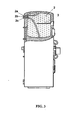
- the central heating system for premises and sanitary water with a combined central heating furnace presented as a cross-section, included in the central heating system, is shown in Figure 1 .
- the basic form of the furnace includes a cylindrical boiler 1 whereof the size depends on the envisaged power.
- the boiler 1 is provided with an immersive heat accumulator 2 and/or sanitary water boiler with three specially shaped connections 2a, 2b, 2c, as well as provided with an electric heating element 3 for supplementary sanitary water heating and/or provision of heated sanitary water whenever the whole furnace is out of operation.
- the boiler 1 contains two combustion chambers an upper combustion chamber 4 and a lower combustion chamber 5 the upper intended for combustion of liquid or gaseous fuels and the lower for combustion of the biological fuel.
- the upper combustion chamber 4 and the lower combustion chamber 5 are of cylindrical shape, which provides for good heat convection in the furnace.
- the cylindrical shape has been selected in order to minimize internal tensions in the material - the stainless sheet metal.
- the stainless sheet metal guarantees long-term operation of the furnace without any technological corrections.
- the cylindrical shape of the combustion chambers allows for easy and thorough cleaning.
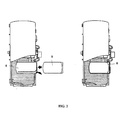
- the lower combustion chamber 5 for combustion of the biological fuel also includes a detachable grid 5a that shall be removed whenever we stop using the biological fuel and we choose to use the accumulator-type exchangeable insert 6.
- the inner side of the cover is provided with a routing valve intended for routing the primary combustion air under the combustion grid.
- a routing valve intended for routing the primary combustion air under the combustion grid.
- the combined central heating furnace is connected through the solar system pipe branching 7 to the solar energy receiver system 8 as well as to the combined expansion tank 9 with the compressed-air compensation duct 10.
- the upper combustion chamber 4 contains an externally adjustable ejector-type attachment 11, an adjustable chimney insert 12 for routing the exit of exhaust gases into the chimney, as well as a detachable spiral insert 13 for re-routing the exhaust gases.
- the accumulation-type exchangeable insert 6 is designed for the period when the heat is not derived from biological fuel. It is very useful to use solar energy and the accumulation-type exchangeable insert 6 at a time, which adds to the total mass of the heat carrier (water).
- the water provided with higher specific heat than the air, absorbs the heat at the time of its intensive production and accumulates it accordingly. Intensive and excessive heat production takes place at intensive solar radiation when the heat absorption exceeds its consumption.
- the accumulated heat provides for compensation of thermal oscillations between the production and the consumption. More accumulated heat contributes to higher utilization rate of the furnace and in particular of the entire heating system. A furnace provided with such insert takes priority over traditional central heating furnaces.
- the accumulation-type exchangeable insert 6 is made of stainless steel metal, is of cylindrical shape and fits snuggly into the cylindrical combustion chamber of the central heating furnace for premises and sanitary water. Appropriate mounting of the accumulation-type exchangeable insert 6 results in a minimum air gap, which guarantees good passage of the heat from the heat carrier in the central heating furnace to the heat carrier in the accumulation-type exchangeable insert 6.
- the latter is insulated at the front, which prevents from thermal loss into the environment.
- the accumulation-type exchangeable insert 6 shall get filled with the accumulation liquid (water) only when mounted in its place. In this way we avoid any moving of heavy burdens. Its mounting meets all ergonomic requirements for user-friendly and safe handling. There is only one way of mounting where all mistakes are excluded.
- the immersive heat accumulator 2 and/or the boiler is immersed into the upper part of the boiler 1.
- the size and the shape of the heat accumulator 2 are adjusted and optimized to the boiler.
- the mounting of the heat accumulator 2 provides for optimum supplementary heating of sanitary water as well as for harmonized monitoring of the heated sanitary water consumption.
- the depth of the immersion of the heat accumulator 2 into the boiler 1 is adjusted to the optimum hot sanitary water consumption, depending on the built-in materials and the thermal power of the boiler 1.
- the share of the heat accumulator that makes contact with the primary heating water in the boiler 1 is adjusted to the intensity of the heat passage from the heat carrier in the central heating system through the heat accumulator 2 wall to the heated sanitary water. Partial immersion of the heat accumulator 2 into the boiler 1 refrains from excessive heat emission in case of intensive sanitary water consumption on account of dynamic responses with reference to the whole heating system referred to in this invention.
- the heat accumulator 2 is immersed into the boiler 1 for 45% of the height of the heat accumulator.
- the surface of the heat accumulator that makes contact with the primary water in the boiler 1 is adjusted to the required quantity of heat that passes from the boiler 1 into the heat accumulator 2.
- the 45 % immersion is adjusted to the intensity of the convection that occurs at usual sanitary water consumption at normal heating of one-family houses.
- the heat accumulator 2 is of cylindrical shape that minimizes internal tensions in the material - stainless sheet metal. Stainless sheet metal guarantees long-term operation.
- connections 2a, 2b and 2c that continue internally into pipes as follows:
- the 55% height of the heat accumulator 2, that is not immersed into the boiler, is surrounded by a 120 mm insulating layer that prevents from the loss of the heat of the already heated sanitary water.
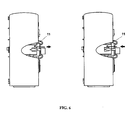
- the pipes mounted in the pipe branching 7 and shown in Figure 4 , that lead to/from solar energy receivers 8, are made from copper, have different diameters and different thermal insulation.
- the pipe branching 7 of the inflow and outflow pipes system is tied into a sheath for two reasons. The first reason: easier and more solid mounting, the second reason: recuperative effect of the pipe branching 7.
- the emitted heat is received by a cold pipe that pre-heats the heat carrier and contributes to the final utilization rate of the entire system.
- the pipe branching 7 includes four pipes as follows:
- the warm pipe contains sufficient hot heat carrier that emits the heat on its way to the furnace, thereby pre-heating the heat carrier traveling into the solar energy receivers 8.
- the tiniest pipe C provides for compressed-air compensation and functions at the same time as a circulation duct supplying the air-compression tank with minimum gravitation flow.
- the medium flowing along the tiniest pipe C maintains positive temperatures in the thermally exposed expansion tank 9. Airing of the boiler 1 also uses the pipe branching 7 of the solar system.
- the combined expansion tank 9 is adapted for use in the heating system referred to in this invention.
- the expansion tank 9 is of open type, providing for generation of the pressure in the heating system, for accumulation of the withdrawing water from the solar and from the heating systems, and functioning as an overheating valve. It is mounted at least 500 mm above the upper level of the highest heater and at least 200 mm under the lowest level of solar energy receivers 8.
- the pump drives the water through solar energy receivers 8 and transports it through the combined expansion tank 9, wherefrom the water returns back into the boiler 1 of the central heating furnace referred to in this invention.
- the combined expansion tank 9 is open, provided on top with a compressed-air compensation opening. Airing of the whole system is simplified and no special airing valve is needed.
- the combined expansion tank 9 is designed for compressed-air compensation in the solar and heating systems.
- the heat carrier is integral and flows through the solar and the heating systems.
- the safety overflow pipe 10 is connected to the combined expansion tank 9 immediately under its cover.
- the pipe leads from the expansion tank into the cellar of the building wherefrom it is routed to the outflow.
- the level rises until it attains the overflow duct.
- the excessive liquid passes over the overflow duct and indicates that the system is filled with the heat carrier.
- the operation of a combined expansion tank 9 requires no additional power supply.
- the water circulates in the system by means of a system pump that lies close to the central heating furnace.
- the flow guarantees the heating of the expansion tank 9 even during the most unfavourable weather conditions - low temperatures around the expansion tank 9. Due to this specific characteristic there can not come to any water freezing that could prevent from smooth system operation. Water tends to withdraw from the solar system whenever the circumstances for heat rising turn out unfavourable (no solar radiation, low temperatures, temperatures in solar energy receivers 8, lower temperatures in the boiler 1 etc.).
- the secured positive temperature difference provides for system operation under favourable conditions, which in turn indirectly increases the utilization rate of the total system operation.
- connection 10 for the pipe along which water flows from solar energy receivers 8.
- underpressure may occur at a particular moment due to oscillations of water level in the expansion tank 9. In such case it may occur that due to the developed subpressure the walls of the expansion tank 9 may suffer deformation.
- the airing pipe provides a capillary link of the system with the environment and secures random compressed-air compensation.
- the pipe for connection of the reverse duct from solar energy receivers 8 On the top of the expansion tank, there is the pipe for connection of the reverse duct from solar energy receivers 8. At the connection point, the pipe diameter is 12 mm and subsequently it extends to 14 mm.
- the airing pipe is mounted on the extended part of the pipe under an acute angle (10° with reference to the vertical).
- the internal diameter of the pipe measures 4 mm and provides capillary connection of the system with the environment. The connection is necessary for compressed-air compensation at extremely fast system filling and discharging (fast circulation of the heat carrier in the system).
- the capillary pipe provides for additional airing during the system filling itself.
- the spiral insert 13 provides for rerouting of exhaust gases tangentially to the combustion chamber.
- the cross flow established between exhaust gases and the heat carrier in the boiler provides for the maximum thermal transmittivity. In case of absence of the spiral insert 13 the heat spreads in layers, which results in lower heating of the heat carrier due to lower thermal transmittivity.
- the spiral insert 13 fits snuggly into the circular gap between the external cladding of the boiler 1 and the internal cladding of the furnace.
- the spiral insert 13 extends up to the vertical link between the upper combustion chamber 4 and the rest of the furnace.
- the spiral insert 13 is detachable and may be removed whenever required, in order to clean the circular exhaust gas channel.
- the burning products leave the combustion chamber in the form of non-burned particles. If providing for hot direct burning-process environment, we thereby provide additional thermal power that intensifies the burning of the incoming fuel.
- the ejector attachment 11 we provide for absorption of additional surrounding air in the direct burning process. Due to more intensive burning and due to higher burning temperatures, the process is manifested as a blue flame. In order to obtain a blue flame it is necessary to create appropriate burning conditions influenced by the selection of the fuel injection nozzle and by the correct position of the ejector attachment 11.
- the ejector attachment 11 is adjustable from the outer side of the boiler.
- the support of the guide for the ejector attachment 11 is mounted on the water-cooled cast-iron door of the upper combustion chamber 4.
- the guide including the ejector attachment 11 is adjustable along the depth of the upper combustion chamber 4.
- the setting of the ejector attachment 11 may undergo optimization during the very operation of the boiler 1.
- the ejector attachment 11 provides for adjustment to optimum burning conditions for different starting conditions.
- the starting condition denotes in particular the application of different types of burners and/or different nozzle diameters.
- the guide of the ejector attachment 11 is suitable for guiding the guide from the outer side of the boiler 1 - even during the operation of the burner. Thereby the attachment allows for adjustment of the attachment to the depth and to the intensity of the flame, thermal power and uniform heat distribution within the upper combustion chamber 4.
- the ejector attachment 11 is of universal type and may match particular construction components.
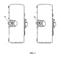
- the adjustable chimney insert 12 is mounted at the back of the combustion chamber; it is mobile and adjustable along the axis
- the adjustable chimney insert 12 is made of stainless sheet metal and it serves for routing the exiting exhaust gases into the chimney. Due to the mounted chimney insert 12 the exhaust gases are forced to exit from the bottom of the upper combustion chamber 4. The longer travelled way by the exiting exhaust gases contributes to an increased integral heat emission to the heat carrier in the boiler, which in turn increases the utilization rate of the boiler.
- the insert 12 may also be removed in order to enable easy and thorough cleaning of burning residuals.
- the chimney insert 12 is shaped as a sheet metal pipe with 1/3 of the pipe cladding open at the bottom side.
- the insert 12 forms the cladding of the pipe that from the upper side prevents from direct access of exhaust gases from the boiler into the chimney.
- the two-thirds limitation from the upper side causes some forced counter-gravitation flow of exhaust gases that have tn enter the chimney from the lower 1/3 open side.
- the prolonged way of exhaust gases causes additional cooling down and heat emission to the heat carrier in the system (water).
- the adjustable chimney insert 12 also provides for draught control.
- the chimney insert 12 can be removed from the back wall of the upper combustion chamber 4 in order to release direct passage to exhaust gases. The resistance to the flow of exhaust gases is reduced and the direct flow is more intensive due to lower resistances.
- the adjustable chimney insert 12 may be removed and pulled out through the exhaust pipe (at tho back of the boiler), which provides for easier cleaning.
Landscapes
- Engineering & Computer Science (AREA)
- Mechanical Engineering (AREA)
- General Engineering & Computer Science (AREA)
- Chemical & Material Sciences (AREA)
- Combustion & Propulsion (AREA)
- Physics & Mathematics (AREA)
- Thermal Sciences (AREA)
- Life Sciences & Earth Sciences (AREA)
- Sustainable Development (AREA)
- Sustainable Energy (AREA)
- Heat-Pump Type And Storage Water Heaters (AREA)
Claims (9)
- Un système de chauffage central pour locaux et eau chaude sanitaire composé d'une chaudière avec un chauffe-eau (1) alimenté par le haut par un accumulateur de chaleur à immersion (2) ou un chauffe-eau sanitaire doté de trois raccords de forme spéciale (2a, 2b, 2c), également alimenté par un élément de chauffage électrique (3), la chaudière étant raccordée par un tuyau de raccordement de système solaire (7) à un système de captage de l'énergie solaire (8) ainsi qu'à un vase d'expansion combiné (9) avec une conduite de compensation à air comprimé (10), caractérisé en ce que le système de chauffage central comporte un chauffe-eau (1) avec une chambre de combustion supérieure (4), une chambre de combustion inférieure (5) et un insert de type accumulateur, ladite chambre de combustion inférieure étant adaptée pour pouvoir être remplacée par ledit insert de type accumulateur (6) qui est rempli de fluide d'accumulation et a une forme cylindrique qui s'adapte exactement à la forme cylindrique de la chambre de combustion inférieure (5).
- Le système de chauffage central pour locaux et eau sanitaire selon la revendication 1, caractérisé en ce que l'accumulateur de chaleur (2) est à immersion, plongé à 45 % de sa hauteur dans la partie supérieure du chauffe-eau (1) et relié au système par les raccords (2a, 2b, 2c), où le raccord (2a) est prolongé par le tuyau qui mène sous le sommet de l'accumulateur de chaleur (2), est légèrement courbé et se termine juste en dessous du sommet de l'accumulateur de chaleur avec un espace libre de 10 mm, le raccord (2b) est prolongé par le tuyau qui mène directement à l'intérieur de l'accumulateur de chaleur (2) pour le raccordement de la conduite de circulation, et le raccord (2c) se poursuit par le tuyau qui mène au bas de l'accumulateur de chaleur (2), est fortement courbé et se termine légèrement au-dessus du bas de l'accumulateur de chaleur (2) avec un espace libre de 10 mm.
- Le système de chauffage central pour locaux et eau chaude sanitaire selon la revendication (1), caractérisé en ce que les tuyaux reliant le chauffe-eau (1) de la chaudière aux capteurs d'énergie solaire (8) sont montés dans le raccordement du tuyau (7), et ont des diamètres différents et des isolations différentes : le tuyau (A) allant du chauffe-eau (1) aux capteurs d'énergie solaire (8), a un diamètre interne de 13 mm et n'est pas isolé ; le tuyau (B) allant des capteurs d'énergie solaire (8) au chauffe-eau (1) a un diamètre interne de 13 mm, il est gainé et donc partiellement isolé ; le tuyau (C) de la conduite de circulation qui relie le sommet de la partie chauffante de la chaudière à la partie inférieure du vase d'expansion (9) a un diamètre interne de 4 mm et est isolé ; le tuyau (D) n'est pas isolé.
- Le système de chauffage central pour locaux et eau sanitaire selon les revendications 1 et 4, caractérisé en ce que le raccordement du tuyau (7) sert également à l'aération du chauffe-eau (1).
- Le système de chauffage central pour locaux et eau sanitaire selon la revendication 1, caractérisé en ce que le vase d'expansion combiné (9) est de type ouvert et est monté au moins 500 mm au-dessus du niveau supérieur du chauffage le plus haut et au moins 200 mm au-dessous du niveau inférieur des capteurs d'énergie solaire (8), un tuyau d'écoulement de sécurité étant raccordé immédiatement sous son couvercle, tandis que le côté inférieur est doté d'un raccord pour la conduite de circulation alimentant le chauffe-eau en air (1).
- Le système de chauffage central pour locaux et eau sanitaire selon les revendications 1 et 6, caractérisé en ce que le sommet du vase d'expansion est doté d'un raccord pour la conduite de retour des capteurs d'énergie solaire (8); de 12 mm de diamètre au point de raccordement avec le tuyau et s'élargissant ensuite à 14 mm, et en ce que le tuyau d'aération est monté sur la partie élargie du tuyau selon un angle aigu de -10° par rapport à la verticale, que son diamètre interne est de 4 mm et qu'il assure un raccordement capillaire du système avec l'environnement, et qu'il assure également une aération supplémentaire au niveau du remplissage du système lui-même.
- Le système de chauffage central pour locaux et eau sanitaire selon la revendication 1, caractérisé en ce que la chaudière contient un insert hélicoïdal amovible (13) qui se place exactement dans l'espace circulaire entre l'enveloppe du chauffe-eau (1) et l'enveloppe interne de la chaudière, et en ce qu'il s'élargit vers le haut jusqu'à la liaison entre la chambre de combustion supérieure (4) et le reste de la chaudière.
- Le système de chauffage central pour locaux et eau sanitaire selon la revendication 1, caractérisé en ce que la chambre de combustion supérieure (4) est alimentée depuis l'extérieur du chauffe-eau par une fixation d'éjecteur réglable (11) de sorte que le support du guide de la fixation de l'éjecteur (11) est monté sur la porte en fonte à refroidissement par eau de la chambre de combustion supérieure (4) et le guide comportant la fixation de l'éjecteur (11) est réglable le long de la profondeur de la chambre de combustion supérieure (4).
- Le système de chauffage central pour locaux et eau sanitaire selon la revendication 1, caractérisé en ce qu'à l'arrière de la chambre de combustion supérieure (4), l'insert de cheminée (12) a été monté de façon réglable sous la forme d'un tuyau de tôle dont le tiers inférieur de la gaine est ouvert, où l'insert (12) forme la gaine du tuyau qui empêche l'accès direct depuis le haut des gaz d'échappement du chauffe-eau dans la cheminée, tandis que les deux-tiers supérieurs du tuyau provoquent un flux de fumées opposé à la gravitation, lequel doit entrer dans la cheminée par le tiers ouvert du côté inférieur.
Applications Claiming Priority (2)
| Application Number | Priority Date | Filing Date | Title |
|---|---|---|---|
| SI200300159A SI21518B (sl) | 2003-06-27 | 2003-06-27 | Sistem za centralno ogrevanje prostorov in sanitarne vode |
| PCT/SI2004/000024 WO2005001343A2 (fr) | 2003-06-27 | 2004-06-23 | Systeme de chauffage central pour local et eau chaude sanitaire |
Publications (2)
| Publication Number | Publication Date |
|---|---|
| EP1642067A2 EP1642067A2 (fr) | 2006-04-05 |
| EP1642067B1 true EP1642067B1 (fr) | 2013-02-13 |
Family
ID=33550675
Family Applications (1)
| Application Number | Title | Priority Date | Filing Date |
|---|---|---|---|
| EP04749270A Expired - Lifetime EP1642067B1 (fr) | 2003-06-27 | 2004-06-23 | Systeme de chauffage central pour local et eau chaude sanitaire |
Country Status (3)
| Country | Link |
|---|---|
| EP (1) | EP1642067B1 (fr) |
| SI (1) | SI21518B (fr) |
| WO (1) | WO2005001343A2 (fr) |
Family Cites Families (1)
| Publication number | Priority date | Publication date | Assignee | Title |
|---|---|---|---|---|
| AU2766797A (en) | 1996-04-26 | 1997-11-19 | Promed Ag | Low temperature heating system |
-
2003
- 2003-06-27 SI SI200300159A patent/SI21518B/sl active Search and Examination
-
2004
- 2004-06-23 WO PCT/SI2004/000024 patent/WO2005001343A2/fr not_active Ceased
- 2004-06-23 EP EP04749270A patent/EP1642067B1/fr not_active Expired - Lifetime
Also Published As
| Publication number | Publication date |
|---|---|
| SI21518B (sl) | 2013-07-31 |
| WO2005001343A2 (fr) | 2005-01-06 |
| WO2005001343A3 (fr) | 2005-06-30 |
| EP1642067A2 (fr) | 2006-04-05 |
| SI21518A (sl) | 2004-12-31 |
Similar Documents
| Publication | Publication Date | Title |
|---|---|---|
| US4823770A (en) | Combination hydronic space heater and tankless hot water heater | |
| US4747447A (en) | Heat exchanger | |
| US4899696A (en) | Commercial storage water heater process | |
| RU2452906C2 (ru) | Котел для отопления и горячего водоснабжения, теплообменник котла, буферная емкость котла и способ работы котла | |
| EA006357B1 (ru) | Система для нагрева жидкостей | |
| US5273209A (en) | Heat exchange and fuel feed apparatus for vertical furnace | |
| RU2334919C1 (ru) | Водяной отопительный котел | |
| EP1642067B1 (fr) | Systeme de chauffage central pour local et eau chaude sanitaire | |
| KR100776971B1 (ko) | 연탄 겸용 기름 보일러 | |
| RU142739U1 (ru) | Отопительный котел | |
| CN202792500U (zh) | 一种热管式燃气常压热水锅炉 | |
| US20080105755A1 (en) | High-thermal-mass hydronic furnace | |
| KR19990076959A (ko) | 가열 장치 및 그 작동 방법 | |
| RU100594U1 (ru) | Котел для отопления и горячего водоснабжения, теплообменник котла и буферная емкость котла | |
| CN216667751U (zh) | 一种热反射盘及应用该热反射盘的商用炉灶 | |
| RU2362093C1 (ru) | Водогрейный котел | |
| US6561182B2 (en) | Water heater, steam generator and gas burner therefor | |
| FI77526C (fi) | Centralvaermepanna. | |
| KR101773712B1 (ko) | 가스 재순환 무연통 난로 | |
| GB2360571A (en) | Recirculation circuit and cold water connection arrangement for a water heater | |
| RU2133413C1 (ru) | Водогрейный котел | |
| EP0198836A1 (fr) | Chaudiere a gaz a immersion | |
| CA1288297C (fr) | Chauffe-eau commercial a reservoir de stockage | |
| RU99117U1 (ru) | Котел отопительный водогрейный чугунный газовый | |
| EP0608030A1 (fr) | Chaudière combinée à trois voies |
Legal Events
| Date | Code | Title | Description |
|---|---|---|---|
| PUAI | Public reference made under article 153(3) epc to a published international application that has entered the european phase |
Free format text: ORIGINAL CODE: 0009012 |
|
| 17P | Request for examination filed |
Effective date: 20060116 |
|
| AK | Designated contracting states |
Kind code of ref document: A2 Designated state(s): AT BE BG CH CY CZ DE DK EE ES FI FR GB GR HU IE IT LI LU MC NL PL PT RO SE SI SK TR |
|
| AX | Request for extension of the european patent |
Extension state: HR MK |
|
| RAX | Requested extension states of the european patent have changed |
Extension state: HR Payment date: 20060106 Extension state: MK Payment date: 20060106 |
|
| 17Q | First examination report despatched |
Effective date: 20100727 |
|
| GRAP | Despatch of communication of intention to grant a patent |
Free format text: ORIGINAL CODE: EPIDOSNIGR1 |
|
| GRAS | Grant fee paid |
Free format text: ORIGINAL CODE: EPIDOSNIGR3 |
|
| GRAA | (expected) grant |
Free format text: ORIGINAL CODE: 0009210 |
|
| AK | Designated contracting states |
Kind code of ref document: B1 Designated state(s): AT BE BG CH CY CZ DE DK EE ES FI FR GB GR HU IE IT LI LU MC NL PL PT RO SE SI SK TR |
|
| AX | Request for extension of the european patent |
Extension state: HR MK |
|
| REG | Reference to a national code |
Ref country code: GB Ref legal event code: FG4D |
|
| REG | Reference to a national code |
Ref country code: AT Ref legal event code: REF Ref document number: 596705 Country of ref document: AT Kind code of ref document: T Effective date: 20130215 |
|
| REG | Reference to a national code |
Ref country code: IE Ref legal event code: FG4D |
|
| REG | Reference to a national code |
Ref country code: DE Ref legal event code: R096 Ref document number: 602004040973 Country of ref document: DE Effective date: 20130411 |
|
| REG | Reference to a national code |
Ref country code: AT Ref legal event code: MK05 Ref document number: 596705 Country of ref document: AT Kind code of ref document: T Effective date: 20130213 |
|
| REG | Reference to a national code |
Ref country code: NL Ref legal event code: VDEP Effective date: 20130213 |
|
| PG25 | Lapsed in a contracting state [announced via postgrant information from national office to epo] |
Ref country code: SE Free format text: LAPSE BECAUSE OF FAILURE TO SUBMIT A TRANSLATION OF THE DESCRIPTION OR TO PAY THE FEE WITHIN THE PRESCRIBED TIME-LIMIT Effective date: 20130213 Ref country code: BG Free format text: LAPSE BECAUSE OF FAILURE TO SUBMIT A TRANSLATION OF THE DESCRIPTION OR TO PAY THE FEE WITHIN THE PRESCRIBED TIME-LIMIT Effective date: 20130513 Ref country code: CY Free format text: LAPSE BECAUSE OF FAILURE TO SUBMIT A TRANSLATION OF THE DESCRIPTION OR TO PAY THE FEE WITHIN THE PRESCRIBED TIME-LIMIT Effective date: 20130213 Ref country code: AT Free format text: LAPSE BECAUSE OF FAILURE TO SUBMIT A TRANSLATION OF THE DESCRIPTION OR TO PAY THE FEE WITHIN THE PRESCRIBED TIME-LIMIT Effective date: 20130213 Ref country code: ES Free format text: LAPSE BECAUSE OF FAILURE TO SUBMIT A TRANSLATION OF THE DESCRIPTION OR TO PAY THE FEE WITHIN THE PRESCRIBED TIME-LIMIT Effective date: 20130524 |
|
| PG25 | Lapsed in a contracting state [announced via postgrant information from national office to epo] |
Ref country code: BE Free format text: LAPSE BECAUSE OF FAILURE TO SUBMIT A TRANSLATION OF THE DESCRIPTION OR TO PAY THE FEE WITHIN THE PRESCRIBED TIME-LIMIT Effective date: 20130213 Ref country code: PL Free format text: LAPSE BECAUSE OF FAILURE TO SUBMIT A TRANSLATION OF THE DESCRIPTION OR TO PAY THE FEE WITHIN THE PRESCRIBED TIME-LIMIT Effective date: 20130213 Ref country code: GR Free format text: LAPSE BECAUSE OF FAILURE TO SUBMIT A TRANSLATION OF THE DESCRIPTION OR TO PAY THE FEE WITHIN THE PRESCRIBED TIME-LIMIT Effective date: 20130514 Ref country code: PT Free format text: LAPSE BECAUSE OF FAILURE TO SUBMIT A TRANSLATION OF THE DESCRIPTION OR TO PAY THE FEE WITHIN THE PRESCRIBED TIME-LIMIT Effective date: 20130613 Ref country code: SI Free format text: LAPSE BECAUSE OF FAILURE TO SUBMIT A TRANSLATION OF THE DESCRIPTION OR TO PAY THE FEE WITHIN THE PRESCRIBED TIME-LIMIT Effective date: 20130213 Ref country code: FI Free format text: LAPSE BECAUSE OF FAILURE TO SUBMIT A TRANSLATION OF THE DESCRIPTION OR TO PAY THE FEE WITHIN THE PRESCRIBED TIME-LIMIT Effective date: 20130213 |
|
| PG25 | Lapsed in a contracting state [announced via postgrant information from national office to epo] |
Ref country code: EE Free format text: LAPSE BECAUSE OF FAILURE TO SUBMIT A TRANSLATION OF THE DESCRIPTION OR TO PAY THE FEE WITHIN THE PRESCRIBED TIME-LIMIT Effective date: 20130213 Ref country code: RO Free format text: LAPSE BECAUSE OF FAILURE TO SUBMIT A TRANSLATION OF THE DESCRIPTION OR TO PAY THE FEE WITHIN THE PRESCRIBED TIME-LIMIT Effective date: 20130213 Ref country code: NL Free format text: LAPSE BECAUSE OF FAILURE TO SUBMIT A TRANSLATION OF THE DESCRIPTION OR TO PAY THE FEE WITHIN THE PRESCRIBED TIME-LIMIT Effective date: 20130213 Ref country code: CZ Free format text: LAPSE BECAUSE OF FAILURE TO SUBMIT A TRANSLATION OF THE DESCRIPTION OR TO PAY THE FEE WITHIN THE PRESCRIBED TIME-LIMIT Effective date: 20130213 Ref country code: DK Free format text: LAPSE BECAUSE OF FAILURE TO SUBMIT A TRANSLATION OF THE DESCRIPTION OR TO PAY THE FEE WITHIN THE PRESCRIBED TIME-LIMIT Effective date: 20130213 Ref country code: SK Free format text: LAPSE BECAUSE OF FAILURE TO SUBMIT A TRANSLATION OF THE DESCRIPTION OR TO PAY THE FEE WITHIN THE PRESCRIBED TIME-LIMIT Effective date: 20130213 |
|
| PLBE | No opposition filed within time limit |
Free format text: ORIGINAL CODE: 0009261 |
|
| STAA | Information on the status of an ep patent application or granted ep patent |
Free format text: STATUS: NO OPPOSITION FILED WITHIN TIME LIMIT |
|
| PG25 | Lapsed in a contracting state [announced via postgrant information from national office to epo] |
Ref country code: IT Free format text: LAPSE BECAUSE OF FAILURE TO SUBMIT A TRANSLATION OF THE DESCRIPTION OR TO PAY THE FEE WITHIN THE PRESCRIBED TIME-LIMIT Effective date: 20130213 |
|
| REG | Reference to a national code |
Ref country code: DE Ref legal event code: R119 Ref document number: 602004040973 Country of ref document: DE |
|
| 26N | No opposition filed |
Effective date: 20131114 |
|
| PG25 | Lapsed in a contracting state [announced via postgrant information from national office to epo] |
Ref country code: MC Free format text: LAPSE BECAUSE OF FAILURE TO SUBMIT A TRANSLATION OF THE DESCRIPTION OR TO PAY THE FEE WITHIN THE PRESCRIBED TIME-LIMIT Effective date: 20130213 |
|
| REG | Reference to a national code |
Ref country code: CH Ref legal event code: PL |
|
| REG | Reference to a national code |
Ref country code: DE Ref legal event code: R097 Ref document number: 602004040973 Country of ref document: DE Effective date: 20131114 |
|
| GBPC | Gb: european patent ceased through non-payment of renewal fee |
Effective date: 20130623 |
|
| REG | Reference to a national code |
Ref country code: IE Ref legal event code: MM4A |
|
| REG | Reference to a national code |
Ref country code: DE Ref legal event code: R119 Ref document number: 602004040973 Country of ref document: DE Effective date: 20140101 |
|
| REG | Reference to a national code |
Ref country code: FR Ref legal event code: ST Effective date: 20140228 |
|
| PG25 | Lapsed in a contracting state [announced via postgrant information from national office to epo] |
Ref country code: IE Free format text: LAPSE BECAUSE OF NON-PAYMENT OF DUE FEES Effective date: 20130623 Ref country code: DE Free format text: LAPSE BECAUSE OF NON-PAYMENT OF DUE FEES Effective date: 20140101 Ref country code: CH Free format text: LAPSE BECAUSE OF NON-PAYMENT OF DUE FEES Effective date: 20130630 Ref country code: GB Free format text: LAPSE BECAUSE OF NON-PAYMENT OF DUE FEES Effective date: 20130623 Ref country code: LI Free format text: LAPSE BECAUSE OF NON-PAYMENT OF DUE FEES Effective date: 20130630 |
|
| PG25 | Lapsed in a contracting state [announced via postgrant information from national office to epo] |
Ref country code: FR Free format text: LAPSE BECAUSE OF NON-PAYMENT OF DUE FEES Effective date: 20130701 |
|
| PG25 | Lapsed in a contracting state [announced via postgrant information from national office to epo] |
Ref country code: TR Free format text: LAPSE BECAUSE OF FAILURE TO SUBMIT A TRANSLATION OF THE DESCRIPTION OR TO PAY THE FEE WITHIN THE PRESCRIBED TIME-LIMIT Effective date: 20130213 |
|
| PG25 | Lapsed in a contracting state [announced via postgrant information from national office to epo] |
Ref country code: HU Free format text: LAPSE BECAUSE OF FAILURE TO SUBMIT A TRANSLATION OF THE DESCRIPTION OR TO PAY THE FEE WITHIN THE PRESCRIBED TIME-LIMIT; INVALID AB INITIO Effective date: 20040623 Ref country code: LU Free format text: LAPSE BECAUSE OF NON-PAYMENT OF DUE FEES Effective date: 20130623 |