EP1642087B1 - Verfahren und vorrichtung zur automatischen detektierung und abbildung, insbesondere für vegetationslose bereiche - Google Patents
Verfahren und vorrichtung zur automatischen detektierung und abbildung, insbesondere für vegetationslose bereiche Download PDFInfo
- Publication number
- EP1642087B1 EP1642087B1 EP04745201A EP04745201A EP1642087B1 EP 1642087 B1 EP1642087 B1 EP 1642087B1 EP 04745201 A EP04745201 A EP 04745201A EP 04745201 A EP04745201 A EP 04745201A EP 1642087 B1 EP1642087 B1 EP 1642087B1
- Authority
- EP
- European Patent Office
- Prior art keywords
- image
- images
- nir
- vegetation
- reflectance
- Prior art date
- Legal status (The legal status is an assumption and is not a legal conclusion. Google has not performed a legal analysis and makes no representation as to the accuracy of the status listed.)
- Expired - Lifetime
Links
- 238000000034 method Methods 0.000 title claims abstract description 67
- 238000013507 mapping Methods 0.000 title claims abstract description 14
- 230000003595 spectral effect Effects 0.000 claims abstract description 39
- 239000002028 Biomass Substances 0.000 claims description 18
- 230000007423 decrease Effects 0.000 claims description 17
- 238000012545 processing Methods 0.000 claims description 12
- 238000001514 detection method Methods 0.000 claims description 11
- 230000000694 effects Effects 0.000 claims description 8
- 230000001932 seasonal effect Effects 0.000 claims description 8
- 239000002689 soil Substances 0.000 claims description 7
- 229910052500 inorganic mineral Inorganic materials 0.000 claims description 6
- 239000011707 mineral Substances 0.000 claims description 6
- 230000003287 optical effect Effects 0.000 claims description 5
- 230000008569 process Effects 0.000 claims description 4
- 230000009466 transformation Effects 0.000 claims description 3
- 230000004044 response Effects 0.000 abstract description 20
- 238000001228 spectrum Methods 0.000 abstract description 6
- 238000012731 temporal analysis Methods 0.000 abstract description 6
- ZPUCINDJVBIVPJ-LJISPDSOSA-N cocaine Chemical compound O([C@H]1C[C@@H]2CC[C@@H](N2C)[C@H]1C(=O)OC)C(=O)C1=CC=CC=C1 ZPUCINDJVBIVPJ-LJISPDSOSA-N 0.000 description 9
- 238000004458 analytical method Methods 0.000 description 6
- 238000002834 transmittance Methods 0.000 description 6
- 239000011435 rock Substances 0.000 description 4
- 230000004075 alteration Effects 0.000 description 3
- 238000005286 illumination Methods 0.000 description 3
- 240000007817 Olea europaea Species 0.000 description 2
- 239000005427 atmospheric aerosol Substances 0.000 description 2
- 238000004364 calculation method Methods 0.000 description 2
- 230000008859 change Effects 0.000 description 2
- 229930002875 chlorophyll Natural products 0.000 description 2
- 235000019804 chlorophyll Nutrition 0.000 description 2
- ATNHDLDRLWWWCB-AENOIHSZSA-M chlorophyll a Chemical compound C1([C@@H](C(=O)OC)C(=O)C2=C3C)=C2N2C3=CC(C(CC)=C3C)=[N+]4C3=CC3=C(C=C)C(C)=C5N3[Mg-2]42[N+]2=C1[C@@H](CCC(=O)OC\C=C(/C)CCC[C@H](C)CCC[C@H](C)CCCC(C)C)[C@H](C)C2=C5 ATNHDLDRLWWWCB-AENOIHSZSA-M 0.000 description 2
- 239000002131 composite material Substances 0.000 description 2
- 238000012937 correction Methods 0.000 description 2
- 238000011156 evaluation Methods 0.000 description 2
- 230000035945 sensitivity Effects 0.000 description 2
- XLYOFNOQVPJJNP-UHFFFAOYSA-N water Substances O XLYOFNOQVPJJNP-UHFFFAOYSA-N 0.000 description 2
- 238000007476 Maximum Likelihood Methods 0.000 description 1
- 238000010521 absorption reaction Methods 0.000 description 1
- 239000000443 aerosol Substances 0.000 description 1
- 239000003054 catalyst Substances 0.000 description 1
- 239000003795 chemical substances by application Substances 0.000 description 1
- 230000001427 coherent effect Effects 0.000 description 1
- 230000001186 cumulative effect Effects 0.000 description 1
- 238000010586 diagram Methods 0.000 description 1
- 238000009792 diffusion process Methods 0.000 description 1
- 235000013399 edible fruits Nutrition 0.000 description 1
- 230000006870 function Effects 0.000 description 1
- 238000010191 image analysis Methods 0.000 description 1
- 238000003384 imaging method Methods 0.000 description 1
- 238000012986 modification Methods 0.000 description 1
- 230000004048 modification Effects 0.000 description 1
- 238000000513 principal component analysis Methods 0.000 description 1
- 238000011158 quantitative evaluation Methods 0.000 description 1
- 230000005855 radiation Effects 0.000 description 1
- 238000005070 sampling Methods 0.000 description 1
- 230000003068 static effect Effects 0.000 description 1
- 239000005437 stratosphere Substances 0.000 description 1
- 239000000126 substance Substances 0.000 description 1
- CCEKAJIANROZEO-UHFFFAOYSA-N sulfluramid Chemical group CCNS(=O)(=O)C(F)(F)C(F)(F)C(F)(F)C(F)(F)C(F)(F)C(F)(F)C(F)(F)C(F)(F)F CCEKAJIANROZEO-UHFFFAOYSA-N 0.000 description 1
- 238000012546 transfer Methods 0.000 description 1
- 230000000007 visual effect Effects 0.000 description 1
Images



Classifications
-
- G—PHYSICS
- G01—MEASURING; TESTING
- G01C—MEASURING DISTANCES, LEVELS OR BEARINGS; SURVEYING; NAVIGATION; GYROSCOPIC INSTRUMENTS; PHOTOGRAMMETRY OR VIDEOGRAMMETRY
- G01C11/00—Photogrammetry or videogrammetry, e.g. stereogrammetry; Photographic surveying
- G01C11/04—Interpretation of pictures
- G01C11/06—Interpretation of pictures by comparison of two or more pictures of the same area
-
- G—PHYSICS
- G01—MEASURING; TESTING
- G01J—MEASUREMENT OF INTENSITY, VELOCITY, SPECTRAL CONTENT, POLARISATION, PHASE OR PULSE CHARACTERISTICS OF INFRARED, VISIBLE OR ULTRAVIOLET LIGHT; COLORIMETRY; RADIATION PYROMETRY
- G01J3/00—Spectrometry; Spectrophotometry; Monochromators; Measuring colours
- G01J3/28—Investigating the spectrum
- G01J3/30—Measuring the intensity of spectral lines directly on the spectrum itself
- G01J3/32—Investigating bands of a spectrum in sequence by a single detector
-
- G—PHYSICS
- G01—MEASURING; TESTING
- G01J—MEASUREMENT OF INTENSITY, VELOCITY, SPECTRAL CONTENT, POLARISATION, PHASE OR PULSE CHARACTERISTICS OF INFRARED, VISIBLE OR ULTRAVIOLET LIGHT; COLORIMETRY; RADIATION PYROMETRY
- G01J3/00—Spectrometry; Spectrophotometry; Monochromators; Measuring colours
- G01J3/28—Investigating the spectrum
- G01J3/30—Measuring the intensity of spectral lines directly on the spectrum itself
- G01J3/36—Investigating two or more bands of a spectrum by separate detectors
Definitions
- the present invention refers to an automatic method of detecting and mapping, particularly for burnt areas without vegetation, enabling, in a precise, simple, versatile, reliable, and efficient way, the discrimination of areas, in images acquired from satellite, where fires occurred on the basis of a comparison of images overcoming possible problems of dishomogeneity arising in the case when the conditions of acquisition of the images to be compared are different.
- the automatic mapping method is based on the multi-temporal analysis of multi spectral data, or on the changes in the spectral response of the Earth features in combined near infrared, or NIR (Near Infra-Red), and short wave infrared, or SWIR (Short Wave Infra-Red), or medium infrared, or MIR (Medium Infra-Red), windows of the electromagnetic spectrum.
- NIR Near Infra-Red
- SWIR Short Wave Infra-Red
- MIR Medium Infra-Red
- the present invention further refers to an apparatus performing such a method, which is simple, fast, and inexpensive.
- a spaceborne hot temperature event detection arrangement is described in document EP-A-1 048 928.
- Multi spectral radiometers are generally constituted by one or more passive optical sensors that register the radiance emitted by the Earth in various windows of the electromagnetic spectrum.
- the principal windows of the electromagnetic spectrum commonly used for land and vegetation analysis are the Visible (with wavelength from 0.4 ⁇ m to 0.7 ⁇ m, hereinafter referred to as VIS), the Near Infra-Red (with wavelength from 0.7 ⁇ m to 1.3 ⁇ m, hereinafter referred to as NIR), the Short Wavelength Infra-Red (with wavelength from 1.3 ⁇ m to 2.5 ⁇ m, hereinafter referred to as SWIR), the Medium Infra-Red (with wavelength from 2.5 ⁇ m to 4.5 ⁇ m, hereinafter referred to as MIR), and the Thermal Infra-Red (with wavelength up to 14.5 ⁇ m, hereinafter referred to as TIR).
- VIS Visible
- NIR Near Infra-Red
- SWIR Short Wavelength Infra-Red
- MIR Medium Infra-Red
- TIR Thermal Infra-Red
- Radiometers operating at these wavelengths are installed on airborne platforms - such as microlights, airplanes, balloons and dirigibles, operating between the ground free surface and the stratosphere - and spaceborne platforms, including all type of orbiting and sub-orbital spacecrafts at altitudes up to about 36.000 Km above the Earth's ground free surface.
- All the afore-said systems look at the Earth orthogonally to the direction of the platform's motion with an angle ranging from 0 to 35 degrees with respect to Nadir - that is, perpendicularly to the Earth.
- the aforementioned angle is called "Off Nadir".
- resolution cells or grids of the Earth surface can be generated with a spatial resolution (that is, the spacing of the elementary area, or pixel, within which it is possible to distinguish two objects) ranging from few centimetres to several kilometres.
- multi spectral radiometers are coherent imaging systems. This means that they allow measuring radiated energy of each Earth surface cell at different wavelengths, as well as measuring the difference in radiated energy between two independent cells in each wavelength.
- converting radiance in reflectance allows measuring the time variation in energy at each wavelength and in each Earth surface cell, and measuring the time variation of energy difference between two independent cells at each wavelength.
- Lp is the path radiance (that is the additional radiance due to the path in the atmosphere and hence to the diffusion or scattering phenomenon)
- E d is the downward irradiance
- E 0 is exo-atmospheric solar irradiance
- ⁇ z is the solar zenith angle.
- the atmospheric transmittance T v from the target toward the sensor depends on the off-nadir angle.
- the atmospheric transmittance T z in the illumination direction is a function of ⁇ z , and of the optical thickness to be accounted for in Rayleigh scattering and atmospheric aerosol effects.
- Radiance Lp can be evaluated by using the so-called Dark Object Subtraction or DOS method, which, as shown by P.S. Chavez in "An improved Dark-Object Subtraction Technique for Atmospheric Scattering Correction of Multispectral Data", Remote Sensing of the Environment 24, pp. 459-479, 1988, relies upon the hypothesis that some ground types - as some types of rocks and soils - behave as almost perfect "black bodies": in such cases, the associated reflectance measured at the satellite is almost entirely due to scattered path reflectance.
- Atmospheric radiative transfer codes ( Lowtran, Modtran, Code-6S, etc.) make use of standard atmosphere models, or of available measures of vertical atmosphere profiles, for determining the downward irradiance E d .
- the accuracy of atmospheric corrections for Rayleigh scattering and aerosol effects strictly depend upon the availability of data on atmosphere physical and chemical parameters at the precise time of the remote sensing image acquisition
- the fundamental key is to distinguish reflectance changes originated by illumination and atmospheric conditions, by sensor drift or by sensor differences, from reflectance changes due to decrease in biomass content, to chlorophyll absorption, to water content and to density in the vegetation cover.
- a method for separating changes due to intrinsic reflectance value of vegetation from changes due to other factors influencing the at-satellite reflectance is that of identifying "pseudo-invariant” features to be used as "reference targets” in cross-rectification of reflectance in different images. Identification of "pseudo-invariant" features requires accurate analysis of the whole of remote sensing data involved in the multi temporal analysis, following a linear radiometric transformation and aimed to implement relative reflectance retrieval. Accuracy of radiometric rectification strongly depends on the selection of pseudo-invariant features or of reference targets.
- mapping burnt areas starting from multi spectral remote sensing data were carried out on single date image analysis, on the basis of so-called Principal Components, band ratio or vegetation index, unsupervised or supervised classification clustering.
- use of a single remote sensing image for mapping burnt and de-vegetated areas does not allow these ones to be distinguished from urban areas, water surfaces, sparsely vegetated areas and rock outcrops.
- Multi-temporal methods based on the evaluation of changes of the spectral response between NIR and SWIR channels seem advantageous, since fire is an agent of land cover alteration, and therefore change detection methods reduce the likelihood of confusion with non vegetated or low vegetated static land cover types, such as urban areas, and rock outcrops
- NDVI index Normalized Difference Vegetation Index
- said one or more detection frequency channels may be at least two infrared channels, preferably a near infrared or NIR (Near Infra Red) channel, and a short wave infrared or SWIR (Short Wave Infra Red) channel, and/or a medium infrared or MIR (Medium Infra Red) channel.
- NIR Near Infra Red
- SWIR Short Wave Infra Red
- MIR Medium Infra Red
- Permanent Reflectors PRs may be determined as those resolution cells p xy which, in both images A i and A i +1 of the pair, have values of reflectance ⁇ in each one of said one or more channels which correspond to densely built urban areas, preferably presenting no or little vegetation with respect to the size of the resolution cells.
- said one or more first quantities depending on a variation, considered in steps C, D, F, and G, may comprise at least one quantity identically equal to the corresponding variation.
- said one or more first quantities depending on a variation, considered in steps C, D, F, and G comprise at least one percentage of the corresponding variation.
- said one or more second quantities depending on at least one reflectance ⁇ may comprise at least one quantity identically equal to the corresponding reflectance ⁇ of a channel.
- said one or more second quantities depending on at least one reflectance ⁇ may comprise at least one ratio between two reflectances ⁇ of two channels.
- the acquired data may comprise the radiance L of each one of the N images A i on each one of said one or more detection frequency channels
- the method before executing step B, may transforms the radiance L into the reflectance ⁇ for each one of said one or more channels, preferably taking account of the exo-atmospheric solar irradiance E 0 and of the effects of the sun zenith angle ⁇ z , and comprising the estimation of the path radiance L p , more preferably through the DOS method.
- the method takes vegetation seasonal differences into account.
- the method may take vegetation seasonal differences into account through the use of one or more corrective factors, preferably depending on the solar elevation angles ⁇ SEL_i and ⁇ SEL_ ( i+ 1) and/or on their difference ( ⁇ SEL_i - ⁇ SEL _( i +1) ) at the acquisition instants of the two images A i and A i +1 .
- the method executes steps L, M, and N only if the following checking step gives a positive outcome:
- step K checking that the two images A i and A i +1 of the pair have been acquired in periods of the year in which vegetation is in a comparable blooming condition, while in the case step K gives a negative outcome the following step is executed:
- Such radiometers used I the method according to the invention have at least two Infra-red channels, among which a NIR channel and a SWIR or MIR channel.
- the method discriminates: the set BA of resolution cells or pixels p xy of the image A i +1 , identified by coordinates ( xy ), corresponding to zones which have been subject to fire during the time interval between the acquisition of image A i and the acquisition of image A i +1 ; the set DB of resolution cells p xy of the image A i +1 corresponding to zones which have been subject to a decrease in biomass content or to an increase in soil or mineral cover during the time interval between the acquisitions of the two successive images A i and A i +1 ; and the set DV of resolution cells p xy of the image A i +1 corresponding to zones which have been subject to a loss of vegetation during the time interval between the acquisitions of the two successive images A i and A i +1 .
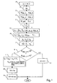
- the method identifies the three sets BA, DB, and DV in relation to pseudo invariant features or Permanent Reflectors, also indicated hereinafter as "PRs", by performing the steps illustrated in the following with reference to Figure 1.
- radiance L NIR of the NIR channel and radiance L SWIR of the SWIR channel are transformed, respectively, into reflectance p NIR and into reflectance ⁇ SWIR (and/or in reflectance ⁇ MIR ), respectively, preferably taking account of the exo-atmospheric solar irradiance E 0 and of the effects of the sun zenith angle ⁇ z , and estimating the path radiance L p , more preferably through the DOS method, still more preferably by employing equation [1].
- the resolution cells p xy of the N images A i are assumed as PRs.
- Such difference gives an estimation of the maximum difference of the cumulative contribution in atmospheric transmittance T v from the target towards the sensor, in atmospheric transmittance T z in the illumination direction, in optical thickness t R for Rayleigh scattering, and atmospheric aerosol effects E A .
- the percentage P xy of variation, from the i -th image A i to the time successive ( i +1)-th image A i +1 , of reflectances ⁇ specifically: the percentage P xy_NIR _ i of variation of the reflectance ⁇ NIR of pixel p xy in NIR channel, and the percentage P xy_NIR / SWIR_i (and/or P xy_NIR / MIR_i ) of variation of the ratio ⁇ NIR / ⁇ SWIR (and/or of the ratio ⁇ NIR / ⁇ MIR ) of the reflectances ⁇ NIR and ⁇ SWIR (and/or ⁇ MIR ) of pixel p xy in the NIR/SWIR channel ratio (and/or in the NIR/MIR channel ratio).
- step G it is determined a first set S 1 of resolution cells p xy of the image A i +1 corresponding to zones which have been subject to a decrease in biomass content or an increase in soil or mineral cover during the time interval between the acquisitions of the two successive images A i and A i+ 1 .
- the first set S 1 comprises the resolution cells p xy of the image A i +1 for which the percentages calculated in the sixth step F are lower than the difference ( M PR_Pi - ⁇ Pi ) calculated in the preceding step D in the corresponding channels of the response of the Permanent Reflectors PRs, calculated in the third step C.
- the first set S 1 comprises the pixels p xy for which the following inequalities are satisfied: P x ⁇ y - ⁇ N ⁇ I ⁇ R - ⁇ i ⁇ M P ⁇ R - ⁇ P - ⁇ N ⁇ I ⁇ R - ⁇ i - ⁇ P ⁇ R - ⁇ P - ⁇ N ⁇ I ⁇ R - ⁇ i , and P xy - NIR / SWIR - ⁇ i ⁇ M PR - ⁇ P - ⁇ NIR / SWIR - ⁇ i - ⁇ P ⁇ R - ⁇ P ⁇ ⁇ NIR / SWIR - ⁇ i and / or P xy - ⁇ NIR / MIR - ⁇ i ⁇ M PR - ⁇ P - ⁇ NIR / MIR - ⁇ i - ⁇ P ⁇ R - ⁇ P ⁇ NIR / SWIR -
- step H it is determined a second set S 2 of resolution cells p xy of the image A i +1 corresponding to zones which have been subject to a loss of vegetation during the time interval between the acquisitions of the two successive images A i and A i +1 .
- the second set S 2 comprises the pixels p xy for which the following inequalities are satisfied: ⁇ xy - NIR - ⁇ i + 1 ⁇ M PR - ⁇ ⁇ NIR - ⁇ i + 1 ⁇ xy - NIR - ⁇ SWIR - ⁇ i + 1 ⁇ M PR - ⁇ ⁇ NIR - ⁇ ⁇ SWIR - ⁇ i + 1 and / or ⁇ xy - ⁇ NIR - ⁇ MIR - ⁇ i + 1 ⁇ M PR - ⁇ ⁇ NIR - ⁇ ⁇ MIR - ⁇ i + 1 .
- step I it is determined a third set S 3 of resolution cells p xy of the image A i +1 corresponding to zones which have been subject to a damage during the time interval between the acquisitions of the two successive images A i and A i +1 .
- the set DB of the resolution cells p xy of the image A i +1 corresponding to zones which have been subject to a decrease in biomass content or to an increase in soil or mineral cover during the time interval between the acquisitions of the two successive images A i and A i +1 .
- a check is carried out for ascertaining whether the solar elevation angles ⁇ SEL_i and ⁇ SEL_ ( i+ 1) at the acquisition instants of the two images A i and A i +1 are both higher or both lower than a threshold value ⁇ .
- Such check assures that the two images A i and A i +1 have been acquired in periods of the year in which vegetation is in a comparable blooming condition, in order to grant reliability of mapping.
- Such check may be easily carried out by checking the following inequality: ⁇ SEL - ⁇ i - ⁇ * ⁇ SEL - ⁇ i + 1 - ⁇ > 0
- the method may comprise the use of corrective factors in calculations for determining the first set S 1 and/or the second set S 2 , corrective factors preferably depending on the solar elevation angles ⁇ SEL_i and ⁇ SEL_ ( i +1) , and possibly on their difference ( ⁇ SEL_i - ⁇ SEL_ ( i +1) ), at the acquisition instants of the two images A i and A i +1 .
- step K gives a positive outcome
- the three steps L, M and N are performed; otherwise, if the check of step K gives a negative outcome, step P is performed.
- step L it is determined, within the third set S 3 , a fourth set S 4 ⁇ S 3 of resolution cells p xy corresponding to zones wherein values of reflectance ⁇ xy of the preceding image A i identify them as cells corresponding to areas provided with "burnable" vegetation, such as forestry, agro-forestry, and semi-natural areas, and zones of permanent crops (preferably no zone is subject to human changes).
- step M it is determined the set BA of the resolution cells p xy of the image A i +1 corresponding to zones which have been subject to a fire during the time interval between the acquisition of the image A i and the acquisition of the image A i +1 .
- step N it is determined the set DV of the resolution cells p xy of the image A i +1 corresponding to zones which have been subject to a loss of vegetation during the time interval between the acquisitions of the two successive images A i and A i +1 .
- step P is performed, with which it is determined only the set DV of the resolution cells p xy of the image A i +1 corresponding to zones which have been subject to a loss of vegetation during the time interval between the acquisitions of the two successive images A i and A i +1 .
- the method comprises a further final step wherein the pixels p xy belonging to the set BA which are singly isolated from the other pixels of the set BA (or which belong to groups of pixels p xy of the set BA creating a zone having a reduced surface extension) are re-assigned to the set to which the surrounding pixels belong.
- This is done in order to reduce wrong assignments due to occurrence of limit values of reflectance or of the related statistical parameters used in calculations performed by the method and which may introduce evaluation ambiguities.
- this final step of the method may re-assign these pixels to the set BA. Similar processings may be carried out for the sets DB and DV.
- the method according to the invention enables estimating biomass content and vegetation cover from one date to another and ascertaining presence of areas which have been subject to loss of vegetation or fires during the same period.
- FIG 2 shows the so-called spectral reflectance signature ⁇ xy of 12 zones pertaining to different vegetation classes for two acquisition dates and the spectral response of the same zone after having burned.
- Data have been collected through satellite platform Landsat-5 TM.
- Landsat 5 TM channels number 1-5, and 7 are indicated as 1-6 in X coordinate, while the corresponding reflectance percentage is reported in Y coordinate.
- the wavelength interval of channels 1-5, and 7 are respectively 0.45-0.52 (Visible, or VIS, Blue), 0.53-0.61 (VIS-Green), 0.63-0.69 (VIS-Red), 0.78-0.90 (NIR), 1.55-1.75 (SWIR) and 2.09-2.35 (SWIR)
- the burned areas are obtained by a visual comparison of the September 12, 1997, and the August 30, 1998, Landsat 5 TM images, made by an operator, by using various RGB combination in order to visually enhance the vegetation alteration.
- Such areas which are sites of fire events reported in National Forest Guards and/or National Fire Brigades databases, are selected as unequivocally identified shapes of fire-damaged surfaces.
- Vegetation classes are indicated as land use Corine classes (according to the nomenclature of the known CORINE European project of coordinated information on the land use in the European context: COoRdinated INformation on the European Environment).
- the vegetation classes presenting a minimum of three distinct burned areas with a surface greater than 3 hectares are considered as fire-damaged areas.
- Resolution cells p xy situated in the inner central part of areas identified as fire-damaged have been selected and their associated reflectance percentages in channels 1-5, and 7 have been adopted as characteristic spectral signature of burnt area for the relevant vegetation class.
- spectral signatures of vegetated resolution cells on the two Landsat 5 images acquired on two different dates are different. This means that a quantitative evaluation of the damages occurred from one date to another by using multi-temporal analysis of remote sensing data can be performed only if the vegetation variation is calculated in relationship to a reference. Intrinsic reflectance spectral signature of this reference target homogeneoc!sly distributed over the whole remote sensing image must be independent from the acquisition date of the remote sensing data. Such reference targets are just the Permanents Reflectors PRs. The analysis of the vegetation variation from one date to another must be calculated by considering the distance from the vegetation spectral variation to the PRs spectral variation.
- the detection change from one date to another is decomposed in two components: one as representative of the variations due to difference of sensor sensitivity and radiometric range, to difference of wavelength centre value, to difference of up-welling and down-welling transmittance along the ground sensor path between the two image acquisition dates, and the second component as representative of the effective variation of the vegetation state between the two remote sensed image acquisition dates.
- the reflectance variation from vegetation to burned area is strictly related to the vegetation type and biomass content originally present, whereas the spectral signature of fire-damaged areas, on the post-fire image, appears slightly depending on the initial vegetation cover.
- the NIR reflectance decrease associated to fire damage is particularly significant for vegetal land classes characterised by the presence of trees and/or shrubs, such as: vineyards, fruit trees and olive groves (respectively identified as classes 221, 222, and 223 in the CORINE classification) or agro-forestry areas, transitional woodland and shrubs (respectively identified as classes 244, 323 and 324).
- the poorly defined class 242, including all complex cultivation patterns, is also characterised by a notable NIR reflectance decrease.
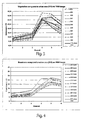
- Figure 3 shows the spectral reflectance signature in some Corine vegetation classes and the response from densely urbanised areas, always obtained in channels 1-5, and 7 of the satellite platform Landsat 5 TM radiometer. Said urban areas homogeneously distributed over the whole sensed image are considered as PRs.
- channels 1-5 and 7 of Landsat-5 TM are numbered as 1 to 6 in X coordinate.
- NIR reflectance percentage of PRs and reflectance percentage ratio in NIR/SWIR channels of PRs are lower than the corresponding values of the vegetation classes taken under consideration.
- Figure 4 shows some spectral reflectance signatures of the fire-damaged areas corresponding to the preceding Corine classes, considered in Figure 3, and the spectral response of densely urbanised areas PR areas, still obtained in channels 1-5, 7 (indicated with numbers 1 to 6 in X coordinate) through the satellite platform Landsat 5 TM.
- Figure 4 shows that fire-damaged areas have the same general form of spectra independently from the original vegetation cover class. Moreover, both NIR reflectance percentage of PRs and reflectance percentage ratio in NIR/SWIR channels of PRs are higher than the corresponding values of all fire-damaged areas, independently from the original vegetation cover class.
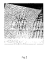
- Figure 5 represents a false colour image of Mount Etna acquired by means of the satellite platform SPOT-4 in channels NIRSWIR-RED on 7th June 2001.
- SPOT-4 borne multi spectral radiometer is characterised by four channels in the following wavelength intervals: 0.50-0.59 (VIS-Green), 0.61-0.68 (VIS-Red), 0.78-0.89 (NIR) and 1.58-1.75 (SWIR). Pixels size of SPOT images is equal to 20 meters* 20 meters.
- Figure 6 represents a false colour composite image of Mount Etna acquired by means of the satellite platform Landsat-7 in channels SWIR-NIR-RED on 29th July 2001.
- Landsat-7 borne radiometer pixels originally having size equal to 30 meters*30 meters, have been resized to pixels of size equal to 20 meters*20 meters with re-sampling method that does not alter the original land radiative spectrum.
- the two remote sensed images are acquired by two different multi-spectral radiometers, i.e. SPOT-4 (radiometer HRVIR-1) and Landsat-7 (radiometer ETM+), which are furthermore differen in radiometric response distribution, different in channel central wavelength, different in radiometric range, and different in pixel size.
- SPOT-4 radioometer HRVIR-1
- Landsat-7 radiometric ETM+
- the two remote sensed images are acquired in different seasons since the pre-fire image has been acquired in late spring at the beginning of June, when the vegetation is characterised by a high level of biomass content and ground coverage, whereas the post-fire image has been acquired in summer at the end of July, when the vegetation is characterized by high hydric stress. Due to seasonal changes, all vegetation Corine classes are characterised by a substantial decrease in both the biomass content and the vegetation cover.
- Figure 7 represents the image comprising resolution cells, of size equal to 20 meters*20 meters, classified through variation analysis as damaged vegetation cells, which are characterised by a decrease in percentage of biomass content (decrease in percentage of NIR reflectance value) and in vegetation cover (decrease in percentage of NIR/SWIR ratio) higher than the PRs spectral variation calculated between the two remote sensed images of 7th June 2001, acquired by SPOT-4, and 29th July 2001, acquired by Landsat 7 ETM+.
- PRs are dense urban areas, the spectral variation of which is assumed as representative of differences in sensor sensitivity and radiometric range, in wavelength centre value, or in response histogram in the wavelength interval of NIR and SWIR channels, in up-welling and down-welling transmittance along the ground sensor path between the two remote sensing images of 7th June 2001, acquired by SPOT-4, and 29th July 2001, acquired by Landsat 7 ETM+.
- the North-West part of the image is mainly occupied by evergreen forests and it can be noted that for pixels classified as damaged resolution cells from 7th June to 29th July, the decrease in biomass content and vegetation cover is principally due to seasonal changes occurring between spring and summer vegetation states.
- Figure 8 shows all the de-vegetated resolution cells present in the Landsat 7 ETM+ image acquired on 29th July 2001.
- Said resolution cells are characterised by biomass content (given by the NIR reflectance value) and vegetation cover (given by NIR/SWIR ratio) lower than the one of PRs (dense urban areas) on final remote sensing data Landsat 7 ETM+ of 29th July.
- PRs dense urban areas
- Figure 9 shows all the resolution cells wherein a decrease in biomass content and vegetation cover occurs from 7th June 2001 to 29th July 2001 and which are classified as de-vegetated resolution cells on 29th July 2001.
- the pixel clusters constituted by more than 10 pixels selected by both multi-temporal variation ( Figure 7) and post fire analysis ( Figure 8) are classified as fire damaged areas.
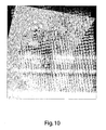
- Figure 10 represents the false colour composite image of 29th July 2001 acquired by Landsat-7 ETM + in channels SWIR-NIR-Blue overlaying the layer GIS of fire damaged surfaces larger than 1 hectare, defined in Figure 9.
Landscapes
- Physics & Mathematics (AREA)
- Spectroscopy & Molecular Physics (AREA)
- General Physics & Mathematics (AREA)
- Engineering & Computer Science (AREA)
- Multimedia (AREA)
- Radar, Positioning & Navigation (AREA)
- Remote Sensing (AREA)
- Image Processing (AREA)
- Mobile Radio Communication Systems (AREA)
- Stereo-Broadcasting Methods (AREA)
- Investigating Or Analysing Materials By Optical Means (AREA)
Claims (18)
- Automatisches Verfahren zum Erfassen und Abbilden insbesondere von verbrannten Bereichen ohne Vegetation in N Bildern Ai mit N ≥ 2, für i = 1, 2, ..., N, die aus Daten erhalten wurden, die während einer bestimmten Zeitspanne über demselben geographischen Bereich mit Mitteln eines oder mehrerer passiver Spektralradiometer auf einem oder mehreren Erfassungsfrequenzkanälen aufgenommenen wurden, wobei jedes Bild Ai eine gleiche Mehrzahl von Auflösungszellen oder Pixeln pxy umfasst, wobei die Reflexion ρ von jedem einzelnen des einen oder der mehreren Kanäle für jedes Bild verfügbar ist, dadurch gekennzeichnet, dass das Verfahren die folgenden Schritte umfasst:B. für jedes Paar von aufeinanderfolgenden Bildern Ai und A i+1, für i = 1, 2, ..., N-1: Annahme der Auflösungszellen pxy, die in beiden Bildern konstante optische und elektromagnetische Eigenschaften aufweisen, als permanente Reflektoren PRs;C. für jedes Paar von aufeinanderfolgenden Bildern Ai und Ai+1, für i = 1, 2, ..., N-1: Berechnen des Mittelwertes MPR_P_i und der Standardabweichung σPR_P_i von einer oder mehreren ersten Größen (P), die von der Variation von dem i-ten Bild Ai zu dem zeitlich nachfolgenden (i+1)-ten Bild Ai+1 einer oder mehreren zweiten Größen (ρNIR, ρNIR / ρSWIR, ρNIR / ρMIR ) abhängig sind, die von zumindest einer Reflexion ρ der permanenten Reflektoren PRs in dem einen oder den mehreren Kanälen abhängig sind;D. Berechnen der Differenz (MPR_Pi - σPi ) zwischen dem Mittelwert MPR_P_i und der Standardabweichung σPR_P_i, die in dem Schritt C berechnet wurden, für jede einzelne der einen oder mehreren ersten Größen (P);E. Berechnen der Mittelwerte MPR_ρ der einen oder der mehreren zweiten Größen (ρNIR, ρNIR / ρSWIR, ρNIR / ρMIR ), die von der zumindest einen Reflexion ρ der permanenten Reflektoren PRs in dem einen oder den mehreren Kanälen abhängig sind, in jedem einzelnen der zweiten Bilder Ai+1 der Paare von aufeinanderfolgenden Bildern (Ai und Ai+1 ), für i = 1, 2, ..., N-1;F. für jede Auflösungszelle pxy : Berechnen der einen oder der mehreren ersten Größen (Pxy ), welche bereits im Schritt C für die permanenten Reflektoren PRs berücksichtigt wurden und die von der Variation von dem i-ten Bild Ai zu dem zeitlich nachfolgenden (i+1)-ten Bild A i+1 der einen oder der mehreren zweiten Größen (ρNIR, ρNIR / ρSWIR, ρNIR / ρMIR ) abhängig sind, die von zumindest einer Reflexion ρ der Pixel pxy in dem einen oder den mehreren Kanälen abhängig sind;G. Bestimmen eines ersten Satzes S1 von Auflösungszellen pxy des Bildes Ai+1, der die Auflösungszellen pxy des Bildes Ai+1 umfasst, für welche die in dem Schritt F berechnete eine oder die in dem Schritt F berechneten mehreren ersten Größen (Pxy ) in jedem einzelnen des einen oder der mehreren Kanäle kleiner ist als die in dem Schritt D berechnete Differenz (MPR_Pi-σpi ) für jede entsprechende Größe (P) der einen oder der mehreren ersten Größen (P), die auf die permanenten Reflektoren PRs bezogen sind;H. Bestimmen eines zweiten Satzes S2 von Auflösungszellen pxy des Bildes Ai+1, der die Auflösungszellen pxy des Bildes Ai+1 (für i = 1, 2, ..., N-1) umfasst, für welche die eine oder die mehreren zweiten Größen (ρNIR, ρNIR / ρSWIR, ρNIR / ρMIR ), die von der zumindest einen Reflexion ρ der Auflösungszelle pxy in dem einen oder den mehreren Kanälen in jedem einzelnen der zweiten Bilder Ai+1 der Paare von aufeinanderfolgenden Bildern für i = 1, 2, ..., N-1 abhängig sind, kleiner sind als alle Mittelwerte MPR_ρ der entsprechenden einen oder mehreren zweiten Größen (ρNIR, ρNIR / ρSWIR, ρNIR / ρMIR ) der in dem Schritt E berechneten permanenten Reflektoren PRs;I. Bestimmen eines dritten Satzes S3 von Auflösungszellen pxy des Bildes Ai+1 gleich dem aus der Schnittmenge des ersten Satzes S1 mit dem zweiten Satz S2 resultierenden Satz:
 J. Bestimmen eines Satzes DB der Auflösungszellen pxy des Bildes Ai+1, die als den Zonen entsprechend klassifiziert sind, welche während der Zeitspanne zwischen den Aufnahmen der zwei aufeinanderfolgenden Bilder Ai und Ai+1 einer Abnahme des Biomassengehalts oder einer Zunahme der Erd- oder Mineralabdeckung unterlagen, wobei der Satz DB gleich dem Satz der Pixel pxy ist, die zu dem ersten Satz S1 gehören und die nicht zu dem dritten Satz S3 gehören:
 L. Bestimmen innerhalb des dritten Satzes S3 eines vierten Satzes S4 ⊆ S3 der Auflösungszellen pxy entsprechend den Bereichen, welche in den ersten Bildern Ai des Paares von aufeinanderfolgenden Bildern für i = 1, 2, ..., N-1, "brennbare" Vegetation aufweisen;M. Bestimmen eines Satzes BA der Auflösungszellen pxy des Bildes Ai+1, die den Zonen entsprechend klassifiziert sind, welche während der Zeitspanne zwischen der Aufnahme des Bildes Ai und der Aufnahme des Bildes A i+1 einem Feuer ausgesetzt waren, wobei der Satz BA gleich dem vierten Satz S4 ist:
 N. Bestimmen eines Satzes DV von Auflösungszellen pxy des Bildes Ai+1, die entsprechend Zonen klassifiziert sind, welche während der Zeitspanne zwischen den Aufnahmen der zwei aufeinanderfolgenden Bilder Ai und Ai+1 einem Verlust an Vegetation unterlagen, wobei der Satz DV gleich dem Satz der Pixel pxy ist, die zu dem zweiten Satz S2 gehören und welche nicht zu dem vierten Satz S4 gehören:
- Verfahren nach Anspruch 1, dadurch gekennzeichnet, dass der eine oder die mehreren Erfassungsfrequenzkanäle zumindest zwei Infrarotkanäle sind.
- Verfahren nach Anspruch 2, dadurch gekennzeichnet, dass die zumindest zwei Infrarotkanäle ein Nahes-Infrarot- oder NIR- (Near Infra Red)-Kanal und ein Kurzwellen-Infrarot- oder SWIR- (Short Wave Infra Red)-Kanal und/oder ein Mittleres-Infrarot- oder MIR- (Medium Infra Red)-Kanal sind.
- Verfahren nach einem der vorhergehenden Ansprüche, dadurch gekennzeichnet, dass das Verfahren zuvor die durch den einen oder die mehreren passiven Spektralradiometer aufgenommenen Daten verarbeitet, um die N Bilder Ai mit N ≥ 2 für i = 1, 2, ..., N desselben geografischen Bereichs mit derselben Mehrzahl von Auflösungszellen oder Pixeln pxy und derselben Größe zu erhalten.
- Verfahren nach einem der vorhergehenden Ansprüche, dadurch gekennzeichnet, dass im Schritt B permanente Reflektoren PRs als solche Auflösungszellen pxy bestimmt werden, welche in beiden Bildern Ai und Ai+1 des Paares Werte der Reflexion ρ in jedem einzelnen der einen oder der mehreren Kanäle aufweisen, welche dicht bebauten urbanen Bereichen entsprechen, die vorzugsweise keine oder wenig Vegetation in Bezug auf die Größe der Auflösungszellen wiedergeben.
- Verfahren nach einem der vorhergehenden Ansprüche, dadurch gekennzeichnet, dass die eine oder die mehreren ersten Größen (P), die von einer Variation abhängen und die in den Schritten C, D, F und G berücksichtigt wurden, zumindest eine Größe umfassen, welche identisch gleich der entsprechenden Variation ist.
- Verfahren nach einem der vorhergehenden Ansprüche, dadurch gekennzeichnet, dass die eine oder die mehreren ersten Größen (P), die von einer Variation abhängen und die in den Schritten C, D, F und G berücksichtigt wurden, zumindest einen Prozentsatz (P) der entsprechenden Variation umfassen.
- Verfahren nach einem der vorhergehenden Ansprüche, dadurch gekennzeichnet, dass die eine oder die mehreren zweiten Größen (ρNIR, ρNIR / ρSWIR, ρNIR / ρMIR ), die von zumindest einer Reflexion ρ abhängen und die in den Schritten C, E, F und H berücksichtigt wurden, zumindest eine Größe umfassen, die identisch gleich der entsprechenden Reflexion ρ (ρNIR ) eines Kanals ist.
- Verfahren nach einem der vorhergehenden Ansprüche, dadurch gekennzeichnet, dass die eine oder die mehreren zweiten Größen (ρNIR, ρNIR / ρSWIR, ρNIR / ρMIR ), die von zumindest einer Reflexion ρ abhängen und die in den Schritten C, E, F und H berücksichtigt wurden, zumindest ein Verhältnis zwischen zwei Reflexionen ρ (ρNIR, ρNIR / ρSWIR, ρNIR / ρMIR ) von zwei Kanälen umfassen.
- Verfahren nach einem der vorhergehenden Ansprüche, dadurch gekennzeichnet, dass die aufgenommenen Daten die Strahlung L von jedem einzelnen der N Bilder Ai auf jedem einzelnen des einen oder der mehreren Erfassungsfrequenzkanäle umfassen, und dadurch, dass das Verfahren, bevor der Schritt B ausgeführt wird, die Strahlung L in die Reflexion ρ für jeden einzelnen des einen oder der mehreren Kanäle transformiert ([1]).
- Verfahren nach Anspruch 10, dadurch gekennzeichnet, dass die Transformation der Strahlung L in die Reflexion ρ die exo-atmosphärische solare Bestrahlungsstärke E0 und den Einfluss des Sonnenzenitwinkels θZ berücksichtigt, wobei sie die Abschätzung des Strahlenwegs LP, bevorzugt durch das DOS-Verfahren umfasst.
- Verfahren nach einem der vorhergehenden Ansprüche, dadurch gekennzeichnet, dass zum Bestimmen des ersten Satzes S1 in dem Schritt G und/oder des zweiten Satzes S2 in dem Schritt H das Verfahren saisonale Unterschiede der Vegetation berücksichtigt.
- Verfahren nach Anspruch 12, dadurch gekennzeichnet, dass das Verfahren saisonale Unterschiede der Vegetation durch die Verwendung von einem oder mehreren Korrekturfaktoren berücksichtigt.
- Verfahren nach Anspruch 13, dadurch gekennzeichnet, dass der eine oder die mehreren Korrekturfaktoren von den Sonnenhöhenwinkeln θSEL_i und θSEL_(i+1) und/oder von deren Differenz (θSEL_i - θSEL_(i+1) ) zu den Aufnahmezeitpunkten der zwei Bilder Ai und Ai+1 abhängen.
- Verfahren nach einem der Ansprüche 12 bis 14, dadurch gekennzeichnet, dass es die Schritte L, M und N nur ausführt, falls der folgende Testschritt ein positives Ergebnis liefert:K. Testen, ob die zwei Bilder Ai und Ai+1 des Paares während Jahreszeiten aufgenommen wurden, in denen die Vegetation in einem vergleichsweise blühenden Zustand ist, wohingegen, falls der Schritt K ein negatives Ergebnis ergibt, der folgende Schritt ausgeführt wird:P. Bestimmen eines Satzes DV der Auflösungszellen pxy des Bildes Ai+1, die entsprechend Zonen klassifiziert sind, welche einem Verlust an Vegetation während der Zeitspanne zwischen den Aufnahmen der zwei aufeinanderfolgenden Bilder Ai und A i+1 ausgesetzt waren, wobei der Satz DV gleich dem zweiten Satz S2 ist:

- Verfahren nach Anspruch 15, dadurch gekennzeichnet, dass der Schritt K testet, ob die Sonnenhöhenwinkel θSEL_i und θSEL (i+1) zu den Aufnahmezeitpunkten der zwei Bilder Ai und Ai+1 beide höher oder beide niedriger sind als ein Schwellenwert Θ.
- Verfahren nach Anspruch 16, dadurch gekennzeichnet, dass der Schwellenwert Θ gleich 35° ist (Θ = 35°).
- Elektronische Vorrichtung zum Verarbeiten von Daten, die während einer bestimmten Zeitspanne über demselben geografischen Bereich durch Mittel eines oder mehrerer passiver Spektralradiometer auf einem oder mehreren Erfassungsfrequenzkanälen aufgenommen wurden, zum Bereitstellen einer Darstellung, insbesondere für verbrannte Bereiche ohne Vegetation, von N Bildern Ai, mit N ≥ 2 für i = 1, 2, ..., N, wobei jedes Bild Ai eine selbe Mehrzahl von Auflösungszellen oder Pixeln pxy umfasst, wobei die Vorrichtung umfasst:eine Datenverarbeitungseinheit;zumindest eine Speichereinheit, die mit der Datenverarbeitungseinheit verbunden ist; undzumindest eine Eingang/Ausgang- oder I/O-Schnittstelle,, die mit der Datenverarbeitungseinheit verbunden ist,wobei die elektronische Vorrichtung dadurch gekennzeichnet ist, dass sie das automatische Verfahren des Detektierens und Darstellens insbesondere für verbrannte Bereiche ohne Vegetation nach einem der Ansprüche 1 bis 17 ausführt.
Applications Claiming Priority (2)
| Application Number | Priority Date | Filing Date | Title |
|---|---|---|---|
| IT000336A ITRM20030336A1 (it) | 2003-07-09 | 2003-07-09 | Metodo automatico di rilevazione e mappatura, |
| PCT/IT2004/000376 WO2005005926A1 (en) | 2003-07-09 | 2004-07-07 | Method and apparatus for automatically detecting and mapping, particularly for burnt areas without vegetation |
Publications (2)
| Publication Number | Publication Date |
|---|---|
| EP1642087A1 EP1642087A1 (de) | 2006-04-05 |
| EP1642087B1 true EP1642087B1 (de) | 2006-12-27 |
Family
ID=29765907
Family Applications (1)
| Application Number | Title | Priority Date | Filing Date |
|---|---|---|---|
| EP04745201A Expired - Lifetime EP1642087B1 (de) | 2003-07-09 | 2004-07-07 | Verfahren und vorrichtung zur automatischen detektierung und abbildung, insbesondere für vegetationslose bereiche |
Country Status (5)
| Country | Link |
|---|---|
| EP (1) | EP1642087B1 (de) |
| AT (1) | ATE349677T1 (de) |
| DE (1) | DE602004003944D1 (de) |
| IT (1) | ITRM20030336A1 (de) |
| WO (1) | WO2005005926A1 (de) |
Cited By (1)
| Publication number | Priority date | Publication date | Assignee | Title |
|---|---|---|---|---|
| CN107368617A (zh) * | 2016-05-13 | 2017-11-21 | 南京理工大学 | 基于Lowtran7大气软件的地空探测红外成像系统作用距离计算方法 |
Families Citing this family (8)
| Publication number | Priority date | Publication date | Assignee | Title |
|---|---|---|---|---|
| CN102074093B (zh) * | 2010-12-29 | 2012-05-23 | 神华集团有限责任公司 | 一种基于卫星遥感的煤矿火灾监测方法 |
| CN103700092B (zh) * | 2013-12-04 | 2016-06-29 | 中国科学院遥感与数字地球研究所 | 一种基于时序遥感影像的森林火烧迹地自动提取方法 |
| CN104318707B (zh) * | 2014-11-04 | 2016-12-07 | 河南城建学院 | 基于卫星遥感图像的森林火灾检测平台 |
| CN113607284B (zh) * | 2017-01-23 | 2022-06-24 | 北京师范大学 | 一种利用bfast算法判别潜在火点的方法 |
| CN109829872B (zh) * | 2019-01-22 | 2022-11-22 | 河南农业大学 | 一种用于内陆水体遥感的多时相多源遥感影像融合方法 |
| CN111008565B (zh) * | 2019-11-04 | 2023-05-02 | 同济大学 | 基于短波红外和热红外数据特征融合的火烧迹地检测方法 |
| CN112116242B (zh) * | 2020-09-17 | 2022-08-16 | 福州福大经纬信息科技有限公司 | 一种结合多种遥感指标的裸土变化识别方法 |
| CN115564936B (zh) * | 2022-09-20 | 2026-03-24 | 中国林业科学研究院资源信息研究所 | 一种顾及植被干扰事件的无云遥感影像合成方法及系统 |
Family Cites Families (4)
| Publication number | Priority date | Publication date | Assignee | Title |
|---|---|---|---|---|
| US5878356A (en) * | 1995-06-14 | 1999-03-02 | Agrometrics, Inc. | Aircraft based infrared mapping system for earth based resources |
| US5832187A (en) * | 1995-11-03 | 1998-11-03 | Lemelson Medical, Education & Research Foundation, L.P. | Fire detection systems and methods |
| IL117521A0 (en) * | 1996-03-17 | 1996-10-31 | Israel Aircraft Ind Ltd Malat | A fire imaging system and method |
| EP1048928A1 (de) * | 1999-04-27 | 2000-11-02 | Deutsches Zentrum für Luft- und Raumfahrt e.V. | Weltraumbasierte Detektoranordnung zur Aufspürung von Geschehen mit hoher Temperatur und System mit einer Vielzahl von Sateliten mit einer solchen Anordnung |
-
2003
- 2003-07-09 IT IT000336A patent/ITRM20030336A1/it unknown
-
2004
- 2004-07-07 EP EP04745201A patent/EP1642087B1/de not_active Expired - Lifetime
- 2004-07-07 AT AT04745201T patent/ATE349677T1/de not_active IP Right Cessation
- 2004-07-07 DE DE602004003944T patent/DE602004003944D1/de not_active Expired - Lifetime
- 2004-07-07 WO PCT/IT2004/000376 patent/WO2005005926A1/en not_active Ceased
Cited By (2)
| Publication number | Priority date | Publication date | Assignee | Title |
|---|---|---|---|---|
| CN107368617A (zh) * | 2016-05-13 | 2017-11-21 | 南京理工大学 | 基于Lowtran7大气软件的地空探测红外成像系统作用距离计算方法 |
| CN107368617B (zh) * | 2016-05-13 | 2020-08-11 | 南京理工大学 | 基于Lowtran7大气软件的地空探测红外成像系统作用距离计算方法 |
Also Published As
| Publication number | Publication date |
|---|---|
| WO2005005926A1 (en) | 2005-01-20 |
| ATE349677T1 (de) | 2007-01-15 |
| ITRM20030336A1 (it) | 2005-01-10 |
| ITRM20030336A0 (it) | 2003-07-09 |
| DE602004003944D1 (de) | 2007-02-08 |
| EP1642087A1 (de) | 2006-04-05 |
Similar Documents
| Publication | Publication Date | Title |
|---|---|---|
| Giglio et al. | Active fire detection and characterization with the advanced spaceborne thermal emission and reflection radiometer (ASTER) | |
| Liang et al. | Atmospheric correction of Landsat ETM+ land surface imagery. II. Validation and applications | |
| Ackerman et al. | Cloud detection with MODIS. Part II: validation | |
| Garcia-Haro et al. | Monitoring fire-affected areas using Thematic Mapper data | |
| Li et al. | A technique for detecting burn scars using MODIS data | |
| Lyapustin et al. | Discrimination of biomass burning smoke and clouds in MAIAC algorithm | |
| Zarei et al. | Validation of non-linear split window algorithm for land surface temperature estimation using Sentinel-3 satellite imagery: Case study; Tehran Province, Iran | |
| CN107368617B (zh) | 基于Lowtran7大气软件的地空探测红外成像系统作用距离计算方法 | |
| Spencer et al. | Exploring aerosols near clouds with high‐spatial‐resolution aircraft remote sensing during SEAC4RS | |
| US8395119B2 (en) | Airborne/spaceborne oil spill determining system | |
| Matheson et al. | Evaluating the effects of spatial resolution on hyperspectral fire detection and temperature retrieval | |
| US8515716B2 (en) | Remote material identification process performance prediction tool | |
| Hutchinson et al. | Threshold functions for automated cloud analyses of global meteorological satellite imagery | |
| CN108225572A (zh) | 基于热红外遥感数据的城市中高温热异常检测方法 | |
| CN118485928A (zh) | 利用高分四号卫星资料进行地面火点监测的方法 | |
| Sung et al. | Enhancing satellite-based wildfire monitoring: Advanced contextual model using environmental and structural information | |
| WO2005005926A1 (en) | Method and apparatus for automatically detecting and mapping, particularly for burnt areas without vegetation | |
| Lachérade et al. | ICARE: A physically-based model to correct atmospheric and geometric effects from high spatial and spectral remote sensing images over 3D urban areas | |
| King et al. | Remote sensing of radiative and microphysical properties of clouds during TC4: Results from MAS, MASTER, MODIS, and MISR | |
| Bostater Jr | Imaging derivative spectroscopy for vegetation dysfunction assessments | |
| Libonati et al. | Validation of the burned area ‘(V, W)’Modis algorithm in Brazil | |
| Zhukov et al. | Experience of detection and quantitative characterization of fires during the experimental small satellite mission BIRD | |
| Vaillant de Guélis et al. | Assessing the benefits of Imaging Infrared Radiometer observations to the CALIOP version 4 cloud and aerosol discrimination algorithm | |
| Asakuma et al. | Detection of biomass burning smoke in satellite images using texture analysis | |
| Laneve et al. | SIGRI project: Products validation results |
Legal Events
| Date | Code | Title | Description |
|---|---|---|---|
| PUAI | Public reference made under article 153(3) epc to a published international application that has entered the european phase |
Free format text: ORIGINAL CODE: 0009012 |
|
| AK | Designated contracting states |
Kind code of ref document: A1 Designated state(s): AT BE BG CH CY CZ DE DK EE ES FI FR GB GR HU IE IT LI LU MC NL PL PT RO SE SI SK TR |
|
| 17P | Request for examination filed |
Effective date: 20060109 |
|
| GRAP | Despatch of communication of intention to grant a patent |
Free format text: ORIGINAL CODE: EPIDOSNIGR1 |
|
| DAX | Request for extension of the european patent (deleted) | ||
| GRAS | Grant fee paid |
Free format text: ORIGINAL CODE: EPIDOSNIGR3 |
|
| GRAA | (expected) grant |
Free format text: ORIGINAL CODE: 0009210 |
|
| AK | Designated contracting states |
Kind code of ref document: B1 Designated state(s): AT BE BG CH CY CZ DE DK EE ES FI FR GB GR HU IE IT LI LU MC NL PL PT RO SE SI SK TR |
|
| PG25 | Lapsed in a contracting state [announced via postgrant information from national office to epo] |
Ref country code: BE Free format text: LAPSE BECAUSE OF FAILURE TO SUBMIT A TRANSLATION OF THE DESCRIPTION OR TO PAY THE FEE WITHIN THE PRESCRIBED TIME-LIMIT Effective date: 20061227 Ref country code: DK Free format text: LAPSE BECAUSE OF FAILURE TO SUBMIT A TRANSLATION OF THE DESCRIPTION OR TO PAY THE FEE WITHIN THE PRESCRIBED TIME-LIMIT Effective date: 20061227 Ref country code: FI Free format text: LAPSE BECAUSE OF FAILURE TO SUBMIT A TRANSLATION OF THE DESCRIPTION OR TO PAY THE FEE WITHIN THE PRESCRIBED TIME-LIMIT Effective date: 20061227 Ref country code: CH Free format text: LAPSE BECAUSE OF FAILURE TO SUBMIT A TRANSLATION OF THE DESCRIPTION OR TO PAY THE FEE WITHIN THE PRESCRIBED TIME-LIMIT Effective date: 20061227 Ref country code: CZ Free format text: LAPSE BECAUSE OF FAILURE TO SUBMIT A TRANSLATION OF THE DESCRIPTION OR TO PAY THE FEE WITHIN THE PRESCRIBED TIME-LIMIT Effective date: 20061227 Ref country code: SI Free format text: LAPSE BECAUSE OF FAILURE TO SUBMIT A TRANSLATION OF THE DESCRIPTION OR TO PAY THE FEE WITHIN THE PRESCRIBED TIME-LIMIT Effective date: 20061227 Ref country code: NL Free format text: LAPSE BECAUSE OF FAILURE TO SUBMIT A TRANSLATION OF THE DESCRIPTION OR TO PAY THE FEE WITHIN THE PRESCRIBED TIME-LIMIT Effective date: 20061227 Ref country code: RO Free format text: LAPSE BECAUSE OF FAILURE TO SUBMIT A TRANSLATION OF THE DESCRIPTION OR TO PAY THE FEE WITHIN THE PRESCRIBED TIME-LIMIT Effective date: 20061227 Ref country code: SK Free format text: LAPSE BECAUSE OF FAILURE TO SUBMIT A TRANSLATION OF THE DESCRIPTION OR TO PAY THE FEE WITHIN THE PRESCRIBED TIME-LIMIT Effective date: 20061227 Ref country code: PL Free format text: LAPSE BECAUSE OF FAILURE TO SUBMIT A TRANSLATION OF THE DESCRIPTION OR TO PAY THE FEE WITHIN THE PRESCRIBED TIME-LIMIT Effective date: 20061227 Ref country code: AT Free format text: LAPSE BECAUSE OF FAILURE TO SUBMIT A TRANSLATION OF THE DESCRIPTION OR TO PAY THE FEE WITHIN THE PRESCRIBED TIME-LIMIT Effective date: 20061227 Ref country code: LI Free format text: LAPSE BECAUSE OF FAILURE TO SUBMIT A TRANSLATION OF THE DESCRIPTION OR TO PAY THE FEE WITHIN THE PRESCRIBED TIME-LIMIT Effective date: 20061227 |
|
| REG | Reference to a national code |
Ref country code: GB Ref legal event code: FG4D |
|
| REG | Reference to a national code |
Ref country code: IE Ref legal event code: FG4D |
|
| REF | Corresponds to: |
Ref document number: 602004003944 Country of ref document: DE Date of ref document: 20070208 Kind code of ref document: P |
|
| PG25 | Lapsed in a contracting state [announced via postgrant information from national office to epo] |
Ref country code: SE Free format text: LAPSE BECAUSE OF FAILURE TO SUBMIT A TRANSLATION OF THE DESCRIPTION OR TO PAY THE FEE WITHIN THE PRESCRIBED TIME-LIMIT Effective date: 20070327 Ref country code: BG Free format text: LAPSE BECAUSE OF FAILURE TO SUBMIT A TRANSLATION OF THE DESCRIPTION OR TO PAY THE FEE WITHIN THE PRESCRIBED TIME-LIMIT Effective date: 20070327 |
|
| PG25 | Lapsed in a contracting state [announced via postgrant information from national office to epo] |
Ref country code: DE Free format text: LAPSE BECAUSE OF FAILURE TO SUBMIT A TRANSLATION OF THE DESCRIPTION OR TO PAY THE FEE WITHIN THE PRESCRIBED TIME-LIMIT Effective date: 20070328 |
|
| PG25 | Lapsed in a contracting state [announced via postgrant information from national office to epo] |
Ref country code: ES Free format text: LAPSE BECAUSE OF FAILURE TO SUBMIT A TRANSLATION OF THE DESCRIPTION OR TO PAY THE FEE WITHIN THE PRESCRIBED TIME-LIMIT Effective date: 20070407 |
|
| PG25 | Lapsed in a contracting state [announced via postgrant information from national office to epo] |
Ref country code: PT Free format text: LAPSE BECAUSE OF FAILURE TO SUBMIT A TRANSLATION OF THE DESCRIPTION OR TO PAY THE FEE WITHIN THE PRESCRIBED TIME-LIMIT Effective date: 20070528 |
|
| NLV1 | Nl: lapsed or annulled due to failure to fulfill the requirements of art. 29p and 29m of the patents act | ||
| REG | Reference to a national code |
Ref country code: CH Ref legal event code: PL |
|
| ET | Fr: translation filed | ||
| PLBE | No opposition filed within time limit |
Free format text: ORIGINAL CODE: 0009261 |
|
| STAA | Information on the status of an ep patent application or granted ep patent |
Free format text: STATUS: NO OPPOSITION FILED WITHIN TIME LIMIT |
|
| 26N | No opposition filed |
Effective date: 20070928 |
|
| PG25 | Lapsed in a contracting state [announced via postgrant information from national office to epo] |
Ref country code: MC Free format text: LAPSE BECAUSE OF NON-PAYMENT OF DUE FEES Effective date: 20070731 Ref country code: GR Free format text: LAPSE BECAUSE OF FAILURE TO SUBMIT A TRANSLATION OF THE DESCRIPTION OR TO PAY THE FEE WITHIN THE PRESCRIBED TIME-LIMIT Effective date: 20070328 |
|
| PG25 | Lapsed in a contracting state [announced via postgrant information from national office to epo] |
Ref country code: IE Free format text: LAPSE BECAUSE OF NON-PAYMENT OF DUE FEES Effective date: 20070709 |
|
| PG25 | Lapsed in a contracting state [announced via postgrant information from national office to epo] |
Ref country code: EE Free format text: LAPSE BECAUSE OF FAILURE TO SUBMIT A TRANSLATION OF THE DESCRIPTION OR TO PAY THE FEE WITHIN THE PRESCRIBED TIME-LIMIT Effective date: 20061227 |
|
| GBPC | Gb: european patent ceased through non-payment of renewal fee |
Effective date: 20080707 |
|
| PG25 | Lapsed in a contracting state [announced via postgrant information from national office to epo] |
Ref country code: GB Free format text: LAPSE BECAUSE OF NON-PAYMENT OF DUE FEES Effective date: 20080707 |
|
| PG25 | Lapsed in a contracting state [announced via postgrant information from national office to epo] |
Ref country code: LU Free format text: LAPSE BECAUSE OF NON-PAYMENT OF DUE FEES Effective date: 20070707 Ref country code: CY Free format text: LAPSE BECAUSE OF FAILURE TO SUBMIT A TRANSLATION OF THE DESCRIPTION OR TO PAY THE FEE WITHIN THE PRESCRIBED TIME-LIMIT Effective date: 20061227 |
|
| PG25 | Lapsed in a contracting state [announced via postgrant information from national office to epo] |
Ref country code: TR Free format text: LAPSE BECAUSE OF FAILURE TO SUBMIT A TRANSLATION OF THE DESCRIPTION OR TO PAY THE FEE WITHIN THE PRESCRIBED TIME-LIMIT Effective date: 20061227 Ref country code: HU Free format text: LAPSE BECAUSE OF FAILURE TO SUBMIT A TRANSLATION OF THE DESCRIPTION OR TO PAY THE FEE WITHIN THE PRESCRIBED TIME-LIMIT Effective date: 20070628 |
|
| REG | Reference to a national code |
Ref country code: FR Ref legal event code: PLFP Year of fee payment: 13 |
|
| PGFP | Annual fee paid to national office [announced via postgrant information from national office to epo] |
Ref country code: FR Payment date: 20160613 Year of fee payment: 13 |
|
| REG | Reference to a national code |
Ref country code: FR Ref legal event code: ST Effective date: 20180330 |
|
| PG25 | Lapsed in a contracting state [announced via postgrant information from national office to epo] |
Ref country code: FR Free format text: LAPSE BECAUSE OF NON-PAYMENT OF DUE FEES Effective date: 20170731 |
|
| PGFP | Annual fee paid to national office [announced via postgrant information from national office to epo] |
Ref country code: IT Payment date: 20230704 Year of fee payment: 20 |