EP1642092B1 - Procede de calcul d'un signal de phase dans un reseau de capteurs a fibre optique comportant une onde porteuse generee par phase - Google Patents
Procede de calcul d'un signal de phase dans un reseau de capteurs a fibre optique comportant une onde porteuse generee par phase Download PDFInfo
- Publication number
- EP1642092B1 EP1642092B1 EP04776738A EP04776738A EP1642092B1 EP 1642092 B1 EP1642092 B1 EP 1642092B1 EP 04776738 A EP04776738 A EP 04776738A EP 04776738 A EP04776738 A EP 04776738A EP 1642092 B1 EP1642092 B1 EP 1642092B1
- Authority
- EP
- European Patent Office
- Prior art keywords
- phase
- peak value
- processor component
- calculate
- term
- Prior art date
- Legal status (The legal status is an assumption and is not a legal conclusion. Google has not performed a legal analysis and makes no representation as to the accuracy of the status listed.)
- Expired - Lifetime
Links
Images


Classifications
-
- H—ELECTRICITY
- H04—ELECTRIC COMMUNICATION TECHNIQUE
- H04B—TRANSMISSION
- H04B10/00—Transmission systems employing electromagnetic waves other than radio-waves, e.g. infrared, visible or ultraviolet light, or employing corpuscular radiation, e.g. quantum communication
- H04B10/25—Arrangements specific to fibre transmission
-
- G—PHYSICS
- G01—MEASURING; TESTING
- G01D—MEASURING NOT SPECIALLY ADAPTED FOR A SPECIFIC VARIABLE; ARRANGEMENTS FOR MEASURING TWO OR MORE VARIABLES NOT COVERED IN A SINGLE OTHER SUBCLASS; TARIFF METERING APPARATUS; MEASURING OR TESTING NOT OTHERWISE PROVIDED FOR
- G01D5/00—Mechanical means for transferring the output of a sensing member; Means for converting the output of a sensing member to another variable where the form or nature of the sensing member does not constrain the means for converting; Transducers not specially adapted for a specific variable
- G01D5/26—Mechanical means for transferring the output of a sensing member; Means for converting the output of a sensing member to another variable where the form or nature of the sensing member does not constrain the means for converting; Transducers not specially adapted for a specific variable characterised by optical transfer means, i.e. using infrared, visible, or ultraviolet light
- G01D5/32—Mechanical means for transferring the output of a sensing member; Means for converting the output of a sensing member to another variable where the form or nature of the sensing member does not constrain the means for converting; Transducers not specially adapted for a specific variable characterised by optical transfer means, i.e. using infrared, visible, or ultraviolet light with attenuation or whole or partial obturation of beams of light
- G01D5/34—Mechanical means for transferring the output of a sensing member; Means for converting the output of a sensing member to another variable where the form or nature of the sensing member does not constrain the means for converting; Transducers not specially adapted for a specific variable characterised by optical transfer means, i.e. using infrared, visible, or ultraviolet light with attenuation or whole or partial obturation of beams of light the beams of light being detected by photocells
- G01D5/353—Mechanical means for transferring the output of a sensing member; Means for converting the output of a sensing member to another variable where the form or nature of the sensing member does not constrain the means for converting; Transducers not specially adapted for a specific variable characterised by optical transfer means, i.e. using infrared, visible, or ultraviolet light with attenuation or whole or partial obturation of beams of light the beams of light being detected by photocells influencing the transmission properties of an optical fibre
- G01D5/35383—Mechanical means for transferring the output of a sensing member; Means for converting the output of a sensing member to another variable where the form or nature of the sensing member does not constrain the means for converting; Transducers not specially adapted for a specific variable characterised by optical transfer means, i.e. using infrared, visible, or ultraviolet light with attenuation or whole or partial obturation of beams of light the beams of light being detected by photocells influencing the transmission properties of an optical fibre using multiple sensor devices using multiplexing techniques
-
- H—ELECTRICITY
- H04—ELECTRIC COMMUNICATION TECHNIQUE
- H04J—MULTIPLEX COMMUNICATION
- H04J14/00—Optical multiplex systems
- H04J14/08—Time-division multiplex systems
-
- H—ELECTRICITY
- H04—ELECTRIC COMMUNICATION TECHNIQUE
- H04L—TRANSMISSION OF DIGITAL INFORMATION, e.g. TELEGRAPHIC COMMUNICATION
- H04L27/00—Modulated-carrier systems
- H04L27/26—Systems using multi-frequency codes
Definitions
- the invention relates generally to signal processing and more particularly to demodulation of signals from fiber optic sensor arrays.
- Fiber optic sensor arrays of a time division multiplexed (“TDM") system are often used to measure a change in a parameter, for example, acoustic vibration, fluid pressure variations, acceleration, and magnetic field intensity.
- the fiber optic sensor array employs a phase generated carrier with a period T to measure the change in the parameter at a given sampling rate.
- the fiber optic sensor array converts a phase angle associated with the parameter to an amplitude variation on an output pulse of light.
- the phase angle is measured through various demodulation techniques of the output pulse.
- Typical demodulation techniques employ a quadrature component Q and an in-phase component I of the output pulse.
- the quadrature component Q corresponds to a sine of the phase angle
- the in-phase component I corresponds to a cosine of the phase angle.
- An arctangent of the ratio Q/I is equal to the phase angle. The magnitude of the change in the parameter can then be calculated from the change in the phase angle.
- Calculation of the quadrature component Q and the in-phase component I requires multiple samples of the output pulse at specific intervals of the phase generated carrier.
- the phase generated carrier comprises a period that is significantly longer than a period of the output pulse.
- the longer period of the phase generated carrier requires the samples to span several output pulses to obtain each required interval of the phase generated carrier. It is desirable to increase the rate of calculation of the phase angle to promote an increase in throughput. For a constant sampling rate, the number of required samples must be reduced to increase the rate of calculation of the phase angle.
- US-A-6 122 057 discloses a method for processing the signals from a sensor array, said array utilizing a phase generated carrier modulation technique. The calculation of terms is based on four samples that are based on the optical signal.
- US-A-5 903 350 and US-A-6 134 281 also disclose methods for the signal processing in fiber optic sensor arrays with phase modulated carrier signals. These methods include signal sampling, calculation of quadrature and in-phase terms and arctan-evaluation of the time-varying sensor array signals.
- the invention provides a method, apparatus and an article as defined in Claims 1, 8 and 17.
- the invention in one embodiment encompasses a method.
- a sensor array employs a parameter to induce a time-varying phase angle ⁇ on an optical signal that comprises a phase generated carrier.
- the phase angle ⁇ is calculated through employment of only four samples, where all the four samples are based on the optical signal.
- a sensor array employs a parameter to include a time-varying phase angle ⁇ on an optical signal that comprises a phase generated carrier.
- the apparatus comprises a processor component that employs only four samples to calculate the phase angle ⁇ , where all the four samples are based on the optical signal.
- a further embodiment of the invention encompasses an article.
- a sensor array employs a parameter to induce a time-varying phase angle ⁇ on an optical signal that comprises a phase generated carrier.
- the article includes one or more computer-readable signal-bearing media.
- the article includes means in the one or more media for calculating the phase angle ⁇ through employment of only four samples, where all four samples are based on the optical signal.
- an apparatus 100 in one example comprises a plurality of components such as computer software and/or hardware components. A number of such components can be combined or divided in the apparatus 100.
- An exemplary component of the apparatus 100 employs and/or comprises a set and/or series of computer instructions written in or implemented with any of a number of programming languages, as will be appreciated by those skilled in the art.
- the apparatus 100 in one example comprises one or more lasers 102, one or more optical switches 104, one or more phase modulators 106, one or more sensor arrays 108, one or more optical receivers 110, and one or more processor components 112.
- the apparatus 100 demodulates an optical signal to measure a change in a parameter, as described herein.
- the laser 102 in one example comprises a continuous wave laser. The laser 102 generates and sends an optical signal through the optical switch 104 and the phase modulator 106 to the sensor array 108.
- the optical switch 104 in one example comprises a time division multiplexed ("TDM") switch.
- the optical switch 104 gates the optical signal such that the optical signal comprises a stream of optical pulses.
- the phase modulator 106 impresses a phase generated carrier ("PGC") 114 on the stream of optical pulses.
- PLC phase generated carrier
- the laser 102, the optical switch 104, and the phase modulator 106 cooperate to create one or more optical pulses 116 that comprise the phase generated carrier 114, as will be understood by those skilled in the art.
- the optical pulse 116 comprises a period T pulse .
- the period T pulse in one example is approximately between 50 nanoseconds and 500 nanoseconds.
- the phase generated carrier 114 in one example comprises a period T pgc and a modulation depth of M.
- the frequency f pgc in one example is approximately between 20 KHz and 100 KHz.
- the phase generated carrier 114 is associated with a demodulation phase offset ⁇ .
- the phase generated carrier 114 creates a time-varying phase angle equal to M ⁇ sin 2 ⁇ ⁇ ⁇ t T pgc + ⁇ .
- the sensor array 108 in one example comprises one or more sensors 124, 126, and 128, for example, mismatched path interferometers.
- the sensor array 108 splits the optical pulse 116 into one or more optical pulses 118, 120, and 122, for example, one pulse per sensor.
- the optical pulses 116, 118, 120, and 122 in one example are substantially the same.
- the sensors 124, 126, and 128 of the sensor array 108 receive the optical pulses 118, 120, and 122, respectively.
- the sensors 124, 126, and 128 of the sensor array 108 in one example employ one or more parameters and the optical pulses 118, 120, and 122 to create one or more respective interference pulses 130, 132, and 134.
- Exemplary parameters comprise acoustic vibration, fluid pressure variations, acceleration, and magnetic field intensity.
- the sensor 124 splits the optical pulse 118 into a first portion and a second portion.
- the sensor 124 employs the parameter to induce a time-varying phase angle ⁇ on the first portion of the optical pulse 118, relative to the second portion of the optical pulse 118.
- the sensor 124 recombines the first portion of the optical pulse 118 with the second portion of the optical pulse 124 to create the interference pulse 130.
- a time-varying amplitude variation of the interference pulse 130 represents the time-varying phase angle ⁇ between the first portion and the second portion of the optical pulse 118.
- the optical pulses 116 comprise an intermediary spacing such that the interference pulses 130, 132, and 134 comprise a relatively small spacing, for example, a high duty cycle, as described herein.
- the interference pulses 130, 132, and 134 comprise a period substantially equal to the period T pulse of the optical pulse 116.
- the sensor array 108 sends the interference pulses 130, 132, and 134 to the optical receiver 110 in a pulse train 136, for example, in a serial fashion.
- the optical pulse train 136 comprises the interference pulses 130, 132, and 134.
- the optical receiver 110 in one example comprises one or more photodiodes 138.
- the optical receiver 110 comprises a transimpedance amplifier 140.
- the optical receiver 110 in one example comprises a polarization diversity receiver system as disclosed in U.S. Patent No. 5,852,507 to Hall, issued May 10, 1996 , and assigned to Litton Systems Inc.
- the optical receiver 110 receives the optical pulse train 136.
- the optical receiver 110 then creates one or more respective analog electrical signals that represent the interference pulses 130, 132, and 134 from the optical pulse train 136.
- the optical receiver 110 converts a magnitude of power of the optical pulse train 136 to a voltage signal.
- the processor component 112 in one example comprises a digital signal processor.
- the processor component 112 comprises an analog-to-digital converter component 142.
- the processor component 112 in one example comprises an instance of a computer-readable signal-bearing media 144, as described herein.
- the analog-to-digital converter component 142 converts the analog electrical signal from the optical receiver 110 into a digital signal.
- the processor component 112 in one example serves to sense a change in the parameters by employing the time-varying amplitude variation of the interference pulses 130, 132, and 134 to calculate the time-varying phase angle ⁇ .
- the laser 102, the optical switch 104, and the phase modulator 106 cooperate to create the one or more optical pulses 116.
- the sensor array 108 splits the optical pulse 116 into the optical pulses 118, 120, and 122.
- the sensors 124, 126, and 128 employ the parameters and the optical pulses 118, 120, and 122 to create the interference pulses 130, 132, and 134.
- the sensor array 108 sends the interference pulses 130, 132, and 134 as the optical pulse train 136 to the optical receiver 110.
- the optical receiver 110 creates an analog electrical signal that represent the one or more interference pulses 130, 132, and 134.
- the phase angle of s(t, M, ⁇ , ⁇ ) comprises a first portion due to the phase generated carrier, M ⁇ sin 2 ⁇ ⁇ ⁇ t T pgc + ⁇ , and a second portion due to the parameter, ⁇ , as will be understood by those skilled in the art.
- the analog-to-digital converter component 142 in one example converts the analog electrical signal from the optical receiver 110 into a digital signal that represents the interference pulse 130.
- the processor component 112 obtains only four samples of the interference pulse 130 from the digital signal.
- the four samples comprise samples S 0 , S 1 , S 2 , and S 3 .
- the processor component 112 obtains the four samples at time intervals ⁇ t over a period T s .
- the period T s in one example is substantially equal to the period T pgc of the phase generated carrier 114.
- the time interval ⁇ t is equal to T pgc / 4.
- the four samples comprise samples at t 0 , t 0 + ⁇ t, t 0 + 2 ⁇ t, to + 3 ⁇ t.
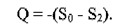
- the processor component 112 calculates a peak value Q p of the quadrature term Q.
- Q -( S 0 - S 2 )
- the processor component 112 calculates the peak value Q p :
- Q p M ⁇ 2 ⁇ B ⁇ sin M ⁇ sin ⁇
- the ratio R(M, ⁇ ) in one example describes a ratio of principal axes of an elliptical Lissajous pattern for an operating point.
- the operating point in one example comprises a value of the modulation depth M and a value of the demodulation phase offset ⁇ .
- the processor component 112 in one example calculates the values for the modulation depth M and the demodulation phase offset ⁇ such that the ratio R(M, ⁇ ) is substantially equal to one, to promote an increase in accuracy of a calculation of the phase angle ⁇ .
- the processor component 112 in one example employs the change in the phase angle ⁇ between multiple instances of the interference pulses 130, 132, and 134 to determine the change in the parameters employed by the sensors 124, 126, and 128.
- contour plots 202, 302, and 402 comprise a representation of the ratio R(M, ⁇ ) for a previous design, a first implementation of the apparatus of FIG. 1 , and a second implementation of the apparatus of FIG. 1 , respectively.
- the contour lines represent the ratio Q / I versus the modulation depth M and the demodulation phase offset ⁇ .
- Contour line 204, 304, and 404 represent values for the modulation depth M and the demodulation phase offset ⁇ where the value of R(M, ⁇ ) equals unity (100%).
- a modulation depth M is calculated to promote a decrease in sensitivity to the modulation depth M, as will be appreciated by those skilled in the art. For example, where a slope of the contour line 204, 304, and/or 404 approaches zero, the ratio R(M, ⁇ ) is least sensitive to the modulation depth M.
- An accuracy of the calculation of the phase angle ⁇ comprises a relationship with a maximum amplitude of the quadrature term Q and the in-phase term I.
- the ratio R(M, ⁇ ) is equal to unity, and the peak value Q p and the peak value I p are substantially equal.
- the contour plot 202 comprises a representation of the ratio R(M, ⁇ ) for a previous design that employs six samples.
- the contour line 204 comprises a value of "100%" for the ratio R(M, ⁇ ).
- the contour line 204 approaches zero at a modulation depth M of approximately 3.25 radians.
- a corresponding value of the demodulation phase offset ⁇ is 0.2914 radians.
- a common operating point for the previous design comprises a modulation depth M of 3.14 radians and a demodulation phase offset ⁇ of 0.2908.
- Four of the six samples are used to calculate Q, and four of the six samples are used to calculate I.
- the maximum amplitude for the quadrature term Q and the in-phase term I is equal to 4xB, where B is the interference term signal level.
- the contour line 304 comprises a value of "100%" for the ratio R(M, ⁇ ).
- the processor component 112 in one example calculates the modulation depth M approximately equal to 2.75 radians such that the slope of the contour line 304 approaches zero.
- the processor component 112 in a further example calculates a corresponding value of the demodulation phase offset ⁇ approximately equal to 0.5073 radians.
- I p is substantially equal to Q p .
- the contour line 404 comprises a value of "100%" for the ratio R(M, ⁇ ).
- the processor component 112 in one example calculates the modulation depth M approximately equal to 2.49 radians such that the slope of the contour line 404 approaches zero.
- the processor component 112 in a further example calculates a corresponding value of the demodulation phase offset ⁇ approximately equal to 0.3218 radians.
- I p is substantially equal to Q p .
- the modulation depth M of the respective operating point comprises a relationship with a drive voltage of the phase generated carrier.
- a lower drive voltage promotes a decrease in power consumption of the phase generated carrier, as will be appreciated by those skilled in the art.
- the modulation depth of the implementation of FIG. 3 is 88% of the modulation depth of the previous design of FIG. 2 .
- the modulation depth of the implementation of FIG. 4 is 79% of the modulation depth of the previous design of FIG. 2 .
- contour plots 502, 602, and 702 comprise exemplary representations of the contour plots 202, 302, and 402, respectively, with levels of total harmonic distortion.
- Contour lines 504, 604, and 704 comprise contour lines where R(M, ⁇ ) is equal to "99%.”
- Contour lines 506, 606, and 706 comprise contour lines where R(M, ⁇ ) is equal to "99.5%.”
- Contour lines 508, 608, and 708 comprise contour lines where R(M, ⁇ ) is equal to "100%.”
- Contour lines 510, 610, and 710 comprise contour lines where R(M, ⁇ ) is equal to "100.5%.”
- Contour lines 512, 612, and 712 comprise contour lines where R(M, ⁇ ) is equal to "101 %.”
- a tone with a peak-to-peak amplitude equal to ⁇ is used to evaluate the total harmonic distortion.
- ⁇ t / 2 ⁇ sin 2 ⁇ ⁇ ⁇ f tone ⁇ t + ⁇ + ⁇ dc
- f tone comprises a frequency of the tone
- ⁇ comprises a tone offset phase shift
- ⁇ dc comprises a non-alternating phase angle of the tone.
- the total harmonic distortion of the 2 nd through 10 th harmonics is evaluated at the operating point for the calculation of ⁇ of FIGS. 2-4 where the total harmonic distortion is at a minimum.
- contour plot 502 comprises a representation of the ratio R(M, ⁇ ) of FIG. 2 .
- the frequency f pgc is equal to 24.576 kHz and f tone is equal to 96 Hz. 4096 samples were taken over a period of 166.67 milliseconds.
- Values for total harmonic distortion for the contour lines 504, 506, 508, 510, and 512 comprise -49 dB, -54 dB, -59 dB, -54 dB, and -49 dB, respectively.
- contour plot 602 comprises a representation of the ratio R(M, ⁇ ) of FIG. 3 .
- the frequency f pgc is equal to 36.864 kHz and f tone is equal to 99 Hz. 4096 samples were taken over a period of 111.11 milliseconds.
- Values for total harmonic distortion for the contour lines 604, 606, 608, 610, and 612 comprise -49 dB, -53 dB, -57 dB, -53 dB, and -49 dB, respectively.
- contour plot 702 comprises a representation of the ratio R(M, ⁇ ) of FIG. 4 .
- the frequency f pgc is equal to 36.864 kHz and f tone is equal to 99 Hz. 4096 samples were taken over a period of 111.11 milliseconds.
- Values for total harmonic distortion for the contour lines 704, 706, 708, 710, and 712 comprise -49 dB, -53 dB, -56 dB, -53 dB, and -49 dB, respectively.
- the accuracy of the calculation of the phase angle ⁇ further comprises a relationship with a minimum horizontal shift in the modulation depth M and a minimum vertical shift in the demodulation phase offset ⁇ between the contour 100 and the contour 100.5.
- the calculation of FIG. 5 comprises a shift in modulation depth M of 0.095 radians and a shift in demodulation phase offset ⁇ of 0.0015 radians.
- the calculation of FIG. 6 comprises a shift in modulation depth M of 0.16 radians and a shift in demodulation phase offset ⁇ of 0.0013 radians.
- the calculation of FIG. 7 comprises a shift in modulation depth M of 0.16 radians and a shift in the demodulation phase offset ⁇ of 0.0013 radians.
- the accuracy of the calculation of the phase angle ⁇ for the previous design of FIGS. 2 and 5 and the exemplary implementations of FIGS. 3 , 4 , 6 , and 7 comprise a similar accuracy.
- the processor component 112 in one example employs only four samples as opposed to six samples to promote an increase in speed of calculation of the phase angle ⁇ . For example, the processor component 112 calculates the phase angle ⁇ 50% faster than the previous design.
- the increase in sampling rate allows for an increase in frequency f pgc of the phase generated carrier, as will be appreciated by those skilled in the art.
- the apparatus 100 in one example employs one or more computer-readable signal-bearing media.
- An exemplary computer-readable signal-bearing media for the apparatus 100 comprises the recordable data storage media 144 of the processor component 112.
- the computer-readable signal-bearing media for the apparatus 100 comprises one or more of a magnetic, electrical, optical, biological, and atomic data storage media.
- the computer-readable signal-bearing media comprises a modulated carrier signal transmitted over a network comprising or coupled with the apparatus 100, for instance, one or more of a telephone network, a local area network (“LAN”), the internet, and a wireless network.
- LAN local area network
Landscapes
- Physics & Mathematics (AREA)
- Engineering & Computer Science (AREA)
- Computer Networks & Wireless Communication (AREA)
- Signal Processing (AREA)
- General Physics & Mathematics (AREA)
- Electromagnetism (AREA)
- Optical Transform (AREA)
- Length Measuring Devices By Optical Means (AREA)
Claims (23)
- Procédé pour calculer un angle de phase variable dans le temps ϕ pour un réseau de capteurs (108) qui utilise un paramètre pour induire l'angle de phase variable dans le temps ϕ sur un signal optique qui comprend une porteuse générée par phase avec une période Tpgc, le procédé comprenant les étapes:d'échantillonnage d'un signal de sortie provenant du réseau de capteurs pour obtenir quatre échantillons pendant une période de temps Ts et à des intervalles de temps Ts/4, où Ts est égal à Tpgc ;de calcul d'un terme en phase 1 par l'utilisation d'un ou de plusieurs des quatre échantillons ;de calcul d'une valeur crête Ip du terme en phase I ;de calcul d'un terme en quadrature Q par l'utilisation d'un ou de plusieurs des quatre échantillons ;de calcul d'une valeur crête Qp du terme en quadrature Q ; etde calcul d'un point de fonctionnement qui comprend une profondeur de modulation M et un déphasage de démodulation β de la porteuse générée par phase par l'utilisation de la valeur crête Ip du terme en phase I et de la valeur crête Qp du terme en quadrature Q ;de calcul de l'angle de phase ϕ = arctangent(Q/I) au point de fonctionnement.
- Procédé selon la revendication 1, dans lequel les quatre échantillons comprennent des échantillons S0, S1, S2 et S3, dans lequel l'étape de calcul du terme en phase I par l'utilisation desdits un ou plusieurs des quatre échantillons comprend l'étape :de calcul du terme en phase 1 :

- Procédé selon la revendication 2, dans lequel l'étape de calcul de la valeur crête Ip du terme en phase I comprend l'étape :de calcul de la valeur crête Ip du terme en phase I :

- Procédé selon la revendication 3, dans lequel l'étape de calcul du terme en quadrature Q par l'utilisation desdits un ou plusieurs des quatre échantillons comprend l'étape :de calcul du terme en quadrature Q :

- Procédé selon la revendication 4, dans lequel l'étape de calcul de la valeur crête Qp du terme en quadrature Q comprend l'étape :de calcul de la valeur crête Qp du terme en quadrature Q :

- Procédé selon la revendication 3, dans lequel l'étape de calcul du terme en quadrature Q par l'utilisation desdits un ou plusieurs des quatre échantillons comprend l'étape :de calcul du terme en quadrature Q :

- Procédé selon la revendication 6, dans lequel l'étape de calcul de la valeur crête Qp du terme en quadrature Q comprend l'étape :de calcul de la valeur crête Qp :

- Appareil pour calculer un angle de phase variable dans le temps ϕ pour un réseau de capteurs (108) qui utilise un paramètre pour induire l'angle de phase variable dans le temps ϕ sur un signal optique qui comprend une porteuse générée par phase avec une période Tpgc, l'appareil comprenant :un composant de processeur (112) configuré pour échantillonner un signal de sortie du réseau de capteurs pour obtenir quatre échantillons pendant une période de temps Ts et à des intervalles de temps Ts/4, où Ts est égal à Tpgc ;dans lequel le composant de processeur est configuré pour calculer un terme en phase 1 par l'utilisation d'un ou de plusieurs des quatre échantillons ;dans lequel le composant de processeur est configuré pour calculer une valeur crête Ip du terme en phase I ;dans lequel le composant de processeur est configuré pour calculer un terme en quadrature Q par l'utilisation d'un ou de plusieurs des quatre échantillons ;dans lequel le composant de processeur est configuré pour calculer une valeur crête Qp du terme en quadrature Q ;dans lequel le composant de processeur est configuré pour calculer un point de fonctionnement qui comprend une profondeur de modulation M et un déphasage de démodulation β de la porteuse générée par phase par l'utilisation de la valeur crête Ip du terme en phase 1 et de la valeur crête Qp du terme en quadrature Q ; etdans lequel le composant de processeur est configuré pour calculer l'angle de phase ϕ = aretangent(Q/I) au point de fonctionnement.
- Appareil selon la revendication 8, dans lequel les quatre échantillons comprennent des échantillons S0, S1, S2 et S3 ;
dans lequel le composant de processeur est configuré pour calculer le terme en phase I :
et dans lequel le composant de processeur est configuré pour calculer le terme en quadrature Q :
- Appareil selon la revendication 9, dans lequel le composant de processeur est configuré pour calculer la valeur crête Ip :

et dans lequel le composant de processeur est configuré pour calculer la valeur crête Qp :
- Appareil selon la revendication 10, dans lequel le composant de processeur est configuré pour utiliser la valeur crête Ip et la valeur crête Qp pour calculer le point de fonctionnement qui comprend une profondeur de modulation M à peu près égale à 2,75 radians.
- Appareil selon la revendication 11, dans lequel le composant de processeur est configuré pour utiliser la valeur crête Ip et la valeur crête Qp pour calculer le point de fonctionnement qui comprend un déphasage de démodulation β à peu près égal à 0,5073 radian.
- Appareil selon la revendication 8, dans lequel les quatre seuls échantillons comprennent les échantillons S0, S1, S2 et S3 ;
dans lequel le composant de processeur est configuré pour calculer le terme en phase 1 :
et dans lequel le composant de processeur est configuré pour calculer le terme en quadrature Q :
- Appareil selon la revendication 13, dans lequel le composant de processeur est configuré pour calculer la valeur crête Ip :

et dans lequel le composant de processeur est configuré pour calculer la valeur crête Qp :
- Appareil selon la revendication 14, dans lequel le composant de processeur est configuré pour utiliser la valeur crête Ip et la valeur crête Qp pour calculer le point de fonctionnement qui comprend une profondeur de modulation M à peu près égale à 2,49 radians.
- Appareil selon la revendication 15, dans lequel le composant de processeur est configuré pour utiliser la valeur crête Ip et la valeur crête Qp pour calculer le point de fonctionnement qui comprend un déphasage de démodulation β à peu près égal à 0,3218 radian.
- Appareil selon la revendication 8, comprenant un ou plusieurs supports portant un signal pouvant être lus par un ordinateur (144) pour mémoriser les signaux échantillonnées.
- Appareil selon la revendication 17, dans lequel les quatre échantillons comprennent les échantillons S0, S1, S2 et S3, dans lequel le composant de processeur est configuré pour calculer le terme en phase 1 :

- Appareil selon la revendication 18, dans lequel le composant de processeur est configuré pour calculer la valeur crête Ip du terme en phase 1 :

- Appareil selon la revendication 19, dans lequel le composant de processeur est configuré pour calculez le terme en quadrature Q :
- Appareil selon la revendication 20, dans lequel le composant de processeur est configuré pour calculer la valeur crête Qp du terme en quadrature Q :

- Appareil selon la revendication 20, dans lequel le composant de processeur est configuré pour calculer le terme en quadrature Q :

- Appareil selon la revendication 22, dans lequel le composant de processeur est configuré pour calculer la valeur crête Qp :

Applications Claiming Priority (2)
| Application Number | Priority Date | Filing Date | Title |
|---|---|---|---|
| US10/615,730 US7012245B2 (en) | 2003-07-09 | 2003-07-09 | Calculation of sensor array induced phase angle |
| PCT/US2004/019466 WO2005010466A1 (fr) | 2003-07-09 | 2004-06-18 | Procede de calcul d'un signal de phase dans un reseau de capteurs a fibre optique comportant une onde porteuse generee par phase |
Publications (2)
| Publication Number | Publication Date |
|---|---|
| EP1642092A1 EP1642092A1 (fr) | 2006-04-05 |
| EP1642092B1 true EP1642092B1 (fr) | 2013-01-16 |
Family
ID=33564627
Family Applications (1)
| Application Number | Title | Priority Date | Filing Date |
|---|---|---|---|
| EP04776738A Expired - Lifetime EP1642092B1 (fr) | 2003-07-09 | 2004-06-18 | Procede de calcul d'un signal de phase dans un reseau de capteurs a fibre optique comportant une onde porteuse generee par phase |
Country Status (7)
| Country | Link |
|---|---|
| US (1) | US7012245B2 (fr) |
| EP (1) | EP1642092B1 (fr) |
| JP (1) | JP5053633B2 (fr) |
| KR (1) | KR101064298B1 (fr) |
| CA (1) | CA2534205A1 (fr) |
| NO (1) | NO20060635L (fr) |
| WO (1) | WO2005010466A1 (fr) |
Families Citing this family (5)
| Publication number | Priority date | Publication date | Assignee | Title |
|---|---|---|---|---|
| US7336365B2 (en) * | 2005-02-11 | 2008-02-26 | Optoplan As | Method and apparatus for suppression of crosstalk and noise in time-division multiplexed interferometric sensor systems |
| JP4844325B2 (ja) * | 2006-09-28 | 2011-12-28 | 沖電気工業株式会社 | 光ファイバセンサシステム |
| US20110194120A1 (en) * | 2009-05-21 | 2011-08-11 | Monash University | Method and device for phase measurement |
| CN111412936B (zh) * | 2020-03-10 | 2021-08-06 | 天津大学 | 一种全数字正交相移脉冲cotdr传感装置和方法 |
| CN114323092B (zh) * | 2021-12-28 | 2022-08-16 | 中国人民解放军国防科技大学 | 一种计算与消除内调制pgc信号检测中伴生调幅的方法 |
Family Cites Families (5)
| Publication number | Priority date | Publication date | Assignee | Title |
|---|---|---|---|---|
| US5903350A (en) | 1997-02-03 | 1999-05-11 | Optiphase, Inc. | Demodulator and method useful for multiplexed optical sensors |
| US6134281A (en) | 1998-02-10 | 2000-10-17 | Litton Systems, Inc. | Method and apparatus for calibration of a signal processing system utilizing digital down converters |
| US6154308A (en) * | 1998-07-30 | 2000-11-28 | Litton Systems, Inc. | Two step discrete phase shift demodulation method for fiber optic sensor arrays |
| US6122057A (en) * | 1999-07-30 | 2000-09-19 | Litton Systems, Inc. | Four step discrete phase shift demodulation method for fiber optic sensor arrays |
| US20060122057A1 (en) * | 2004-12-03 | 2006-06-08 | Ming-Theng Wang | Preparation of nanometered gold catalyzer |
-
2003
- 2003-07-09 US US10/615,730 patent/US7012245B2/en not_active Expired - Lifetime
-
2004
- 2004-06-18 WO PCT/US2004/019466 patent/WO2005010466A1/fr not_active Ceased
- 2004-06-18 EP EP04776738A patent/EP1642092B1/fr not_active Expired - Lifetime
- 2004-06-18 JP JP2006518655A patent/JP5053633B2/ja not_active Expired - Fee Related
- 2004-06-18 KR KR1020067000393A patent/KR101064298B1/ko not_active Expired - Fee Related
- 2004-06-18 CA CA002534205A patent/CA2534205A1/fr not_active Abandoned
-
2006
- 2006-02-09 NO NO20060635A patent/NO20060635L/no not_active Application Discontinuation
Also Published As
| Publication number | Publication date |
|---|---|
| JP5053633B2 (ja) | 2012-10-17 |
| US20050008278A1 (en) | 2005-01-13 |
| WO2005010466A1 (fr) | 2005-02-03 |
| CA2534205A1 (fr) | 2005-02-03 |
| KR101064298B1 (ko) | 2011-09-14 |
| KR20070017090A (ko) | 2007-02-08 |
| NO20060635L (no) | 2006-04-07 |
| JP2007527518A (ja) | 2007-09-27 |
| US7012245B2 (en) | 2006-03-14 |
| EP1642092A1 (fr) | 2006-04-05 |
Similar Documents
| Publication | Publication Date | Title |
|---|---|---|
| EP1915592B1 (fr) | Procede et appareil de detection directe de signaux provenant d'un systeme interferometrique d'heterodyne a retard differentiel | |
| EP2053364B1 (fr) | Mélange adaptatif pour vitesses de balayage élevées | |
| JP2021156822A (ja) | 光ファイバ振動検知装置及び振動検知方法 | |
| EP1639321B1 (fr) | Procede de calcul d'un signal de phase dans un reseau de capteurs a fibre optique comportant une onde porteuse generee par phase | |
| EP1068491B1 (fr) | Appareil et procede de suppression de bruit pour groupes de capteurs a fibres optiques a multiplexage par repartition dans le temps | |
| US6825714B2 (en) | Multichannel interferometer with phase generated carrier demodulation and quadrature error correction | |
| EP1072866A2 (fr) | Procédé de démodulation pour groupes de capteurs à fibres optiques | |
| US7012245B2 (en) | Calculation of sensor array induced phase angle | |
| EP1642091B1 (fr) | Calcul filtre de l'angle de phase provoque par un ensemble de capteurs, independant de l'angle de dephasage de la porteuse a phase generee | |
| AU2002252807A1 (en) | Multichannel interferometer with phase generated carrier demodulation and quadrature error correction | |
| EP0743507A3 (fr) | Gyroscope optique | |
| EP1651929B1 (fr) | Calcul d'angle de phase induit par un agencement de detection, fonde sur des signaux melanges | |
| KR19990077254A (ko) | 감지 방법 및 장치 | |
| KR20070017089A (ko) | 위상 생성 반송파의 복조 위상 오프셋과 독립적인 센서어레이 유도 위상각의 필터링된 계산 |
Legal Events
| Date | Code | Title | Description |
|---|---|---|---|
| PUAI | Public reference made under article 153(3) epc to a published international application that has entered the european phase |
Free format text: ORIGINAL CODE: 0009012 |
|
| 17P | Request for examination filed |
Effective date: 20051222 |
|
| AK | Designated contracting states |
Kind code of ref document: A1 Designated state(s): DE FR GB IT |
|
| 17Q | First examination report despatched |
Effective date: 20060808 |
|
| DAX | Request for extension of the european patent (deleted) | ||
| RBV | Designated contracting states (corrected) |
Designated state(s): DE FR GB IT |
|
| RAP1 | Party data changed (applicant data changed or rights of an application transferred) |
Owner name: NORTHROP GRUMMAN SYSTEMS CORPORATION |
|
| GRAJ | Information related to disapproval of communication of intention to grant by the applicant or resumption of examination proceedings by the epo deleted |
Free format text: ORIGINAL CODE: EPIDOSDIGR1 |
|
| GRAP | Despatch of communication of intention to grant a patent |
Free format text: ORIGINAL CODE: EPIDOSNIGR1 |
|
| GRAS | Grant fee paid |
Free format text: ORIGINAL CODE: EPIDOSNIGR3 |
|
| GRAA | (expected) grant |
Free format text: ORIGINAL CODE: 0009210 |
|
| RAP1 | Party data changed (applicant data changed or rights of an application transferred) |
Owner name: NORTHROP GRUMMAN GUIDANCE AND ELECTRONICS COMPANY, |
|
| AK | Designated contracting states |
Kind code of ref document: B1 Designated state(s): DE FR GB IT |
|
| REG | Reference to a national code |
Ref country code: GB Ref legal event code: FG4D |
|
| REG | Reference to a national code |
Ref country code: DE Ref legal event code: R096 Ref document number: 602004040805 Country of ref document: DE Effective date: 20130314 |
|
| PLBE | No opposition filed within time limit |
Free format text: ORIGINAL CODE: 0009261 |
|
| STAA | Information on the status of an ep patent application or granted ep patent |
Free format text: STATUS: NO OPPOSITION FILED WITHIN TIME LIMIT |
|
| 26N | No opposition filed |
Effective date: 20131017 |
|
| REG | Reference to a national code |
Ref country code: DE Ref legal event code: R097 Ref document number: 602004040805 Country of ref document: DE Effective date: 20131017 |
|
| PGFP | Annual fee paid to national office [announced via postgrant information from national office to epo] |
Ref country code: IT Payment date: 20140624 Year of fee payment: 11 |
|
| PG25 | Lapsed in a contracting state [announced via postgrant information from national office to epo] |
Ref country code: IT Free format text: LAPSE BECAUSE OF NON-PAYMENT OF DUE FEES Effective date: 20150618 |
|
| REG | Reference to a national code |
Ref country code: FR Ref legal event code: PLFP Year of fee payment: 13 |
|
| REG | Reference to a national code |
Ref country code: FR Ref legal event code: PLFP Year of fee payment: 14 |
|
| REG | Reference to a national code |
Ref country code: FR Ref legal event code: PLFP Year of fee payment: 15 |
|
| P01 | Opt-out of the competence of the unified patent court (upc) registered |
Effective date: 20230607 |
|
| PGFP | Annual fee paid to national office [announced via postgrant information from national office to epo] |
Ref country code: FR Payment date: 20230622 Year of fee payment: 20 Ref country code: DE Payment date: 20230620 Year of fee payment: 20 |
|
| PGFP | Annual fee paid to national office [announced via postgrant information from national office to epo] |
Ref country code: GB Payment date: 20230620 Year of fee payment: 20 |
|
| REG | Reference to a national code |
Ref country code: DE Ref legal event code: R071 Ref document number: 602004040805 Country of ref document: DE |
|
| PG25 | Lapsed in a contracting state [announced via postgrant information from national office to epo] |
Ref country code: GB Free format text: LAPSE BECAUSE OF EXPIRATION OF PROTECTION Effective date: 20240617 |
|
| PG25 | Lapsed in a contracting state [announced via postgrant information from national office to epo] |
Ref country code: GB Free format text: LAPSE BECAUSE OF EXPIRATION OF PROTECTION Effective date: 20240617 |