EP1642380B1 - Procede de commande d'un moteur electrique pourvu de plusieurs composants oscillants - Google Patents
Procede de commande d'un moteur electrique pourvu de plusieurs composants oscillants Download PDFInfo
- Publication number
- EP1642380B1 EP1642380B1 EP04736383A EP04736383A EP1642380B1 EP 1642380 B1 EP1642380 B1 EP 1642380B1 EP 04736383 A EP04736383 A EP 04736383A EP 04736383 A EP04736383 A EP 04736383A EP 1642380 B1 EP1642380 B1 EP 1642380B1
- Authority
- EP
- European Patent Office
- Prior art keywords
- coil
- oscillatory
- motor components
- electric signal
- electric
- Prior art date
- Legal status (The legal status is an assumption and is not a legal conclusion. Google has not performed a legal analysis and makes no representation as to the accuracy of the status listed.)
- Expired - Lifetime
Links
- 238000000034 method Methods 0.000 title claims abstract description 28
- 230000003534 oscillatory effect Effects 0.000 claims description 78
- 230000033001 locomotion Effects 0.000 claims description 46
- 230000010355 oscillation Effects 0.000 claims description 22
- 238000006073 displacement reaction Methods 0.000 abstract description 3
- 230000005284 excitation Effects 0.000 description 14
- XEEYBQQBJWHFJM-UHFFFAOYSA-N Iron Chemical group [Fe] XEEYBQQBJWHFJM-UHFFFAOYSA-N 0.000 description 7
- 238000010586 diagram Methods 0.000 description 6
- 230000000694 effects Effects 0.000 description 4
- CWYNVVGOOAEACU-UHFFFAOYSA-N Fe2+ Chemical compound [Fe+2] CWYNVVGOOAEACU-UHFFFAOYSA-N 0.000 description 3
- 239000000463 material Substances 0.000 description 3
- 230000001133 acceleration Effects 0.000 description 2
- 230000005540 biological transmission Effects 0.000 description 2
- 238000004140 cleaning Methods 0.000 description 1
- 230000008878 coupling Effects 0.000 description 1
- 238000010168 coupling process Methods 0.000 description 1
- 238000005859 coupling reaction Methods 0.000 description 1
- 230000001419 dependent effect Effects 0.000 description 1
- 230000007274 generation of a signal involved in cell-cell signaling Effects 0.000 description 1
- 230000006698 induction Effects 0.000 description 1
- 238000005259 measurement Methods 0.000 description 1
- 238000010008 shearing Methods 0.000 description 1
Images


Classifications
-
- H—ELECTRICITY
- H02—GENERATION; CONVERSION OR DISTRIBUTION OF ELECTRIC POWER
- H02K—DYNAMO-ELECTRIC MACHINES
- H02K33/00—Motors with reciprocating, oscillating or vibrating magnet, armature or coil system
- H02K33/12—Motors with reciprocating, oscillating or vibrating magnet, armature or coil system with armatures moving in alternate directions by alternate energisation of two coil systems
- H02K33/14—Motors with reciprocating, oscillating or vibrating magnet, armature or coil system with armatures moving in alternate directions by alternate energisation of two coil systems wherein the alternate energisation and de-energisation of the two coil systems are effected or controlled by movement of the armatures
-
- H—ELECTRICITY
- H02—GENERATION; CONVERSION OR DISTRIBUTION OF ELECTRIC POWER
- H02P—CONTROL OR REGULATION OF ELECTRIC MOTORS, ELECTRIC GENERATORS OR DYNAMO-ELECTRIC CONVERTERS; CONTROLLING TRANSFORMERS, REACTORS OR CHOKE COILS
- H02P25/00—Arrangements or methods for the control of AC motors characterised by the kind of AC motor or by structural details
- H02P25/02—Arrangements or methods for the control of AC motors characterised by the kind of AC motor or by structural details characterised by the kind of motor
- H02P25/032—Reciprocating, oscillating or vibrating motors
Definitions
- the invention relates to a method for controlling an electric motor having a plurality of oscillatory engine components for driving a small electrical appliance. Furthermore, the invention relates to a small electrical appliance with an electric motor having a plurality of oscillatory engine components.
- the linear motor has a stator coil and a plurality of rotor equipped with permanent magnets, which are offset by the stator coil in linear oscillatory movements.
- the deflections of the runners are detected by means of detectors associated with the runners and further processed in the form of an average value.
- the power supply of the stator coil is controlled as a function of the mean value so that the oscillation amplitudes of all runners are kept as constant as possible.
- the detectors each consist of a permanent magnet arranged on the respective rotor and a stationarily mounted sensor coil in which, by the action of the permanent magnet, an induction voltage dependent on the speed of the respective rotor is generated.
- the invention has for its object to drive a small electrical appliance in the best possible way.
- the oscillatory engine components are vibrated by a magnetic field generated by a coil in common for the oscillatory engine components.
- the peculiarity of the method according to the invention consists in the fact that the oscillatory movements of the oscillatory engine components are controlled individually by means of an electrical signal which is supplied to the coil.
- the invention has the advantage that a plurality of individually controllable drive movements can be provided with a comparatively low effort. All drive movements are generated by means of a common coil whose magnetic field acts on each equipped with an array of permanent magnets, oscillatory engine components and thereby drives them directly.
- the inventive method thus enables the realization of various drive functions with a single motor, which has a very simple mechanical and magnetic structure. A gear or other aids for influencing the drive movements are not required, so that the costs incurred thereby and the associated friction losses omitted. In addition, this results in the possibility of generating relatively high vibration frequencies.
- the electrical signal used in the method according to the invention is such that the magnetic field generated therefrom with the aid of the coil can in each case have a different effect on the individual oscillatory engine components. This means that because of the common coil, although the magnetic field always acts on all oscillatory engine components, the result of this action can be different for each oscillatory engine component.
- this individual influencing of the oscillatory movements of the individual oscillatory engine components by the magnetic field is achieved in that the oscillatory engine components are each components of vibration systems with different resonance frequencies. Since the effect of excitation on a vibratory system depends on its resonant frequency, the magnetic field typically develops a different effect for each oscillatory engine component. For this reason, it is possible, for example, to individually control the oscillatory movements of the oscillatory engine components via the specification of the frequency of the electrical signal supplied to the coil. Depending on how much this frequency deviates from the individual resonance frequencies, the Vibration movements of the oscillatory engine components differently influenced by the magnetic field generated by the signal.
- the electric signal supplied to the coil contains several different frequencies and the vibration movements of the oscillatory engine components are individually controlled by the weighting of the individual frequencies in the electrical signal. It is particularly advantageous if the individual frequencies correspond to the resonance frequencies of the vibration systems, which are formed with the oscillatory engine components. In this way, the oscillatory movements of the oscillatory engine components can be varied almost independently and within wide ranges.
- the electrical signal can be supplied to the coil in the form of pulses.
- the oscillatory movements of the oscillatory engine components can each be individually controlled via the specification of a pulse pattern for the electric signal supplied to the coil.
- the use of pulses has the advantage that the signal generation requires very little effort and the method can be used in particular also in small electrical appliances that do not have a network connection, but are operated with batteries or rechargeable batteries.
- the oscillation amplitudes of the oscillatory engine components can be controlled individually by means of the electrical signal supplied to the coil.
- the vibration amplitudes of the oscillatory engine components can be reduced to zero, so that the oscillatory engine components are individually switched on or off by means of the electric signal supplied to the coil.
- the characteristics of the actual vibration movements of the oscillatory engine components are detected individually by means of sensors for the oscillatory engine components.
- the amplitude and / or frequency and / or phase can serve as characteristics of the actual oscillatory movements of the oscillatory engine components.
- the characteristics can be used for the control of the oscillatory motions of the oscillatory engine components, that is, that the generation of the electric signal supplied to the coil is performed depending on the detected characteristics can be. It is particularly advantageous if the generation of the electrical signal supplied to the coil is carried out by means of a closed control loop. By doing so, a very precise control of the vibration movement can be achieved.
- the invention further relates to a small electrical appliance with an electric motor having a plurality of oscillatory engine components which are drivable by means of a common coil, and with a control device for outputting an electrical signal to the coil to at least temporarily a magnetic field for influencing the oscillatory motions of the oscillatory engine components to generate.
- the peculiarity of the small electric appliance is that with the control device, an electrical signal for the individual influencing of the vibration movements of the oscillatory engine components can be generated.
- one of the oscillatory engine components can be designed as a coil core for the coil.
- This oscillatory engine component thus assumes the function of a conventional stator, but without being arranged stationary.
- the coil core is arranged to be movable relative to the coil. This means that the coil can be arranged stationary and thus easier to contact than a movable coil.
- the oscillating mass is kept relatively low because the coil does not resonate.
- the electric motor is designed as an oscillating linear motor.
- Such a design of the electric motor is provided for example in an electric shaver.
- the electric motor is designed as an oscillating rotary motor. This may for example be the case with an electric toothbrush.
- Fig. 1 shows an embodiment of an oscillating linear motor in a schematic side view.
- the linear motor has a stationary arranged stator 1 and three rotor 2, which can each perform a linear oscillatory motion. Since the three runners 2 are arranged one behind the other, in the illustration of Fig. 1 only the foremost runner 2 visible.
- Fig. 2 shows the rotor 2 in a schematic plan view, so that in Fig. 2 all three runners 2 are visible.
- the oscillatory movements of the rotor 2 are in the Fig. 1 and 2 illustrated by a double arrow 3.
- the stator 1 consists of an iron core 4, which is in the form of a "U", and two legs 5, around each of which a part of a coil 6 is wound.
- the coil 6 is shown in section to release the view of the iron core 4.
- the two parts of the coil 6 are electrically connected to each other and can also be arranged spatially together, for example, by being wound around the crosspiece connecting the two legs 5 of the iron core 4.
- the runners 2 each have three permanent magnets 7, each of which abuts with one of its poles on a support plate 8 and arranged with antiparallel orientation close to each other are.
- the permanent magnets 7 are approximated to an air gap 9 the end faces of the legs 5 of the iron core 4.
- the support plates 8 are made as well as the iron core 4 made of a ferrous material and are connected on two opposite sides each with one end of a spring 10.
- the other ends of the springs 10 are fixedly suspended, for example, on a housing of a small electrical figurative device, not shown, in which the linear motor is installed, so that the rotor 2 can perform the designated by the double arrow 3 linear oscillatory movements.
- the coil 6 In the operating state of the linear motor, the coil 6, an electrical signal is supplied, so that a current flow is produced by the coil 6 and in the iron core 4, a magnetic field builds up.
- the magnetic field acts on the permanent magnets 7 and causes in the in Fig. 1 shown geometry a lateral displacement of the rotor 2 relative to the stator 1.
- the direction of the displacement depends on the current direction in the coil 6 from.
- the rotor 2 By means of a variation of the current flow through the coil 6, in which usually the current direction is varied, and supported by the springs 10, the rotor 2 can be set in linear oscillatory movements.
- the vibration behavior of the rotor 2 is in Fig. 3 shown.
- Fig. 3 shows a diagram for illustrating the vibration behavior of the in the Fig. 1 and 2 shown oscillating linear motor.
- the excitation frequency f is plotted on the abscissa and the amplitude A of the oscillatory motion is plotted on the ordinate, and a curve for the frequency behavior of the oscillation amplitude A is drawn for each of the three rotors 2.
- the three curves each have a similar course, which is characterized by a maximum oscillation amplitude A at the resonant frequency f1, f2 or f3 and a fall in the amplitude A with increasing distance from the resonant frequency f1, f2 or f3 to low and high excitation frequencies f characterized. Because of the different resonance frequencies f1, f2 and f3 of the three runners 2, the three curves are offset relative to each other.
- Fig. 3 is immediately apparent that it depends on the selected excitation frequency f in each case, how much the individual runners 2 are vibrated. For example, each of the rotor 2 is vibrated the strongest, the resonant frequency f1, f2 and f3 of the selected excitation frequency f is the next. The other two runners 2 reach with the same excitation only a lower oscillation amplitude A or may not be vibrated at all. For example, if the excitation frequency f lies exactly in the middle between the resonance frequencies f1 and f2 or f2 and f3 two rotor 2, these rotor 2 are excited to oscillations of the same amplitude A.
- the oscillation amplitudes A of the three runners 2 can be set individually. However, these oscillation amplitudes A can not be set arbitrarily by a single excitation frequency f, since only those combinations of oscillation amplitudes A of the three rotors 2 can be set, each of which can be set as intersections of the in Fig. 3 shown curves with a drawn at the excitation frequency f vertical line.
- any setting of the oscillation amplitudes A of the three sliders 2 within the limits prescribed by the system parameters is possible by using a plurality of excitation frequencies f.
- three excitation frequencies may be used which correspond to the three resonance frequencies f1, f2 and f3 of the rotor 2.
- the vibration amplitudes A thus achieved in the runners 2 depend on the amplitudes of the excitation signals.
- a slight influence on the respective other two runners 2 can additionally take place by means of each excitation signal.
- Fig. 4 shows a simplified block diagram illustrating the control principle according to the invention.
- the electrical signal required for driving the coil 6 of the stator 1 is generated by a microcontroller 11.
- the microcontroller 11 measurement data from three sensors 12 are supplied. With the sensors 12 respectively current values for the vibration amplitude, frequency and phase angle of the rotor 2 are detected.
- the microcontroller 11 compares these current values with preset reference values and controls the coil 6 in such a way that for each of the three runners 2 the deviations from the desired values are eliminated or at least reduced to a minimum.
- the microcontroller 11 generates three electrical vibration signals whose frequencies coincide with the resonance frequencies of the three rotor 2.
- the amplitudes of the electrical vibration signals each depend on the previously determined deviations of the actual values detected by the sensors 12 from the desired values.
- the electrical vibration signals are superimposed to form a sum signal, which is fed via a power amplifier 13 in the coil 6.
- the coil 6 thus receives an electrical signal with three frequency components, each of which may have different amplitudes and generates a corresponding magnetic field acting on the three runners 2.
- the three runners 2 are influenced differently and adjusted their vibration states in this way individually. The result achieved is monitored in each case with the sensors 12 and depending on the requirement is further intervened by a corresponding control of the coil 6 corrective.
- FIGS. 5, 6, and 7 show diagrams illustrating the individual control of two runners 2 of a linear motor.
- the time t is plotted on the abscissa and the velocity v of the rotor 2 or the voltage U of the signal generated by the microcontroller 11 is plotted on the ordinate.
- the first rotor 2 oscillates with high amplitude and low frequency.
- the associated time profile of the speed v is shown in each case as a solid line.
- the second rotor 2 oscillates with a significantly lower amplitude and three times the frequency of the first rotor 2.
- the time profile of the speed v of the second rotor 2 is shown as a dashed line.
- the signal generated by the microcontroller 11 consists of successive rectangular pulses. The rectangular pulses are easier to generate than, for example, sinusoidal signals.
- Fig. 5 a situation is shown in which positive Rckeckpulse each coincide with the maxima and negative Rckeckpulse each with the minima of the dashed curve shown.
- the electrical signal continuously causes an acceleration of the higher frequency oscillating rotor 2 and thus the vibration movement of this rotor 2 is amplified.
- the rectangular pulses partly the same and partly an opposite sign, so that the accelerating and decelerating effect of the electrical signal in the oscillating at lower frequency rotor 2 approximately canceled and the oscillatory motion of this rotor 2 by the electric Signal is thus not appreciably affected.
- Fig. 6 a situation is shown in which the square pulses each coincide with some of the zero crossings of the dashed curve and thus cancel the accelerating and decelerating portions of the electrical signal for the oscillating at higher frequency rotor 2 exactly.
- the positive Rckeckpulse respectively in the vicinity of the maxima and the negative rectangular pulses are each arranged in the vicinity of the minima. Consequently, results for the with the lower frequency oscillating rotor 2 by the electrical signal in each case an acceleration.
- the control method according to the invention can also be used to control an oscillating linear motor, which does not have a fixed stator 1, but via an additional rotor, which is constructive as the stator 1 is constructed, but is movable.
- an oscillating linear motor which does not have a fixed stator 1, but via an additional rotor, which is constructive as the stator 1 is constructed, but is movable.
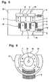
- Such a statorless, oscillating linear motor is in Fig. 8 shown.
- Fig. 8 shows an embodiment of a statorless, oscillating linear motor in a schematic side view.
- the active rotor 14 is constructive as the stator 1 of in Fig. 1 illustrated embodiment and used in an analogous manner to form a magnetic field, with the aid of the rotor 2 is driven.
- the peculiarity of the active rotor 14, however, is that it is not fixed in place in contrast to the stator 1, but is suspended by means of swinging bridges 15 movably on a housing 16 of the small electrical appliance.
- the swinging bridges 15 are leaf springs, which have a relatively small spring constant and thus form only a weak coupling to the housing 16.
- the active rotor 14 is connected via a spring 10 to the housing 16 in order to obtain a vibratory system.
- the rotor 2, which is identical to the in Fig. 1 illustrated embodiment is connected via swinging bridges 15 and a spring 10 to the housing 16. In this case, a single runner 2 or it can be provided a plurality of runners 2.
- Fig. 8 illustrated embodiment of the embodiment according to Fig. 1 in that the active rotor 14 is also set in a vibratory motion.
- the oscillatory motion of the active rotor 14 runs in antiphase to the oscillatory motion of the rotor 2.
- the individual control of the vibration movements meet those for the in Fig. 1 illustrated Embodiment of the linear motor with the stator 1 made information also for the present embodiment with the active rotor 14, wherein the active rotor 14 with respect to its oscillatory motion behaves like a conventional rotor 2.
- an oscillating linear motor can be used, for example, in an electric shaver.
- the in Fig. 8 illustrated embodiment can be used in a corresponding manner.
- the rotor 2 and the active rotor 14 are each connected to one of the two blades.
- the resonant frequencies of the two oscillatory systems ie, the two rotor 2 or the active rotor 14 and the rotor 2 and the respectively associated shear blade and the associated springs 10, slightly different choices.
- an electrical signal is generated which contains only one frequency, which lies between the two resonance frequencies.
- the two runners 2 and the rotor 2 and the active rotor 14 are driven so that they oscillate with the same frequency, the same amplitude and out of phase, so that only relatively small housing vibrations result.
- the magnet arrangements of the two rotor 2 are poled differently, to produce antiphase oscillations.
- a long-hair trimmer and possibly also a center cutter of the razor with the oscillating linear motor.
- a corresponding number of runners 2 are provided, which drive the respective components of the shaver.
- the electrical signal to drive the coil 6 is formed so that it additionally contains the resonance frequencies for the corresponding vibration systems, so that the runners 2, which drive the long-hair trimmer and the center cutter, can be selectively placed in a vibrational state.
- the cutting devices whose resonance frequencies are not included in the electrical signal, not driven, and are thus turned off.
- control method according to the invention can be applied not only to oscillating linear motors but also to oscillating rotary motors.
- Fig. 9 shows an embodiment of a statorless, oscillating rotary motor in a schematic side view.
- the statorless rotary motor has similar functional components as in Fig. 8 illustrated statorless linear motor. However, these functional components are each modified so that instead of an oscillating linear movement, an oscillating rotational movement arises.
- the statorless ration motor on an outer rotor 17 which is rotatably suspended and consists of a ferrous material.
- the outer rotor 17 extends partially within the coil 6 without touching, however, so that the outer rotor 17 can be rotated relative to the stationarily arranged coil 6.
- an inner rotor 18 is arranged, which has a rotor core 19 made of a ferrous material and permanent magnets 7 attached thereto.
- the inner rotor 18 is also rotatably suspended, wherein the outer rotor 17 and the inner rotor 18 have a common axis of rotation 20.
- the rotary motor still has a number of spring elements, which are arranged between the outer rotor 17 and the housing 16 and the inner rotor 18 and the housing 16 and for reasons of clarity in Fig. 9 are not shown.
- the rotary motor thus has two oscillatory systems. With regard to the control of the rotary motor, the above explanations apply to the control of the linear motor in an analogous manner.
- the rotary motor can be used for example as a drive for an electric toothbrush, wherein the in Fig. 9 illustrated embodiment of the rotary motor allows two different cleaning movements.
Landscapes
- Engineering & Computer Science (AREA)
- Power Engineering (AREA)
- Reciprocating, Oscillating Or Vibrating Motors (AREA)
- Apparatuses For Generation Of Mechanical Vibrations (AREA)
- Percussion Or Vibration Massage (AREA)
- Control Of Electric Motors In General (AREA)
Claims (20)
- Procédé pour commander un moteur électrique comprenant plusieurs composants de moteur oscillants (2, 14, 17, 18) destiné à entraîner un petit appareil électrique, les composants de moteur oscillants (2, 14, 17, 18) étant amenés en un mouvement oscillatoire par un champ magnétique qui est généré par une bobine (6) commune pour les composants de moteur oscillants (2, 14, 17, 18), caractérisé en ce que les mouvements oscillatoires des composants de moteur oscillants (2, 14, 17, 18) sont commandés individuellement au moyen d'un signal électrique qui est acheminé à la bobine (6).
- Procédé selon la revendication 1, caractérisé en ce que les composants de moteur oscillants (2, 14, 17, 18) sont respectivement les composants de systèmes oscillatoires ayant des fréquences de résonance différentes.
- Procédé selon l'une des revendications précédentes, caractérisé en ce que les mouvements oscillatoires des composants de moteur oscillants (2, 14, 17, 18) sont à chaque fois commandés individuellement en prédéfinissant la fréquence du signal électrique acheminé à la bobine (6).
- Procédé selon l'une des revendications 1 ou 2, caractérisé en ce que le signal électrique acheminé à la bobine (6) contient plusieurs fréquences différentes et les mouvements oscillatoires des composants de moteur oscillants (2, 14, 17, 18) sont à chaque fois commandés individuellement par la pondération des fréquences individuelles dans le signal électrique.
- Procédé selon la revendication 4, caractérisé en ce que les fréquences individuelles correspondent aux fréquences de résonance des systèmes oscillatoires qui sont réalisés avec les composants de moteur oscillants (2, 14, 17, 18).
- Procédé selon l'une des revendications précédentes, caractérisé en ce que le signal électrique est acheminé à la bobine (6) sous la forme d'impulsions.
- Procédé selon la revendication 6, caractérisé en ce que les mouvements oscillatoires des composants de moteur oscillants (2, 14, 17, 18) sont à chaque fois commandés individuellement en prédéfinissant un modèle d'impulsion pour le signal électrique acheminé à la bobine (6).
- Procédé selon l'une des revendications précédentes, caractérisé en ce que les amplitudes d'oscillation des composants de moteur oscillants (2, 14, 17, 18) sont commandées individuellement au moyen du signal électrique acheminé à la bobine (6).
- Procédé selon l'une des revendications précédentes, caractérisé en ce que les composants de moteur oscillants (2, 14, 17, 18) sont mis en service ou hors service individuellement au moyen du signal électrique acheminé à la bobine (6).
- Procédé selon l'une des revendications précédentes, caractérisé en ce que les grandeurs caractéristiques des mouvements oscillatoires réels des composants de moteur oscillants (2, 14, 17, 18) sont acquises individuellement pour les composants de moteur oscillants (2, 14, 17, 18) à l'aide de capteurs (12).
- Procédé selon la revendication 10, caractérisé en ce que les grandeurs caractéristiques utilisées des mouvements oscillatoires réels des composants de moteur oscillants (2, 14, 17, 18) sont respectivement l'amplitude et/ou la fréquence et/ou la phase.
- Procédé selon l'une des revendications 10 ou 11, caractérisé en ce que la génération du signal électrique acheminé à la bobine (6) est à chaque fois effectuée en fonction des grandeurs caractéristiques acquises.
- Procédé selon l'une des revendications 10 à 12, caractérisé en ce que la génération du signal électrique acheminé à la bobine (6) est effectuée au moyen d'un circuit de régulation fermé.
- Petit appareil électrique comprenant un moteur électrique qui présente plusieurs composants de moteur oscillants (2, 14, 17, 18) qui peuvent être entraînés au moyen d'une bobine (6) commune ainsi qu'un dispositif de commande (11) destiné à délivrer un signal électrique à la bobine (6) pour générer au moins temporairement un champ magnétique destiné à influencer les mouvements oscillatoires des composants de moteur oscillants (2, 14, 17, 18), caractérisé en ce qu'un signal électrique destiné à influencer individuellement les mouvements oscillatoires des composants de moteur oscillants (2, 14, 17, 18) peut être généré avec le dispositif de commande (11).
- Petit appareil électrique selon la revendication 14, caractérisé en ce que l'un des composants de moteur oscillants (14, 17) est réalisé sous la forme d'un noyau pour la bobine (6).
- Petit appareil électrique selon la revendication 15, caractérisé en ce que le composant de moteur oscillant (17) réalisé sous la forme d'un noyau de bobine est mobile par rapport à la bobine (6).
- Petit appareil électrique selon l'une des revendications 14 à 16, caractérisé en ce que le moteur électrique est réalisé sous la forme d'un moteur linéaire oscillant.
- Petit appareil électrique selon la revendication 17, caractérisé en ce qu'il est réalisé sous la forme d'un rasoir électrique.
- Petit appareil électrique selon l'une des revendications 14 à 16, caractérisé en ce que le moteur électrique est réalisé sous la forme d'un moteur rotatif oscillant.
- Petit appareil électrique selon la revendication 19, caractérisé en ce qu'il est réalisé sous la forme d'une brosse à dents électrique.
Applications Claiming Priority (2)
| Application Number | Priority Date | Filing Date | Title |
|---|---|---|---|
| DE10330979A DE10330979A1 (de) | 2003-07-09 | 2003-07-09 | Verfahren zur Steuerung eines Elektromotors mit mehreren schwingungsfähigen Motorkomponenten |
| PCT/EP2004/006198 WO2005006521A1 (fr) | 2003-07-09 | 2004-06-09 | Procede de commande d'un moteur electrique pourvu de plusieurs composants oscillants |
Publications (2)
| Publication Number | Publication Date |
|---|---|
| EP1642380A1 EP1642380A1 (fr) | 2006-04-05 |
| EP1642380B1 true EP1642380B1 (fr) | 2008-10-08 |
Family
ID=34041722
Family Applications (1)
| Application Number | Title | Priority Date | Filing Date |
|---|---|---|---|
| EP04736383A Expired - Lifetime EP1642380B1 (fr) | 2003-07-09 | 2004-06-09 | Procede de commande d'un moteur electrique pourvu de plusieurs composants oscillants |
Country Status (4)
| Country | Link |
|---|---|
| EP (1) | EP1642380B1 (fr) |
| AT (1) | ATE410813T1 (fr) |
| DE (2) | DE10330979A1 (fr) |
| WO (1) | WO2005006521A1 (fr) |
Families Citing this family (2)
| Publication number | Priority date | Publication date | Assignee | Title |
|---|---|---|---|---|
| DE102005045800A1 (de) * | 2005-09-24 | 2007-04-05 | Braun Gmbh | Elektrischer Rasierapparat |
| DE102023000282A1 (de) * | 2023-01-31 | 2024-08-01 | Edmund Pötsch | Pendelantriebs-Ansteuerungsvorrichtung und Pendelantriebs-Ansteuerungsverfahren |
Family Cites Families (7)
| Publication number | Priority date | Publication date | Assignee | Title |
|---|---|---|---|---|
| NL136196C (fr) * | 1960-09-29 | |||
| FR2179653B1 (fr) * | 1972-04-13 | 1974-07-26 | Crouzet Sa | |
| JP3382007B2 (ja) * | 1994-03-28 | 2003-03-04 | 松下電工株式会社 | 往復式電気かみそり |
| WO1995026261A1 (fr) * | 1994-03-28 | 1995-10-05 | Matsushita Electric Works, Ltd. | Rasoir a sec a mouvement alternatif |
| DE69937587T2 (de) * | 1998-04-23 | 2008-11-06 | Matsushita Electric Works, Ltd., Kadoma | Aktuator-Treiberschaltkreis |
| JP3791402B2 (ja) * | 2001-01-26 | 2006-06-28 | 松下電工株式会社 | リニア振動モータの駆動制御方法及び駆動制御装置 |
| US6548971B2 (en) * | 2001-05-22 | 2003-04-15 | Matsushita Electric Works, Ltd. | Dual sided self-oscillation circuit for driving an oscillatory actuator |
-
2003
- 2003-07-09 DE DE10330979A patent/DE10330979A1/de not_active Withdrawn
-
2004
- 2004-06-09 DE DE502004008215T patent/DE502004008215D1/de not_active Expired - Lifetime
- 2004-06-09 WO PCT/EP2004/006198 patent/WO2005006521A1/fr not_active Ceased
- 2004-06-09 AT AT04736383T patent/ATE410813T1/de active
- 2004-06-09 EP EP04736383A patent/EP1642380B1/fr not_active Expired - Lifetime
Also Published As
| Publication number | Publication date |
|---|---|
| ATE410813T1 (de) | 2008-10-15 |
| DE10330979A1 (de) | 2005-02-10 |
| EP1642380A1 (fr) | 2006-04-05 |
| DE502004008215D1 (de) | 2008-11-20 |
| WO2005006521A1 (fr) | 2005-01-20 |
Similar Documents
| Publication | Publication Date | Title |
|---|---|---|
| DE10330978A1 (de) | Elektrisches Kleingerät mit einem Elektromotor zur Erzeugung einer oszillierenden Bewegung | |
| DE19680506C2 (de) | Linearer Schwingungsantrieb | |
| EP1518318B1 (fr) | Procede pour commander un moteur electrique oscillant d'un petit appareil electrique | |
| EP1140439B1 (fr) | Dispositif de commande pour produits electriques oscillants d'usage individuel, en particulier rasoirs electriques | |
| EP1539437B1 (fr) | Petit electromenager comprenant un dispositif d'entrainement destine a produire un mouvement oscillatoire | |
| EP1108283B1 (fr) | Actionneur electromagnetique dote d'un systeme ressort-masse oscillant | |
| EP2220760B1 (fr) | Système à moteur oscillant et procédé de régulation d'un moteur oscillant | |
| EP1678813B1 (fr) | Unite d'entrainement pour produire un mouvement oscillant pour petits appareils electromenagers | |
| WO2005062445A1 (fr) | Moteur electrique pour petit appareil electrique | |
| EP2262084A1 (fr) | Moteur électrique pour un petit appareil électrique | |
| EP2262085A1 (fr) | Petit appareil électrique et unité d'entraînement électro-motorisée pour un petit appareil électrique | |
| EP1539439B1 (fr) | Petit electromenager comprenant un dispositif d'entrainement destine a produire un mouvement oscillatoire | |
| DE102005060537A1 (de) | Elektrischer Rasierapparat mit oszillierendem Scherkopf | |
| DE10242094A1 (de) | Antriebseinrichtung zum Erzeugen einer oszillierenden Bewegung für ein elektrisches Kleingerät | |
| EP0937328B1 (fr) | Mecanisme de reglage a moteur electrique | |
| EP1642380B1 (fr) | Procede de commande d'un moteur electrique pourvu de plusieurs composants oscillants | |
| DE60119648T2 (de) | Vorrichtung und Verfahren zum Antreiben bzw. Ansteuern eines Stellgliedes | |
| EP1539438B1 (fr) | Dispositif d'entrainement destine a produire un mouvement oscillatoire pour un petit electromenager | |
| EP3745584B1 (fr) | Système de récolte d'énergie cinétique à fréquence propre réglable | |
| DE10019226B4 (de) | Elektromechanischer Linearantrieb mit Momentenkompensation | |
| EP3300572B1 (fr) | Barre de coupe de moissonneuse | |
| DE2236297A1 (de) | Trockenrasierer | |
| WO2025190952A1 (fr) | Ensemble de coupe à commande magnétique pour machines électriques de coupe de cheveux/poils, machine électrique de coupe de cheveux/poils et procédé d'entraînement d'un tel ensemble de coupe |
Legal Events
| Date | Code | Title | Description |
|---|---|---|---|
| PUAI | Public reference made under article 153(3) epc to a published international application that has entered the european phase |
Free format text: ORIGINAL CODE: 0009012 |
|
| 17P | Request for examination filed |
Effective date: 20051201 |
|
| AK | Designated contracting states |
Kind code of ref document: A1 Designated state(s): AT BE BG CH CY CZ DE DK EE ES FI FR GB GR HU IE IT LI LU MC NL PL PT RO SE SI SK TR |
|
| DAX | Request for extension of the european patent (deleted) | ||
| 17Q | First examination report despatched |
Effective date: 20070313 |
|
| GRAP | Despatch of communication of intention to grant a patent |
Free format text: ORIGINAL CODE: EPIDOSNIGR1 |
|
| GRAS | Grant fee paid |
Free format text: ORIGINAL CODE: EPIDOSNIGR3 |
|
| GRAA | (expected) grant |
Free format text: ORIGINAL CODE: 0009210 |
|
| AK | Designated contracting states |
Kind code of ref document: B1 Designated state(s): AT BE BG CH CY CZ DE DK EE ES FI FR GB GR HU IE IT LI LU MC NL PL PT RO SE SI SK TR |
|
| REG | Reference to a national code |
Ref country code: GB Ref legal event code: FG4D Free format text: NOT ENGLISH |
|
| REG | Reference to a national code |
Ref country code: CH Ref legal event code: EP |
|
| REG | Reference to a national code |
Ref country code: IE Ref legal event code: FG4D Free format text: LANGUAGE OF EP DOCUMENT: GERMAN |
|
| REF | Corresponds to: |
Ref document number: 502004008215 Country of ref document: DE Date of ref document: 20081120 Kind code of ref document: P |
|
| PG25 | Lapsed in a contracting state [announced via postgrant information from national office to epo] |
Ref country code: SI Free format text: LAPSE BECAUSE OF FAILURE TO SUBMIT A TRANSLATION OF THE DESCRIPTION OR TO PAY THE FEE WITHIN THE PRESCRIBED TIME-LIMIT Effective date: 20081008 |
|
| NLV1 | Nl: lapsed or annulled due to failure to fulfill the requirements of art. 29p and 29m of the patents act | ||
| PG25 | Lapsed in a contracting state [announced via postgrant information from national office to epo] |
Ref country code: ES Free format text: LAPSE BECAUSE OF FAILURE TO SUBMIT A TRANSLATION OF THE DESCRIPTION OR TO PAY THE FEE WITHIN THE PRESCRIBED TIME-LIMIT Effective date: 20090119 Ref country code: BG Free format text: LAPSE BECAUSE OF FAILURE TO SUBMIT A TRANSLATION OF THE DESCRIPTION OR TO PAY THE FEE WITHIN THE PRESCRIBED TIME-LIMIT Effective date: 20090108 |
|
| PG25 | Lapsed in a contracting state [announced via postgrant information from national office to epo] |
Ref country code: NL Free format text: LAPSE BECAUSE OF FAILURE TO SUBMIT A TRANSLATION OF THE DESCRIPTION OR TO PAY THE FEE WITHIN THE PRESCRIBED TIME-LIMIT Effective date: 20081008 Ref country code: PL Free format text: LAPSE BECAUSE OF FAILURE TO SUBMIT A TRANSLATION OF THE DESCRIPTION OR TO PAY THE FEE WITHIN THE PRESCRIBED TIME-LIMIT Effective date: 20081008 Ref country code: FI Free format text: LAPSE BECAUSE OF FAILURE TO SUBMIT A TRANSLATION OF THE DESCRIPTION OR TO PAY THE FEE WITHIN THE PRESCRIBED TIME-LIMIT Effective date: 20081008 Ref country code: PT Free format text: LAPSE BECAUSE OF FAILURE TO SUBMIT A TRANSLATION OF THE DESCRIPTION OR TO PAY THE FEE WITHIN THE PRESCRIBED TIME-LIMIT Effective date: 20090218 |
|
| REG | Reference to a national code |
Ref country code: IE Ref legal event code: FD4D |
|
| PG25 | Lapsed in a contracting state [announced via postgrant information from national office to epo] |
Ref country code: RO Free format text: LAPSE BECAUSE OF FAILURE TO SUBMIT A TRANSLATION OF THE DESCRIPTION OR TO PAY THE FEE WITHIN THE PRESCRIBED TIME-LIMIT Effective date: 20081008 Ref country code: DK Free format text: LAPSE BECAUSE OF FAILURE TO SUBMIT A TRANSLATION OF THE DESCRIPTION OR TO PAY THE FEE WITHIN THE PRESCRIBED TIME-LIMIT Effective date: 20081008 Ref country code: EE Free format text: LAPSE BECAUSE OF FAILURE TO SUBMIT A TRANSLATION OF THE DESCRIPTION OR TO PAY THE FEE WITHIN THE PRESCRIBED TIME-LIMIT Effective date: 20081008 Ref country code: IE Free format text: LAPSE BECAUSE OF FAILURE TO SUBMIT A TRANSLATION OF THE DESCRIPTION OR TO PAY THE FEE WITHIN THE PRESCRIBED TIME-LIMIT Effective date: 20081008 |
|
| PLBE | No opposition filed within time limit |
Free format text: ORIGINAL CODE: 0009261 |
|
| STAA | Information on the status of an ep patent application or granted ep patent |
Free format text: STATUS: NO OPPOSITION FILED WITHIN TIME LIMIT |
|
| PG25 | Lapsed in a contracting state [announced via postgrant information from national office to epo] |
Ref country code: CZ Free format text: LAPSE BECAUSE OF FAILURE TO SUBMIT A TRANSLATION OF THE DESCRIPTION OR TO PAY THE FEE WITHIN THE PRESCRIBED TIME-LIMIT Effective date: 20081008 Ref country code: SE Free format text: LAPSE BECAUSE OF FAILURE TO SUBMIT A TRANSLATION OF THE DESCRIPTION OR TO PAY THE FEE WITHIN THE PRESCRIBED TIME-LIMIT Effective date: 20090108 |
|
| 26N | No opposition filed |
Effective date: 20090709 |
|
| PG25 | Lapsed in a contracting state [announced via postgrant information from national office to epo] |
Ref country code: SK Free format text: LAPSE BECAUSE OF FAILURE TO SUBMIT A TRANSLATION OF THE DESCRIPTION OR TO PAY THE FEE WITHIN THE PRESCRIBED TIME-LIMIT Effective date: 20081008 |
|
| BERE | Be: lapsed |
Owner name: BRAUN G.M.B.H. Effective date: 20090630 |
|
| PG25 | Lapsed in a contracting state [announced via postgrant information from national office to epo] |
Ref country code: MC Free format text: LAPSE BECAUSE OF NON-PAYMENT OF DUE FEES Effective date: 20090630 |
|
| REG | Reference to a national code |
Ref country code: CH Ref legal event code: PL |
|
| PG25 | Lapsed in a contracting state [announced via postgrant information from national office to epo] |
Ref country code: CH Free format text: LAPSE BECAUSE OF NON-PAYMENT OF DUE FEES Effective date: 20090630 Ref country code: LI Free format text: LAPSE BECAUSE OF NON-PAYMENT OF DUE FEES Effective date: 20090630 |
|
| PG25 | Lapsed in a contracting state [announced via postgrant information from national office to epo] |
Ref country code: BE Free format text: LAPSE BECAUSE OF NON-PAYMENT OF DUE FEES Effective date: 20090630 |
|
| PG25 | Lapsed in a contracting state [announced via postgrant information from national office to epo] |
Ref country code: GR Free format text: LAPSE BECAUSE OF FAILURE TO SUBMIT A TRANSLATION OF THE DESCRIPTION OR TO PAY THE FEE WITHIN THE PRESCRIBED TIME-LIMIT Effective date: 20090109 |
|
| PG25 | Lapsed in a contracting state [announced via postgrant information from national office to epo] |
Ref country code: LU Free format text: LAPSE BECAUSE OF NON-PAYMENT OF DUE FEES Effective date: 20090609 |
|
| PG25 | Lapsed in a contracting state [announced via postgrant information from national office to epo] |
Ref country code: HU Free format text: LAPSE BECAUSE OF FAILURE TO SUBMIT A TRANSLATION OF THE DESCRIPTION OR TO PAY THE FEE WITHIN THE PRESCRIBED TIME-LIMIT Effective date: 20090409 |
|
| PG25 | Lapsed in a contracting state [announced via postgrant information from national office to epo] |
Ref country code: TR Free format text: LAPSE BECAUSE OF FAILURE TO SUBMIT A TRANSLATION OF THE DESCRIPTION OR TO PAY THE FEE WITHIN THE PRESCRIBED TIME-LIMIT Effective date: 20081008 |
|
| PGFP | Annual fee paid to national office [announced via postgrant information from national office to epo] |
Ref country code: AT Payment date: 20110523 Year of fee payment: 8 |
|
| PG25 | Lapsed in a contracting state [announced via postgrant information from national office to epo] |
Ref country code: CY Free format text: LAPSE BECAUSE OF FAILURE TO SUBMIT A TRANSLATION OF THE DESCRIPTION OR TO PAY THE FEE WITHIN THE PRESCRIBED TIME-LIMIT Effective date: 20081008 |
|
| PGFP | Annual fee paid to national office [announced via postgrant information from national office to epo] |
Ref country code: IT Payment date: 20110614 Year of fee payment: 8 |
|
| REG | Reference to a national code |
Ref country code: AT Ref legal event code: MM01 Ref document number: 410813 Country of ref document: AT Kind code of ref document: T Effective date: 20120609 |
|
| PG25 | Lapsed in a contracting state [announced via postgrant information from national office to epo] |
Ref country code: IT Free format text: LAPSE BECAUSE OF NON-PAYMENT OF DUE FEES Effective date: 20120609 |
|
| PG25 | Lapsed in a contracting state [announced via postgrant information from national office to epo] |
Ref country code: AT Free format text: LAPSE BECAUSE OF NON-PAYMENT OF DUE FEES Effective date: 20120609 |
|
| REG | Reference to a national code |
Ref country code: FR Ref legal event code: PLFP Year of fee payment: 13 |
|
| REG | Reference to a national code |
Ref country code: FR Ref legal event code: PLFP Year of fee payment: 14 |
|
| PGFP | Annual fee paid to national office [announced via postgrant information from national office to epo] |
Ref country code: FR Payment date: 20170511 Year of fee payment: 14 Ref country code: GB Payment date: 20170607 Year of fee payment: 14 |
|
| PGFP | Annual fee paid to national office [announced via postgrant information from national office to epo] |
Ref country code: DE Payment date: 20180530 Year of fee payment: 15 |
|
| GBPC | Gb: european patent ceased through non-payment of renewal fee |
Effective date: 20180609 |
|
| PG25 | Lapsed in a contracting state [announced via postgrant information from national office to epo] |
Ref country code: FR Free format text: LAPSE BECAUSE OF NON-PAYMENT OF DUE FEES Effective date: 20180630 Ref country code: GB Free format text: LAPSE BECAUSE OF NON-PAYMENT OF DUE FEES Effective date: 20180609 |
|
| REG | Reference to a national code |
Ref country code: DE Ref legal event code: R119 Ref document number: 502004008215 Country of ref document: DE |
|
| PG25 | Lapsed in a contracting state [announced via postgrant information from national office to epo] |
Ref country code: DE Free format text: LAPSE BECAUSE OF NON-PAYMENT OF DUE FEES Effective date: 20200101 |