EP1642613A2 - Ventilsystem im Hochdruckbereich Hydrozephalus - Google Patents
Ventilsystem im Hochdruckbereich Hydrozephalus Download PDFInfo
- Publication number
- EP1642613A2 EP1642613A2 EP20050256120 EP05256120A EP1642613A2 EP 1642613 A2 EP1642613 A2 EP 1642613A2 EP 20050256120 EP20050256120 EP 20050256120 EP 05256120 A EP05256120 A EP 05256120A EP 1642613 A2 EP1642613 A2 EP 1642613A2
- Authority
- EP
- European Patent Office
- Prior art keywords
- valve
- threshold pressure
- aperture
- ball
- pressure
- Prior art date
- Legal status (The legal status is an assumption and is not a legal conclusion. Google has not performed a legal analysis and makes no representation as to the accuracy of the status listed.)
- Granted
Links
Images

Classifications
-
- A—HUMAN NECESSITIES
- A61—MEDICAL OR VETERINARY SCIENCE; HYGIENE
- A61M—DEVICES FOR INTRODUCING MEDIA INTO, OR ONTO, THE BODY; DEVICES FOR TRANSDUCING BODY MEDIA OR FOR TAKING MEDIA FROM THE BODY; DEVICES FOR PRODUCING OR ENDING SLEEP OR STUPOR
- A61M27/00—Drainage appliance for wounds or the like, i.e. wound drains, implanted drains
- A61M27/002—Implant devices for drainage of body fluids from one part of the body to another
- A61M27/006—Cerebrospinal drainage; Accessories therefor, e.g. valves
-
- Y—GENERAL TAGGING OF NEW TECHNOLOGICAL DEVELOPMENTS; GENERAL TAGGING OF CROSS-SECTIONAL TECHNOLOGIES SPANNING OVER SEVERAL SECTIONS OF THE IPC; TECHNICAL SUBJECTS COVERED BY FORMER USPC CROSS-REFERENCE ART COLLECTIONS [XRACs] AND DIGESTS
- Y10—TECHNICAL SUBJECTS COVERED BY FORMER USPC
- Y10T—TECHNICAL SUBJECTS COVERED BY FORMER US CLASSIFICATION
- Y10T137/00—Fluid handling
- Y10T137/0318—Processes
- Y10T137/0402—Cleaning, repairing, or assembling
- Y10T137/0491—Valve or valve element assembling, disassembling, or replacing
- Y10T137/0508—Ball valve or rotary ball valve
Definitions
- the present invention relates generally to medical devices for directing bodily fluids from one region of a patient to another region, and in particular the invention relates to an adjustable implantable valve for treating hydrocephalus.
- Hydrocephalus is a condition afflicting patients who are unable to regulate cerebrospinal fluid flow through their body's own natural pathways.
- CSF cerebrospinal fluid
- the cerebrospinal fluid is normally absorbed by the body's venous system.
- the cerebrospinal fluid is not absorbed in this manner, but instead accumulates in the ventricles of the patient's brain. If left untreated, the increasing volume of fluid elevates the patient's intracranial pressure and can lead to serious medical conditions such as compression of the brain tissue and impaired blood flow to the brain.
- a drainage system commonly referred to as a shunt
- a shunt is often used to carry out the transfer of fluid.
- a scalp incision is made and a small hole is drilled in the skull.
- a proximal, or ventricular, catheter is installed in the ventricular cavity of the patient's brain, while a distal, or drainage, catheter is installed in that portion of the patient's body where the excess fluid is to be reintroduced.
- a pump or one-way control valve can be placed between the proximal and distal catheters.
- the shunt systems include a valve mechanism that operates to permit fluid flow only once the fluid pressure reaches a certain threshold level. That is, fluid enters the valve only when the fluid pressure overcomes the valve mechanism's resistance to open.
- Some valve mechanisms permit the adjustment, or programming, of the opening pressure level, or resistance level, at which fluid flow commences.
- These valve mechanisms can comprise a variety of configurations.
- the valve mechanism can be configured as a ball-in-cone as illustrated and described in U.S. Patent Nos. 3,886,948, 4,332,255, 4,387,715, 4,551,128, 4,595,390, 4,615,691, 4,772,257, and 5,928,182, all of which are hereby incorporated by reference.
- valve device that can be used to gradually increase the threshold pressure, preferably in relatively small and precise increments, thereby forcing the patient's own physiologic resorption system to compensate and eventually become shunt independent.
- a valve for use in treating hydrocephalus generally includes a housing having an inlet and an outlet, a valve element disposed within the housing and effective to allow fluid to flow from the inlet in the housing to the outlet in the housing when a fluid pressure at the inlet is greater than a threshold pressure of the valve element, and an adjustment mechanism that is coupled to the valve element and that is effective to selectively adjust the threshold pressure up to at least about 400 mm H 2 O at increments in the range of about 10 mm H 2 O to 40 mm H 2 O.
- the threshold pressure is adjustable in substantially uniform increments, and more preferably in increments of about 20 mm H 2 O.
- valve element can have a variety of configurations and virtually any valve mechanism know in the art can be used in accordance with the present invention.
- the valve is preferably, however, configured to remain closed until a fluid pressure differential between the inlet of the valve and the outlet of the valve exceeds a certain selected valve opening pressure.
- suitable valve elements include a tapered pin and aperture, a sliding shutter, a shutter/gate mechanism, and a ball-in-cone construct.
- the valve element includes an aperture, a restricting element, such as a ball, disposed within the aperture and having a width or diameter greater than a width or diameter of the aperture, and a biasing member coupled to an adjustment mechanism and effective to bias the restricting element against the aperture at the threshold pressure.
- the biasing member can be, for example, a spring extending between the adjustment mechanism and the ball, and the adjustment mechanism can be, for example, a cam mechanism having a plurality of positions formed thereon with each position corresponding to a predetermined threshold pressure.
- each position can be in the form of a step, and the cam can include 18 steps formed thereon.
- At least a portion of the aperture in the valve can be in the shape of a cone having a cone angle of at least about 70°, and more preferably about 95°, and the ball can have a diameter of at least about 0.8 mm, and more preferably about 1.2 mm.
- the aperture includes a proximal cone-shaped portion adapted to seat the ball and having a chamfer formed along an edge thereof, and a distal substantially cylindrical portion.
- the distal substantially cylindrical portion preferably has a maximum diameter of about 0.8 mm.
- a valve for use in treating hydrocephalus includes an inlet and an outlet and a valve element in communication with the inlet and outlet and effective to allow fluid to flow from the inlet to the outlet when a fluid pressure at the inlet is greater than a threshold pressure of the valve element.
- the threshold pressure is preferably selectively adjustable up to a pressure of at least about 400 mm H 2 O at increments of about 20 mm H 2 O.
- the valve element includes an aperture, a ball disposed within the aperture and having a diameter greater than a diameter of the aperture, and a biasing member effective to bias the ball against the aperture at the threshold pressure.
- the valve element can also include an adjustment mechanism that is coupled to the biasing member and that is effective to selectively adjust the threshold pressure.
- the biasing member can be, for example, a spring extending between the cam and the ball, and the adjustment mechanism can be, for example, a cam mechanism having a plurality of steps formed thereon, each step corresponding to a threshold pressure.
- the present invention also provides a method for treating hydrocephalus.
- the method includes the steps of implanting a valve in a patient's body such that fluid in the patient's body can flow into an inlet in the valve and out through an outlet in the valve, and periodically and repeatedly increasing a threshold pressure of the valve up to at least about 400 mm H 2 O at increments in the range of about 10 mm H 2 O to 40 mm H 2 O such that fluid can only flow through the valve when a fluid pressure at the inlet is greater than the threshold pressure of the valve element.
- the threshold pressure of the valve is increased from an initial pressure in the range of about 30 mm H 2 O to 200, and more preferably from about 30 mm H 2 O to 140 mm H 2 O to a final pressure in the range of about 200 mm H 2 O to 500 mm H 2 O, and more preferably from about 300 mm H 2 O to 400 mm H 2 O.
- the threshold pressure of the valve is increased in increments of about 5% of the total valve operating pressure range.
- a method for treating hydrocephalus includes the step of implanting a shunt system having a proximal catheter disposed within a ventricular cavity of the patient's brain, a distal catheter installed at a remote location in the patient's body where fluid is to be reintroduced, and a valve disposed between the proximal and distal catheters and adapted to control a rate of fluid flow from the ventricular cavity to the remote location.
- a threshold pressure of the valve is then set such that fluid can only flow through the valve when a fluid pressure in the first catheter is greater than the threshold pressure of the valve.
- the threshold pressure is then periodically increased at increments in the range of about 10 mm H 2 O to 40 mm H 2 O until a pressure greater than about 400 mm H 2 O is achieved such that the shunt system can be removed and the patient is cured of hydrocephalus.
- FIG. 1 is partially cross-sectional side view of a prior art hydrocephalus shunt system implanted within a ventricle of a patient's brain;
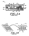
- FIG. 2A is a side, sectional view of a prior art externally programmable shunt valve
- FIG. 2B is perspective view of a prior art programmer for programming the prior art shunt valve of FIG. 2A;
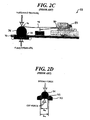
- FIG. 2C is a side view illustration of the valve element of the externally programmable shunt valve shown in FIG. 2A;
- FIG. 2D is a cross-sectional side view illustration of the ball-in-cone portion of the externally programmable shunt valve shown in FIG. 2A;
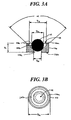
- FIG. 3A is a cross-sectional side view illustration of one embodiment of support plate having a ball-in-cone valve element in accordance with the present invention for use in a hydrocephalus valve;
- FIG. 3B is a top view of the support plate shown in FIG. 3A.
- the present invention generally provides a valve for use in a shunt system to drain fluid from one part of a patient's body to another. While the valve is primarily described in connection with a shunt system for treating hydrocephalus, the valve can be used in other types of implantable devices for controlling fluid flow.
- the valve is operable at a threshold pressure that is selectively adjustable up to at least about 400 mm H 2 O at increments in the range of about 10 mm H 2 O to 40 mm H 2 O. The ability of the valve to operate at a high threshold pressure and to be adjusted at relatively small and precise increments renders the valve particularly advantageous for use in younger hydrocephalus patients.
- the threshold pressure of the valve can be gradually increased in small increments over a period of time to reduce the amount of fluid flowing through the valve and slowly force the patient's own resorption system to circulate cerebrospinal fluid and.
- shunt independence can be achieved thereby allowing the shunt to be successfully removed.
- FIG. 1 illustrates a prior art shunt system 10.
- the system 10 generally includes a proximal catheter 12, also referred to as a ventricular catheter, that is disposed within a ventricular cavity 18 of the patient's brain, a distal catheter 14, also referred to as a drainage catheter, that is installed at a remote location, e.g., the circulatory system, in the patient's body where fluid is to be reintroduced, and a valve 16 that is disposed between the proximal and distal catheters 12, 14 and that is adapted to control a rate of fluid flow from the ventricular cavity 16 to the remote location.
- the system 10 also includes an external programming device (not shown) for adjusting a threshold pressure at which fluid can flow from the proximal catheter 12 through the valve 16 to the distal catheter 14 to be delivered at the remote location.
- FIGS. 2A-2D illustrate one embodiment of a prior art externally programmable valve system 50 and an external programming device 52 for adjusting a threshold pressure at which fluid begins to flow through the device.
- the valve 50 and external programming device 52 are described in more detail in U.S. Patent Nos. 3,886,948, 4,332,255, 4,387,715, 4,551,128, 4,595,390, 4,615,691, 4,772,257, and 5,928,182, all of which are hereby incorporated by reference.
- the shunt valve 50 generally includes a valve body 60 defining a chamber 62 with an inlet 64 and an outlet 66.
- a support plate 68 is disposed within the valve body 60 and it separates the inlet 64 from the outlet 66.
- An aperture 70 is formed in the support plate 68 at one end thereof and it defines a valve seat 72 for seating a ball 74 in sealing engagement therewith.
- the valve seat 72 is substantially cone-shaped and it has a cone angle of about 60°.
- the ball 74 and the aperture 70 can be formed from a polished hard material, preferably a ruby or synthetic sapphire, to ensure an effective seal when the ball 74 is seated in the valve seat 72, and to lessen the tendency for the ball 74 to become stuck in the seat 72.
- the spherical ball 74 has a diameter d b that is larger than the diameter d a of the aperture 70, but that is substantially the same as a radius of curvature of the valve seat 72.
- the spherical ball has a diameter d b that is about 1.57 mm (0.062 inches), which is substantially the same as the radius of curvature of the valve seat 72, but which is greater than the diameter d a of the aperture 70, which is about 1.45 mm (0.053 inches).
- the valve 50 also includes a biasing element, e.g., spring 78, having a first end 76 that biases the ball 74 into the valve seat 72 to prevent fluid flow through the aperture 70, and thus through the valve 50.
- the second end 80 of the spring 78 is coupled to a cam mechanism 82 that is effective to change the biasing force of the spring 78 against the ball 74.
- the cam mechanism 82 includes a circular staircase of eighteen steps 83, each being grooved so as to have a V-shape cross section.
- the end 80 of the spring 78 that is position on the steps 83 also has a similar V-shape chosen to mate with the V-shape of steps 83.
- a barrier (not shown) is provided at each end of the staircase 83 .
- the V-shape of steps 83 act as detents to keep the cam 82 in precisely one of eighteen possible angular positions. That means that the vertical position of free end 80 of the spring 78 is always at precisely one of eighteen different values.
- the cam 82 is rotated to increase or decrease a height of the spring 78 at a second end 80, thereby increasing or decreasing the pressure applied to the ball 74 by the first end 76 of the spring 78.
- the biasing force provided by the spring 78 therefore determines the threshold pressure that must be overcome in order to separate the ball 74 from the valve seat 72 to allow fluid flow into the chamber 62 and out the outlet 66 of the valve 50.
- the cam 82 is disposed in a centrally located hole in a rotor 84 which includes a plurality of permanent magnetic poles of alternate polarity. At any one angular position, a pole exposed on the top side has an opposite pole on the other side.
- a stator member 86 below the rotor 84, four stator elements are fixed in a stator member 86.
- the stator elements are formed from a magnetically soft and permeable material. The stator elements are shaped to conform to the rotor 84 elements.
- the shunt valve 50 is surgically implanted under the scalp of a patient and it is coupled to proximal and distal catheters, as shown in FIG. 1.
- a threshold pressure of the valve 50 can be adjusted by using the programmer 52 shown in FIG. 2B.
- the programmer 52 includes a control device 54 for selecting a threshold pressure and a programming element 56 that is configured to be placed over the valve.
- the programming element 56 includes a housing 90 with a groove 92 that is adapted to conform to a protrusion on the scalp caused by the implanted shunt valve 50.
- an operator maneuvers the programming element 56 so that the scalp protrusion is within the groove 92.
- a series of electromagnets 94 disposed about a central axis are sequentially energized to apply a pulsed magnetic field to the stepper motor and cause the rotor 84 to rotate.
- This causes the cam 82 to rotate to one of eighteen positions, therefore adjusting the pressure applied to the ball 74 by the first end 76 of the spring 78.
- the threshold pressure of the shunt valve 50 is adjusted. Due to the size of the aperture 70, the size of the ball 74, and the number of steps 83 on the cam 82, the valve 50 can be adjusted in increments of 10 mm H 2 O to one of eighteen pressures ranging from 20 mm H 2 O to 190 mm H 2 O.
- FIGS. 3A and 3B illustrate a portion of a shunt valve in accordance with the present invention.
- the valve is configured to allow the threshold pressure to be adjusted up to a threshold pressure of at least about 400 mm H 2 O, and more preferably about 500 mm H 2 O.
- the threshold pressure is also preferably adjustable in increments ranging from 10 mm H 2 O to 40 mm H 2 O, and more preferably in increments of about 20 mm H 2 O.
- a support plate 116 similar to support plate 68 of valve 50.
- the support plate 116 can vary in shape and size, but in an exemplary embodiment, as shown, the support plate 116 has a substantially cylindrical shape with a diameter D s that is preferably in the range of about 1.5 mm to 3.0 mm, and more preferably that is about 2.2 mm, and a height H s that is in the range of about 0.7 mm to 1.5 mm, and more preferably that is about 0.9 mm.
- the support plate 116 includes an aperture 114 formed therein for seating a ball 112.
- the aperture 114 includes a proximal portion or chamfer 114a, a cone-shaped or mid-portion 114b which defines the valve seat for seating the ball 112, and a distal, substantially cylindrical portion 114c.
- the chamfer 114a is substantially cylindrical such that the sidewalls extend parallel to one another, and it extends from the mid-portion 114b to a proximal surface 116a of the support plate 68.
- the chamfer 114a is particularly advantageous in that it provides performance characteristics, such as flow regulation and anti-reflux, while preventing the ball from becoming unseated during normal valve operations (i.e. physiologic flow conditions).
- the size of the aperture 114 and ball 112 can vary, but in an exemplary embodiment, the proximal portion has a diameter Dp that is in the range of about 1.6 mm (0.063 inches) to 1.8 mm (0.071 inches), and more preferably that is about 1.7 mm (0.067 inches), and the distal portion 114c has a diameter D d that is substantially smaller than the diameter Dp of the proximal portion 114a. In an exemplary embodiment, the distal portion 114c has a diameter D d that is in the range of about 0.70 mm (0.027 inches) to 0.80 mm (0.031 inches), and more preferably that is about 0.762 mm (0.030 inches).
- the ball 112 has a diameter D b that is less than the diameter Dp of the proximal portion 114a, but that is greater than the diameter D d of the distal portion 114c.
- the ball 112 has a diameter D b that is greater than 0.8 mm (0.031 inches), and more preferably that is about 1.2 mm (0.047 inches).
- the mid-portion 114b has sidewalls that extend at an angle a relative to one another, and in an exemplary embodiment, the cone angle a between the sidewalls is greater than about 70°, and more preferably it is about 95°.
- the ball 112 will not extend through the distal portion 114c and beyond a distal surface 116b of the support plate 116, but rather it will rest substantially within the mid-portion 114b to seal the aperture 114.
- the ball 112 and aperture 114 can be used in a variety of programmable valves, but in an exemplary embodiment they are used with a valve similar to valve 50 shown in FIGS. 2A, 2C, and 2D.
- rotation of the cam 82 to one of the eighteen steps 83 will be effective to adjust the pressure up to a threshold pressure of at least about 400 mm H 2 O, and more preferably about 500 mm H 2 O.
- each step 83 on the cam 82 will change the pressure in increments of 20 mm H 2 O.
- the incremental changes in the threshold pressure can, however, vary depending on the size of the ball 112 and aperture 114, as well as the height of the steps 83.
- the threshold pressure can be adjusted in increments of about 5% of the total valve operating pressure range, or in increments of about 10 mm H 2 O to 40 mm H 2 O up to a pressure of at least about 400 mm H 2 O, and more preferably about 500 mm H 2 O.
- the ability of the valve to operate at a high threshold pressure of about 200 mm H 2 O to 500 mm H 2 O can be used to achieve shunt independence.
- the procedure begins by first setting the threshold pressure of the valve to a desired level according to the circumstances of the case, and then surgically implanting the valve in a patient following well-known procedures. Further adjustments in pressure can be made at subsequent times, as necessary.
- the threshold pressure is then periodically (e.g., 1 month after initial operation to 2-3 years) increased in small increments (e.g., 10 mm H 2 O to 40 mm H 2 O) to force the patient's own resorption system to circulate the CSF.
- valve Once a pressure of about 400 mm H 2 O or greater is achieved, the valve is substantially in an off position, indicating that the patient's own resorption system is circulating cerebrospinal fluid. Shunt independent is therefore achieved, thus allowing the shunt to be successfully removed.
- valve element can have a variety of configurations and virtually any valve mechanism know in the art can be used in accordance with the present invention.
- the valve is preferably, however, configured to remain closed until a fluid pressure differential between the inlet of the valve and the outlet of the valve exceeds a certain selected valve opening pressure.
- suitable valve elements include a tapered pin and aperture, a sliding shutter, a shutter/gate mechanism, and a ball-in-cone construct.
Landscapes
- Health & Medical Sciences (AREA)
- Engineering & Computer Science (AREA)
- Biomedical Technology (AREA)
- Neurology (AREA)
- Ophthalmology & Optometry (AREA)
- Otolaryngology (AREA)
- Anesthesiology (AREA)
- Heart & Thoracic Surgery (AREA)
- Hematology (AREA)
- Life Sciences & Earth Sciences (AREA)
- Animal Behavior & Ethology (AREA)
- General Health & Medical Sciences (AREA)
- Public Health (AREA)
- Veterinary Medicine (AREA)
- External Artificial Organs (AREA)
- Details Of Valves (AREA)
- Lubricants (AREA)
Applications Claiming Priority (1)
| Application Number | Priority Date | Filing Date | Title |
|---|---|---|---|
| US10/955,258 US7559912B2 (en) | 2004-09-30 | 2004-09-30 | High pressure range hydrocephalus valve system |
Publications (3)
| Publication Number | Publication Date |
|---|---|
| EP1642613A2 true EP1642613A2 (de) | 2006-04-05 |
| EP1642613A3 EP1642613A3 (de) | 2006-05-31 |
| EP1642613B1 EP1642613B1 (de) | 2010-05-19 |
Family
ID=35478644
Family Applications (1)
| Application Number | Title | Priority Date | Filing Date |
|---|---|---|---|
| EP20050256120 Expired - Lifetime EP1642613B1 (de) | 2004-09-30 | 2005-09-29 | Hochdruckbereichs Hydrozephalus Ventilsystem |
Country Status (9)
| Country | Link |
|---|---|
| US (2) | US7559912B2 (de) |
| EP (1) | EP1642613B1 (de) |
| JP (1) | JP4689424B2 (de) |
| AT (1) | ATE468146T1 (de) |
| AU (1) | AU2005209679B2 (de) |
| BR (1) | BRPI0504578B8 (de) |
| CA (1) | CA2521696C (de) |
| CO (1) | CO5700177A1 (de) |
| DE (1) | DE602005021289D1 (de) |
Cited By (4)
| Publication number | Priority date | Publication date | Assignee | Title |
|---|---|---|---|---|
| EP2366423A3 (de) * | 2009-12-30 | 2012-05-16 | Codman Neuro Sciences Sarl | Elektrokinetischer Aktuator zur Flüssigkeitsstromtitrierung |
| WO2012065750A2 (de) | 2010-11-19 | 2012-05-24 | C.Miethke Gmbh & Co Kg | Elektrisch betätigbares, insbesondere programmierbares hydrocephalus-ventil |
| US9572965B2 (en) | 2012-09-11 | 2017-02-21 | C.Miethke Gmbh & Co Kg | Adjustable hydrocephalus valve |
| US10569065B2 (en) | 2012-09-11 | 2020-02-25 | Christoph Miethke Gmbh & Co Kg | Adjustable hydrocephalus valve |
Families Citing this family (15)
| Publication number | Priority date | Publication date | Assignee | Title |
|---|---|---|---|---|
| US20030216710A1 (en) * | 2002-03-26 | 2003-11-20 | Hurt Robert F. | Catheter |
| US9694166B2 (en) | 2002-03-26 | 2017-07-04 | Medtronics Ps Medical, Inc. | Method of draining cerebrospinal fluid |
| US8002730B2 (en) * | 2005-04-29 | 2011-08-23 | Medtronic, Inc. | Anti-thrombogenic venous shunt system and method |
| US7334594B2 (en) * | 2005-06-29 | 2008-02-26 | Codman & Shurtleff, Inc. | Apparatus and method for adjusting a locking mechanism of a shunt valve |
| DE112009005095B4 (de) * | 2008-12-11 | 2014-05-22 | Fraunhofer-Gesellschaft zur Förderung der angewandten Forschung e.V. | Implantierbares Kraftübertragungssystem, insbesondere zur Einstellung eines Ventils |
| DE102008061639A1 (de) | 2008-12-11 | 2010-07-15 | Fraunhofer-Gesellschaft zur Förderung der angewandten Forschung e.V. | Implantierbares Kraftübertragungssystem, insbesondere zur Einstellung eines Ventils |
| DE102009060533B4 (de) * | 2009-12-23 | 2019-07-11 | Christoph Miethke Gmbh & Co Kg | Implantierbares Shuntsystem |
| JP5844359B2 (ja) * | 2010-06-29 | 2016-01-13 | リサーチ メディカル プロプライエタリー リミテッドResearch Medical Pty Ltd | 創傷ドレナージ制御装置 |
| WO2014018520A1 (en) | 2012-07-23 | 2014-01-30 | Arkis Biosciences | Device for regulating gravitational pressure in a shunt system |
| US8684036B1 (en) * | 2013-03-07 | 2014-04-01 | Yozo Satoda | Cryogenic valve |
| EP2968730B1 (de) | 2013-03-15 | 2019-01-09 | Bitol Designs, LLC | Okklusionsresistenter katheter und verfahren zur verwendung |
| WO2014144703A2 (en) | 2013-03-15 | 2014-09-18 | Hakim Carlos | Externally programmable valve assembly |
| US9731100B2 (en) | 2014-03-18 | 2017-08-15 | Boston Scientific Scimed, Inc. | Devices and methods for controlling dietary lipid uptake |
| CN116723875A (zh) * | 2020-10-28 | 2023-09-08 | 美敦力Ps医疗股份有限公司 | 用于阀的系统和方法 |
| WO2022087896A1 (en) | 2020-10-28 | 2022-05-05 | Medtronic Xomed, Inc. | System and method for a valve |
Citations (9)
| Publication number | Priority date | Publication date | Assignee | Title |
|---|---|---|---|---|
| US3886948A (en) | 1972-08-14 | 1975-06-03 | Hakim Co Ltd | Ventricular shunt having a variable pressure valve |
| US4332255A (en) | 1979-01-10 | 1982-06-01 | Hakim Company Limited | Shunt valve |
| US4387715A (en) | 1980-09-23 | 1983-06-14 | Hakim Company Limited | Shunt valve |
| US4551128A (en) | 1983-05-11 | 1985-11-05 | Salomon Hakim | Cerebrospinal fluid shunt valve |
| US4595390A (en) | 1983-07-21 | 1986-06-17 | Salomon Hakim | Magnetically-adjustable cerebrospinal fluid shunt valve |
| US4615691A (en) | 1983-12-08 | 1986-10-07 | Salomon Hakim | Surgically-implantable stepping motor |
| US4772257A (en) | 1983-12-08 | 1988-09-20 | Salomon Hakim | External programmer for magnetically-adjustable cerebrospinal fluid shunt valve |
| US5928182A (en) | 1997-07-02 | 1999-07-27 | Johnson & Johnson Professional, Inc. | Pediatric programmable hydrocephalus valve |
| US20020026139A1 (en) | 2000-02-02 | 2002-02-28 | Bertrand William Jeff | Valve seat and valve |
Family Cites Families (28)
| Publication number | Priority date | Publication date | Assignee | Title |
|---|---|---|---|---|
| US459390A (en) * | 1891-09-15 | Tile-tamping machine | ||
| US3924635A (en) * | 1972-08-14 | 1975-12-09 | Salomon Hakim | Ventricular shunt having a variable pressure valve |
| NL7310229A (de) * | 1972-08-14 | 1974-02-18 | ||
| US3889687A (en) * | 1974-01-31 | 1975-06-17 | Donald L Harris | Shunt system for the transport of cerebrospinal fluid |
| US3877137A (en) * | 1974-05-30 | 1975-04-15 | Hakim Co Ltd | Method of making implantable pressure sensor |
| US3958562A (en) * | 1974-05-30 | 1976-05-25 | Hakim Company Limited | Implantable pressure sensor |
| US4106510A (en) * | 1976-11-26 | 1978-08-15 | Hakim Company Limited | Servo valve |
| US4261341A (en) * | 1979-06-08 | 1981-04-14 | Hakim Company Limited | Method and apparatus for the treatment of ascites |
| US4312293A (en) * | 1980-09-12 | 1982-01-26 | Salomon Hakim | Flocking apparatus |
| FR2502012A1 (fr) * | 1981-03-18 | 1982-09-24 | Sophysa Sa | Valve pour le traitement de l'hydrocephalie |
| US4769002A (en) * | 1983-02-17 | 1988-09-06 | Cordis Corporation | Intercranial pressure regulator valve |
| CA1241246A (en) * | 1983-07-21 | 1988-08-30 | Salomon Hakim | Surgically-implantable device susceptible of noninvasive magnetic adjustment |
| US4608992A (en) * | 1983-08-18 | 1986-09-02 | Salomon Hakim | External magnetic detection of physiopathological and other parameters |
| US4776838A (en) * | 1983-12-08 | 1988-10-11 | Cordis Corporation | Three stage valve |
| US4673384A (en) * | 1986-04-14 | 1987-06-16 | Sophysa | Valve for the treatment of hydrocephalus |
| US4776839A (en) * | 1986-10-21 | 1988-10-11 | Cordis Corporation | Three stage implantable pressure relief valve with improved valve stem member |
| US4781672A (en) * | 1986-10-21 | 1988-11-01 | Cordis Corporation | Three stage implantable flow control valve with improved valve closure member |
| FR2698535B1 (fr) * | 1992-11-30 | 1995-01-20 | Drevet Jean Baptiste | Dispositif de régulation et de contrôle de l'écoulement du liquide céphalo-rachidien dans un circuit de drainage. |
| FR2721520B1 (fr) * | 1994-06-24 | 1996-08-30 | Sophysa Sa | Valve sous-cutanée et son dispositif de réglage externe. |
| US5637083A (en) * | 1996-01-19 | 1997-06-10 | Pudenz-Schulte Medical Research Corporation | Implantable adjustable fluid flow control valve |
| US6383159B1 (en) * | 1998-11-10 | 2002-05-07 | Eunoe, Inc. | Devices and method for removing cerebrospinal fluids from a patient's CSF space |
| US6050969A (en) * | 1998-04-17 | 2000-04-18 | Johnson & Johnson Professional, Inc. | Pressure indicator |
| US6090062A (en) * | 1998-05-29 | 2000-07-18 | Wayne State University | Programmable antisiphon shunt system |
| WO2000054826A1 (en) * | 1999-03-17 | 2000-09-21 | Medtronic, Inc. | Tool for adjusting an implantable adjustable fluid flow control valve |
| US6383160B1 (en) * | 1999-04-29 | 2002-05-07 | Children's Medical Center Corporation | Variable anti-siphon valve apparatus and method |
| US6371464B1 (en) * | 2000-02-02 | 2002-04-16 | Medtronic, Inc. | Valve spring |
| US6514226B1 (en) * | 2000-02-10 | 2003-02-04 | Chf Solutions, Inc. | Method and apparatus for treatment of congestive heart failure by improving perfusion of the kidney |
| FR2816513B1 (fr) * | 2000-11-13 | 2003-03-07 | Bernard Marion | Valve sous-cutanee pour le traitement de l'hydrocephalie et ses dispositifs de reglage |
-
2004
- 2004-09-30 US US10/955,258 patent/US7559912B2/en active Active
-
2005
- 2005-09-12 AU AU2005209679A patent/AU2005209679B2/en not_active Ceased
- 2005-09-16 CO CO05094107A patent/CO5700177A1/es unknown
- 2005-09-29 DE DE200560021289 patent/DE602005021289D1/de not_active Expired - Lifetime
- 2005-09-29 EP EP20050256120 patent/EP1642613B1/de not_active Expired - Lifetime
- 2005-09-29 BR BRPI0504578A patent/BRPI0504578B8/pt not_active IP Right Cessation
- 2005-09-29 AT AT05256120T patent/ATE468146T1/de not_active IP Right Cessation
- 2005-09-29 CA CA2521696A patent/CA2521696C/en not_active Expired - Lifetime
- 2005-09-29 JP JP2005284808A patent/JP4689424B2/ja not_active Expired - Fee Related
-
2009
- 2009-07-09 US US12/500,192 patent/US8088092B2/en not_active Expired - Lifetime
Patent Citations (9)
| Publication number | Priority date | Publication date | Assignee | Title |
|---|---|---|---|---|
| US3886948A (en) | 1972-08-14 | 1975-06-03 | Hakim Co Ltd | Ventricular shunt having a variable pressure valve |
| US4332255A (en) | 1979-01-10 | 1982-06-01 | Hakim Company Limited | Shunt valve |
| US4387715A (en) | 1980-09-23 | 1983-06-14 | Hakim Company Limited | Shunt valve |
| US4551128A (en) | 1983-05-11 | 1985-11-05 | Salomon Hakim | Cerebrospinal fluid shunt valve |
| US4595390A (en) | 1983-07-21 | 1986-06-17 | Salomon Hakim | Magnetically-adjustable cerebrospinal fluid shunt valve |
| US4615691A (en) | 1983-12-08 | 1986-10-07 | Salomon Hakim | Surgically-implantable stepping motor |
| US4772257A (en) | 1983-12-08 | 1988-09-20 | Salomon Hakim | External programmer for magnetically-adjustable cerebrospinal fluid shunt valve |
| US5928182A (en) | 1997-07-02 | 1999-07-27 | Johnson & Johnson Professional, Inc. | Pediatric programmable hydrocephalus valve |
| US20020026139A1 (en) | 2000-02-02 | 2002-02-28 | Bertrand William Jeff | Valve seat and valve |
Non-Patent Citations (1)
| Title |
|---|
| YOSHIO TAKAHASHI: "Withdrawal of shunt systems - clinical use of the programmable shunt system and its effect on hydrocephalus in children", CHILD'S NERV SYST, vol. 17, 2001, pages 472 - 477 |
Cited By (7)
| Publication number | Priority date | Publication date | Assignee | Title |
|---|---|---|---|---|
| EP2366423A3 (de) * | 2009-12-30 | 2012-05-16 | Codman Neuro Sciences Sarl | Elektrokinetischer Aktuator zur Flüssigkeitsstromtitrierung |
| US8231563B2 (en) | 2009-12-30 | 2012-07-31 | Codman Neuro Sciences Sarl | Electrokinetic actuator to titrate fluid flow |
| WO2012065750A2 (de) | 2010-11-19 | 2012-05-24 | C.Miethke Gmbh & Co Kg | Elektrisch betätigbares, insbesondere programmierbares hydrocephalus-ventil |
| DE102010051743A1 (de) | 2010-11-19 | 2012-05-24 | C. Miethke Gmbh & Co. Kg | Programmiebares Hydrocephalus Ventil |
| DE102010051743B4 (de) | 2010-11-19 | 2022-09-01 | C. Miethke Gmbh & Co. Kg | Programmierbares Hydrocephalusventil |
| US9572965B2 (en) | 2012-09-11 | 2017-02-21 | C.Miethke Gmbh & Co Kg | Adjustable hydrocephalus valve |
| US10569065B2 (en) | 2012-09-11 | 2020-02-25 | Christoph Miethke Gmbh & Co Kg | Adjustable hydrocephalus valve |
Also Published As
| Publication number | Publication date |
|---|---|
| AU2005209679A1 (en) | 2006-04-13 |
| US7559912B2 (en) | 2009-07-14 |
| EP1642613A3 (de) | 2006-05-31 |
| DE602005021289D1 (de) | 2010-07-01 |
| CO5700177A1 (es) | 2006-11-30 |
| EP1642613B1 (de) | 2010-05-19 |
| US8088092B2 (en) | 2012-01-03 |
| CA2521696A1 (en) | 2006-03-30 |
| BRPI0504578B1 (pt) | 2018-06-05 |
| BRPI0504578A (pt) | 2006-05-16 |
| US20100010415A1 (en) | 2010-01-14 |
| AU2005209679B2 (en) | 2011-06-23 |
| US20060074371A1 (en) | 2006-04-06 |
| ATE468146T1 (de) | 2010-06-15 |
| JP2006102502A (ja) | 2006-04-20 |
| JP4689424B2 (ja) | 2011-05-25 |
| BRPI0504578B8 (pt) | 2021-06-22 |
| CA2521696C (en) | 2013-06-18 |
Similar Documents
| Publication | Publication Date | Title |
|---|---|---|
| US8088092B2 (en) | High pressure range hydrocephalus valve system | |
| JP4233636B2 (ja) | シャント弁 | |
| US7118549B2 (en) | Shunt system including a flow control device for controlling the flow of cerebrospinal fluid out of a brain ventricle | |
| US6383160B1 (en) | Variable anti-siphon valve apparatus and method | |
| EP0163897B1 (de) | Dreistufiges Ventil mit einteiligem Schaft zur Begrenzung des Druckes im Schädel | |
| US6090062A (en) | Programmable antisiphon shunt system | |
| US7922685B2 (en) | Self adjusting hydrocephalus valve | |
| JPH0671475B2 (ja) | 外科的に埋設可能な分岐弁 | |
| AU2006201385A1 (en) | Subarachnoid epidural shunt | |
| US7285296B2 (en) | Process for enriching extracts of natural theanine | |
| JP2014176666A (ja) | 二相流体サージ抑制装置 | |
| EP2526994A1 (de) | Programmierbare Vorrichtung zur Behandlung von Überdrainage infolge von Siphoneffekten in Wasserkopf-Shunt-Systemen | |
| US9731102B2 (en) | Adjustable resistance, gravitationally activated, anti-siphon valve |
Legal Events
| Date | Code | Title | Description |
|---|---|---|---|
| PUAI | Public reference made under article 153(3) epc to a published international application that has entered the european phase |
Free format text: ORIGINAL CODE: 0009012 |
|
| AK | Designated contracting states |
Kind code of ref document: A2 Designated state(s): AT BE BG CH CY CZ DE DK EE ES FI FR GB GR HU IE IS IT LI LT LU LV MC NL PL PT RO SE SI SK TR |
|
| AX | Request for extension of the european patent |
Extension state: AL BA HR MK YU |
|
| PUAL | Search report despatched |
Free format text: ORIGINAL CODE: 0009013 |
|
| AK | Designated contracting states |
Kind code of ref document: A3 Designated state(s): AT BE BG CH CY CZ DE DK EE ES FI FR GB GR HU IE IS IT LI LT LU LV MC NL PL PT RO SE SI SK TR |
|
| AX | Request for extension of the european patent |
Extension state: AL BA HR MK YU |
|
| 17P | Request for examination filed |
Effective date: 20061113 |
|
| 17Q | First examination report despatched |
Effective date: 20061227 |
|
| AKX | Designation fees paid |
Designated state(s): AT BE BG CH CY CZ DE DK EE ES FI FR GB GR HU IE IS IT LI LT LU LV MC NL PL PT RO SE SI SK TR |
|
| GRAP | Despatch of communication of intention to grant a patent |
Free format text: ORIGINAL CODE: EPIDOSNIGR1 |
|
| GRAS | Grant fee paid |
Free format text: ORIGINAL CODE: EPIDOSNIGR3 |
|
| GRAA | (expected) grant |
Free format text: ORIGINAL CODE: 0009210 |
|
| AK | Designated contracting states |
Kind code of ref document: B1 Designated state(s): AT BE BG CH CY CZ DE DK EE ES FI FR GB GR HU IE IS IT LI LT LU LV MC NL PL PT RO SE SI SK TR |
|
| REG | Reference to a national code |
Ref country code: GB Ref legal event code: FG4D |
|
| REG | Reference to a national code |
Ref country code: CH Ref legal event code: EP Ref country code: CH Ref legal event code: NV Representative=s name: E. BLUM & CO. AG PATENT- UND MARKENANWAELTE VSP |
|
| REG | Reference to a national code |
Ref country code: IE Ref legal event code: FG4D |
|
| REF | Corresponds to: |
Ref document number: 602005021289 Country of ref document: DE Date of ref document: 20100701 Kind code of ref document: P |
|
| REG | Reference to a national code |
Ref country code: NL Ref legal event code: VDEP Effective date: 20100519 |
|
| LTIE | Lt: invalidation of european patent or patent extension |
Effective date: 20100519 |
|
| PG25 | Lapsed in a contracting state [announced via postgrant information from national office to epo] |
Ref country code: ES Free format text: LAPSE BECAUSE OF FAILURE TO SUBMIT A TRANSLATION OF THE DESCRIPTION OR TO PAY THE FEE WITHIN THE PRESCRIBED TIME-LIMIT Effective date: 20100830 Ref country code: SE Free format text: LAPSE BECAUSE OF FAILURE TO SUBMIT A TRANSLATION OF THE DESCRIPTION OR TO PAY THE FEE WITHIN THE PRESCRIBED TIME-LIMIT Effective date: 20100519 Ref country code: LT Free format text: LAPSE BECAUSE OF FAILURE TO SUBMIT A TRANSLATION OF THE DESCRIPTION OR TO PAY THE FEE WITHIN THE PRESCRIBED TIME-LIMIT Effective date: 20100519 |
|
| PG25 | Lapsed in a contracting state [announced via postgrant information from national office to epo] |
Ref country code: AT Free format text: LAPSE BECAUSE OF FAILURE TO SUBMIT A TRANSLATION OF THE DESCRIPTION OR TO PAY THE FEE WITHIN THE PRESCRIBED TIME-LIMIT Effective date: 20100519 Ref country code: SI Free format text: LAPSE BECAUSE OF FAILURE TO SUBMIT A TRANSLATION OF THE DESCRIPTION OR TO PAY THE FEE WITHIN THE PRESCRIBED TIME-LIMIT Effective date: 20100519 Ref country code: LV Free format text: LAPSE BECAUSE OF FAILURE TO SUBMIT A TRANSLATION OF THE DESCRIPTION OR TO PAY THE FEE WITHIN THE PRESCRIBED TIME-LIMIT Effective date: 20100519 Ref country code: IS Free format text: LAPSE BECAUSE OF FAILURE TO SUBMIT A TRANSLATION OF THE DESCRIPTION OR TO PAY THE FEE WITHIN THE PRESCRIBED TIME-LIMIT Effective date: 20100919 Ref country code: FI Free format text: LAPSE BECAUSE OF FAILURE TO SUBMIT A TRANSLATION OF THE DESCRIPTION OR TO PAY THE FEE WITHIN THE PRESCRIBED TIME-LIMIT Effective date: 20100519 |
|
| PG25 | Lapsed in a contracting state [announced via postgrant information from national office to epo] |
Ref country code: PL Free format text: LAPSE BECAUSE OF FAILURE TO SUBMIT A TRANSLATION OF THE DESCRIPTION OR TO PAY THE FEE WITHIN THE PRESCRIBED TIME-LIMIT Effective date: 20100519 Ref country code: CY Free format text: LAPSE BECAUSE OF FAILURE TO SUBMIT A TRANSLATION OF THE DESCRIPTION OR TO PAY THE FEE WITHIN THE PRESCRIBED TIME-LIMIT Effective date: 20100519 Ref country code: GR Free format text: LAPSE BECAUSE OF FAILURE TO SUBMIT A TRANSLATION OF THE DESCRIPTION OR TO PAY THE FEE WITHIN THE PRESCRIBED TIME-LIMIT Effective date: 20100820 |
|
| PG25 | Lapsed in a contracting state [announced via postgrant information from national office to epo] |
Ref country code: NL Free format text: LAPSE BECAUSE OF FAILURE TO SUBMIT A TRANSLATION OF THE DESCRIPTION OR TO PAY THE FEE WITHIN THE PRESCRIBED TIME-LIMIT Effective date: 20100519 Ref country code: DK Free format text: LAPSE BECAUSE OF FAILURE TO SUBMIT A TRANSLATION OF THE DESCRIPTION OR TO PAY THE FEE WITHIN THE PRESCRIBED TIME-LIMIT Effective date: 20100519 Ref country code: EE Free format text: LAPSE BECAUSE OF FAILURE TO SUBMIT A TRANSLATION OF THE DESCRIPTION OR TO PAY THE FEE WITHIN THE PRESCRIBED TIME-LIMIT Effective date: 20100519 Ref country code: PT Free format text: LAPSE BECAUSE OF FAILURE TO SUBMIT A TRANSLATION OF THE DESCRIPTION OR TO PAY THE FEE WITHIN THE PRESCRIBED TIME-LIMIT Effective date: 20100920 |
|
| PG25 | Lapsed in a contracting state [announced via postgrant information from national office to epo] |
Ref country code: RO Free format text: LAPSE BECAUSE OF FAILURE TO SUBMIT A TRANSLATION OF THE DESCRIPTION OR TO PAY THE FEE WITHIN THE PRESCRIBED TIME-LIMIT Effective date: 20100519 Ref country code: BE Free format text: LAPSE BECAUSE OF FAILURE TO SUBMIT A TRANSLATION OF THE DESCRIPTION OR TO PAY THE FEE WITHIN THE PRESCRIBED TIME-LIMIT Effective date: 20100519 Ref country code: SK Free format text: LAPSE BECAUSE OF FAILURE TO SUBMIT A TRANSLATION OF THE DESCRIPTION OR TO PAY THE FEE WITHIN THE PRESCRIBED TIME-LIMIT Effective date: 20100519 Ref country code: CZ Free format text: LAPSE BECAUSE OF FAILURE TO SUBMIT A TRANSLATION OF THE DESCRIPTION OR TO PAY THE FEE WITHIN THE PRESCRIBED TIME-LIMIT Effective date: 20100519 |
|
| PLBE | No opposition filed within time limit |
Free format text: ORIGINAL CODE: 0009261 |
|
| STAA | Information on the status of an ep patent application or granted ep patent |
Free format text: STATUS: NO OPPOSITION FILED WITHIN TIME LIMIT |
|
| 26N | No opposition filed |
Effective date: 20110222 |
|
| PG25 | Lapsed in a contracting state [announced via postgrant information from national office to epo] |
Ref country code: MC Free format text: LAPSE BECAUSE OF NON-PAYMENT OF DUE FEES Effective date: 20100930 |
|
| REG | Reference to a national code |
Ref country code: DE Ref legal event code: R097 Ref document number: 602005021289 Country of ref document: DE Effective date: 20110221 |
|
| PG25 | Lapsed in a contracting state [announced via postgrant information from national office to epo] |
Ref country code: IE Free format text: LAPSE BECAUSE OF NON-PAYMENT OF DUE FEES Effective date: 20100929 |
|
| PG25 | Lapsed in a contracting state [announced via postgrant information from national office to epo] |
Ref country code: BG Free format text: LAPSE BECAUSE OF FAILURE TO SUBMIT A TRANSLATION OF THE DESCRIPTION OR TO PAY THE FEE WITHIN THE PRESCRIBED TIME-LIMIT Effective date: 20100519 Ref country code: HU Free format text: LAPSE BECAUSE OF FAILURE TO SUBMIT A TRANSLATION OF THE DESCRIPTION OR TO PAY THE FEE WITHIN THE PRESCRIBED TIME-LIMIT Effective date: 20101120 Ref country code: LU Free format text: LAPSE BECAUSE OF NON-PAYMENT OF DUE FEES Effective date: 20100929 |
|
| PG25 | Lapsed in a contracting state [announced via postgrant information from national office to epo] |
Ref country code: TR Free format text: LAPSE BECAUSE OF FAILURE TO SUBMIT A TRANSLATION OF THE DESCRIPTION OR TO PAY THE FEE WITHIN THE PRESCRIBED TIME-LIMIT Effective date: 20100519 |
|
| PG25 | Lapsed in a contracting state [announced via postgrant information from national office to epo] |
Ref country code: BG Free format text: LAPSE BECAUSE OF FAILURE TO SUBMIT A TRANSLATION OF THE DESCRIPTION OR TO PAY THE FEE WITHIN THE PRESCRIBED TIME-LIMIT Effective date: 20100819 |
|
| REG | Reference to a national code |
Ref country code: FR Ref legal event code: PLFP Year of fee payment: 12 |
|
| REG | Reference to a national code |
Ref country code: FR Ref legal event code: PLFP Year of fee payment: 13 |
|
| REG | Reference to a national code |
Ref country code: GB Ref legal event code: 732E Free format text: REGISTERED BETWEEN 20180712 AND 20180718 |
|
| REG | Reference to a national code |
Ref country code: FR Ref legal event code: PLFP Year of fee payment: 14 |
|
| REG | Reference to a national code |
Ref country code: GB Ref legal event code: 732E Free format text: REGISTERED BETWEEN 20180719 AND 20180725 |
|
| REG | Reference to a national code |
Ref country code: DE Ref legal event code: R082 Ref document number: 602005021289 Country of ref document: DE Representative=s name: MUELLER-BORE & PARTNER PATENTANWAELTE PARTG MB, DE Ref country code: DE Ref legal event code: R081 Ref document number: 602005021289 Country of ref document: DE Owner name: INTEGRA LIFESCIENCES SWITZERLAND SARL, CH Free format text: FORMER OWNER: CODMAN & SHURTLEFF, INC., RAYNHAM, MASS., US |
|
| REG | Reference to a national code |
Ref country code: CH Ref legal event code: PUE Owner name: DEPUY SPINE, LLC, US Free format text: FORMER OWNER: CODMAN AND SHURTLEFF, INC., US Ref country code: CH Ref legal event code: PUE Owner name: DEPUY SYNTHES PRODUCTS, INC., US Free format text: FORMER OWNER: DEPUY SPINE, LLC, US Ref country code: CH Ref legal event code: PUE Owner name: INTEGRA LIFESCIENCES SWITZERLAND SARL, CH Free format text: FORMER OWNER: DEPUY SYNTHES PRODUCTS, INC., US |
|
| P01 | Opt-out of the competence of the unified patent court (upc) registered |
Effective date: 20230522 |
|
| PGFP | Annual fee paid to national office [announced via postgrant information from national office to epo] |
Ref country code: IT Payment date: 20230810 Year of fee payment: 19 Ref country code: GB Payment date: 20230810 Year of fee payment: 19 |
|
| PGFP | Annual fee paid to national office [announced via postgrant information from national office to epo] |
Ref country code: FR Payment date: 20230808 Year of fee payment: 19 Ref country code: DE Payment date: 20230802 Year of fee payment: 19 |
|
| PGFP | Annual fee paid to national office [announced via postgrant information from national office to epo] |
Ref country code: CH Payment date: 20231001 Year of fee payment: 19 |
|
| REG | Reference to a national code |
Ref country code: DE Ref legal event code: R119 Ref document number: 602005021289 Country of ref document: DE |
|
| REG | Reference to a national code |
Ref country code: CH Ref legal event code: PL |
|
| GBPC | Gb: european patent ceased through non-payment of renewal fee |
Effective date: 20240929 |
|
| PG25 | Lapsed in a contracting state [announced via postgrant information from national office to epo] |
Ref country code: DE Free format text: LAPSE BECAUSE OF NON-PAYMENT OF DUE FEES Effective date: 20250401 |
|
| PG25 | Lapsed in a contracting state [announced via postgrant information from national office to epo] |
Ref country code: GB Free format text: LAPSE BECAUSE OF NON-PAYMENT OF DUE FEES Effective date: 20240929 |
|
| PG25 | Lapsed in a contracting state [announced via postgrant information from national office to epo] |
Ref country code: IT Free format text: LAPSE BECAUSE OF NON-PAYMENT OF DUE FEES Effective date: 20240929 |
|
| PG25 | Lapsed in a contracting state [announced via postgrant information from national office to epo] |
Ref country code: FR Free format text: LAPSE BECAUSE OF NON-PAYMENT OF DUE FEES Effective date: 20240930 |
|
| PG25 | Lapsed in a contracting state [announced via postgrant information from national office to epo] |
Ref country code: CH Free format text: LAPSE BECAUSE OF NON-PAYMENT OF DUE FEES Effective date: 20240930 |