EP1642821A2 - Dispositif de commande des changements de vitesses pour bicyclette - Google Patents
Dispositif de commande des changements de vitesses pour bicyclette Download PDFInfo
- Publication number
- EP1642821A2 EP1642821A2 EP05290709A EP05290709A EP1642821A2 EP 1642821 A2 EP1642821 A2 EP 1642821A2 EP 05290709 A EP05290709 A EP 05290709A EP 05290709 A EP05290709 A EP 05290709A EP 1642821 A2 EP1642821 A2 EP 1642821A2
- Authority
- EP
- European Patent Office
- Prior art keywords
- operating
- operating body
- axis
- shift
- operating force
- Prior art date
- Legal status (The legal status is an assumption and is not a legal conclusion. Google has not performed a legal analysis and makes no representation as to the accuracy of the status listed.)
- Granted
Links
Images



Classifications
-
- F—MECHANICAL ENGINEERING; LIGHTING; HEATING; WEAPONS; BLASTING
- F16—ENGINEERING ELEMENTS AND UNITS; GENERAL MEASURES FOR PRODUCING AND MAINTAINING EFFECTIVE FUNCTIONING OF MACHINES OR INSTALLATIONS; THERMAL INSULATION IN GENERAL
- F16H—GEARING
- F16H59/00—Control inputs to control units of change-speed- or reversing-gearings for conveying rotary motion
- F16H59/02—Selector apparatus
- F16H59/0278—Constructional features of the selector lever, e.g. grip parts, mounting or manufacturing
-
- B—PERFORMING OPERATIONS; TRANSPORTING
- B62—LAND VEHICLES FOR TRAVELLING OTHERWISE THAN ON RAILS
- B62K—CYCLES; CYCLE FRAMES; CYCLE STEERING DEVICES; RIDER-OPERATED TERMINAL CONTROLS SPECIALLY ADAPTED FOR CYCLES; CYCLE AXLE SUSPENSIONS; CYCLE SIDECARS, FORECARS, OR THE LIKE
- B62K23/00—Rider-operated controls specially adapted for cycles, i.e. means for initiating control operations, e.g. levers, grips
- B62K23/02—Rider-operated controls specially adapted for cycles, i.e. means for initiating control operations, e.g. levers, grips hand actuated
- B62K23/06—Levers
-
- B—PERFORMING OPERATIONS; TRANSPORTING
- B62—LAND VEHICLES FOR TRAVELLING OTHERWISE THAN ON RAILS
- B62M—RIDER PROPULSION OF WHEELED VEHICLES OR SLEDGES; POWERED PROPULSION OF SLEDGES OR SINGLE-TRACK CYCLES; TRANSMISSIONS SPECIALLY ADAPTED FOR SUCH VEHICLES
- B62M25/00—Actuators for gearing speed-change mechanisms specially adapted for cycles
- B62M25/02—Actuators for gearing speed-change mechanisms specially adapted for cycles with mechanical transmitting systems, e.g. cables, levers
- B62M25/04—Actuators for gearing speed-change mechanisms specially adapted for cycles with mechanical transmitting systems, e.g. cables, levers hand actuated
-
- Y—GENERAL TAGGING OF NEW TECHNOLOGICAL DEVELOPMENTS; GENERAL TAGGING OF CROSS-SECTIONAL TECHNOLOGIES SPANNING OVER SEVERAL SECTIONS OF THE IPC; TECHNICAL SUBJECTS COVERED BY FORMER USPC CROSS-REFERENCE ART COLLECTIONS [XRACs] AND DIGESTS
- Y10—TECHNICAL SUBJECTS COVERED BY FORMER USPC
- Y10T—TECHNICAL SUBJECTS COVERED BY FORMER US CLASSIFICATION
- Y10T74/00—Machine element or mechanism
- Y10T74/20—Control lever and linkage systems
- Y10T74/20012—Multiple controlled elements
- Y10T74/20018—Transmission control
- Y10T74/20049—Transmission controlled by flexible cable
-
- Y—GENERAL TAGGING OF NEW TECHNOLOGICAL DEVELOPMENTS; GENERAL TAGGING OF CROSS-SECTIONAL TECHNOLOGIES SPANNING OVER SEVERAL SECTIONS OF THE IPC; TECHNICAL SUBJECTS COVERED BY FORMER USPC CROSS-REFERENCE ART COLLECTIONS [XRACs] AND DIGESTS
- Y10—TECHNICAL SUBJECTS COVERED BY FORMER USPC
- Y10T—TECHNICAL SUBJECTS COVERED BY FORMER US CLASSIFICATION
- Y10T74/00—Machine element or mechanism
- Y10T74/20—Control lever and linkage systems
- Y10T74/20207—Multiple controlling elements for single controlled element
- Y10T74/20256—Steering and controls assemblies
- Y10T74/20268—Reciprocating control elements
- Y10T74/2028—Handle bar type
- Y10T74/20287—Flexible control element
-
- Y—GENERAL TAGGING OF NEW TECHNOLOGICAL DEVELOPMENTS; GENERAL TAGGING OF CROSS-SECTIONAL TECHNOLOGIES SPANNING OVER SEVERAL SECTIONS OF THE IPC; TECHNICAL SUBJECTS COVERED BY FORMER USPC CROSS-REFERENCE ART COLLECTIONS [XRACs] AND DIGESTS
- Y10—TECHNICAL SUBJECTS COVERED BY FORMER USPC
- Y10T—TECHNICAL SUBJECTS COVERED BY FORMER US CLASSIFICATION
- Y10T74/00—Machine element or mechanism
- Y10T74/20—Control lever and linkage systems
- Y10T74/20396—Hand operated
- Y10T74/20402—Flexible transmitter [e.g., Bowden cable]
- Y10T74/2042—Flexible transmitter [e.g., Bowden cable] and hand operator
- Y10T74/20426—Slidable
-
- Y—GENERAL TAGGING OF NEW TECHNOLOGICAL DEVELOPMENTS; GENERAL TAGGING OF CROSS-SECTIONAL TECHNOLOGIES SPANNING OVER SEVERAL SECTIONS OF THE IPC; TECHNICAL SUBJECTS COVERED BY FORMER USPC CROSS-REFERENCE ART COLLECTIONS [XRACs] AND DIGESTS
- Y10—TECHNICAL SUBJECTS COVERED BY FORMER USPC
- Y10T—TECHNICAL SUBJECTS COVERED BY FORMER US CLASSIFICATION
- Y10T74/00—Machine element or mechanism
- Y10T74/20—Control lever and linkage systems
- Y10T74/20396—Hand operated
- Y10T74/20402—Flexible transmitter [e.g., Bowden cable]
- Y10T74/2042—Flexible transmitter [e.g., Bowden cable] and hand operator
- Y10T74/20438—Single rotatable lever [e.g., for bicycle brake or derailleur]
Definitions
- the present invention is directed to a bicycle shift control device which operates a shifting mechanism via a shift control cable, and specifically concerns a device in which a take-up body that takes up the shift control cable is caused to rotate in the take-up direction by means of a first shift lever which freely returns to a home position, and is caused to rotate in the pay-out direction by means of a second shift lever which freely returns to a separate home position.
- a bicycle shift control device of the type noted above for operating a shifting mechanism via a shift control cable is disclosed in U.S. Pat. No. 5,921,138.
- the shift control device includes a control body for mounting to a bicycle in close proximity to a handlebar for controlling a pulling and releasing of the shift control cable.
- a first lever is mounted to the control body for movement which causes the control body to effect pulling of the shift control cable, and a second lever is mounted to the control body for movement which causes the control body to effect releasing of the shift control cable.
- One lever is pivotally coupled to the control body, and the other lever is coupled for linear movement relative to the control body.
- the lever structured for linear movement is coupled to a transmission mechanism for operating the control body in such a way that very little linear movement is needed to operate the control body.
- the transmission mechanism includes a plurality of ratchet teeth disposed in a common plane, wherein the path of movement of the linear operating body is parallel to the plane of the ratchet teeth.
- a bicycle shift control device comprises a mounting member structured to mount the shift control device to a handlebar, wherein the mounting member defines a handlebar mounting axis (HB); a control body supported by the mounting member and rotatable about a rotational axis (X) for controlling a shift control cable; an operating body having an abutment in a position spaced apart from the control body and which is coupled to the shift control device for displacement between a home position and a shift position; a transmission which converts the displacement of the operating body from the home position to the shift position into a rotational displacement of the control body, wherein the transmission includes a plurality of ratchet teeth; and an interface member movably mounted relative to the operating body and having an operating force receiving surface and an operating force applying surface, wherein the operating force receiving surface is adapted to receive an operating force from a rider.
- HB handlebar mounting axis
- X rotational axis
- the interface member pivots around a pivot axis (P) so that the operating force applying surface applies the operating force to the abutment of the operating body for moving the operating body from the home position to the shift position, wherein the pivot axis (P) is inclined relative to the handlebar mounting axis (HB).
- the interface member moves in a direction toward a plane that contains the handlebar mounting axis (HB) and is parallel with the rotational axis (X) when the operating body moves from the home position toward the shift position.
- FIG. 1 is a top view of a particular embodiment of a shift control device according to the present invention attached to a handlebar;
- FIG. 2 is a front view of the shift control device
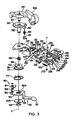
- FIG. 3 is an exploded view of the shift control device
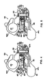
- FIG. 4 is a cross sectional view of the shift control device in an inoperative state
- FIG. 5 is a cross sectional view of the shift control device showing the linearly operating body in an operating position
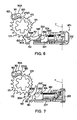
- FIG. 6 is a detailed bottom view of the linearly operating body in a home position
- FIG. 7 is a detailed bottom view of the linearly operating body in an operating position.
- FIGS. 8-11 are top views of relevant components of alternative embodiments of the shift control device.
- FIGS. 1-7 are various views of a particular embodiment of a shift control device 105 according to the present invention.
- shift control device 105 is constructed for pulling and releasing a shift control cable 104, and it includes a mounting bracket 103 with an annular mounting sleeve 103A defining a handlebar mounting axis (HB), wherein mounting sleeve 103A fits around a handlebar 101 to fasten bracket 103 to handlebar 101 in a known manner.
- An arm-shaped linearly sliding operating body 220 (FIGS. 4-7) of shift control device 105 is slidingly mounted to an intermediate bracket 227 attached to mounting bracket 103 through a screw 228.
- Sliding operating body 220 is located below handlebar 101 and terminates at an end 201 forming an abutment.
- An interface member in the form of an operating tab 202 with an operating force receiving surface 203, an operating force applying surface 204 and parallel spaced mounting ears 206 and 208 is pivotably coupled to corresponding parallel spaced mounting ears 210 and 212 on intermediate bracket 227 through a pivot shaft 216 and a C-clip 217, wherein pivot shaft 216 extends through openings 221, 222, 224 and 226 in mounting ears 206, 208, 210 and 212, respectively so that operating tab 202 pivots around a pivot axis (P).
- a decorative cap 232 (FIGS. 1 and 2) having the same general structure as operating tab 202 also may be pivotably mounted to mounting ears 210 and 212 on intermediate bracket 227 or may be otherwise placed over operating tab 202 in order to vary the shape or inclination of the surface that is operated by the thumb.
- a pivoting operating body 130 of the shift control device 105 also extends below the handlebar 101.
- a finger contacting part 132 of operating body 130 in the form of a button, is disposed beneath and to the right of operating tab 202. As a result, operation of both operating bodies is possible with the thumb of the hand gripping the handlebar 101.
- shift control device 105 includes a pawl support plate 106 with a supporting shaft 108 and a pivot pin 152, all of which are rigidly fastened to bracket 103 by means of an attachment bolt 107, a washer 107A and a nut 109.
- a control body in the form of a take-up body 170 is mounted around supporting shaft 108 for rotation around a rotational axis (X).
- a first ratchet mechanism 150 used as a first transmission means, transmits the displacement of sliding operating body 220 to the take-up body 170 to cause the rotation of the take-up body 170 in one direction
- a second ratchet mechanism 160 used as a second transmission means, transmits the displacement of pivoting operating body 130 to the take-up body 170 to cause the rotation of the take-up body 170 in the other direction.
- displacement of pivoting operating body 130 causes the take-up body 170 to pull on cable 104
- displacement of sliding operating body 220 causes the. take-up body 170 to release cable 104.
- the take-up body 170 is equipped with a drum part 169 which is constructed so that the shift control cable 104 from a shifting mechanism (not shown) on the front or rear of the bicycle is taken up along a wire groove 174. By rotating in the forward direction or reverse direction with respect to the supporting shaft 108, the take-up body 170 takes up or pays out the shift control cable 104.
- Take-up body 170 is coupled to a drive plate 171 for integral rotation therewith. As shown in FIGS. 6 and 7, drive plate 171 includes a plurality of drive teeth 173 and a plurality of position retaining teeth 172, all of which are disposed in a common plane (T), as illustrated in FIGS. 4 and 5.
- Sliding operating body 220 includes a pawl pushing roller 250 rotatably mounted between roller support ears 254 and 256 disposed at a pawl operating end 258 of sliding operating body 220 through a pivot shaft 260 and a C-clip 270, wherein pivot shaft 260 extends through openings 264 and 266 in mounting ears 254 and 256, respectively.
- Sliding operating body 220 is slidingly mounted to intermediate bracket 227 between a release plate 274, slide shims 276 and 278, and a release plate bushing 280, all of which are mounted to intermediate bracket 227 through bolts 282 (only one such bolt is shown in FIG.
- Sliding operating body 220 also includes an elongated opening 294 for accommodating bolts 282 so that bolts 282 do not interfere with the sliding operation of sliding operating body 220.
- Release plate 274 includes a spring coupling abutment 298.
- One end of a return spring 300 is attached to spring coupling abutment 298, and the other end of return spring 300 is attached to mounting ear 256 in sliding operating body 220 through an opening 304.
- Return spring 300 biases sliding operating body 220 toward a home position (HP1) shown in FIGS. 4 and 6.
- the first ratchet mechanism 150 comprises a first pawl 151 that is rotatably attached to pivot pin 152 extending from pawl support plate 106, the plurality of position retaining teeth 172 which are formed on the outer circumferential surface of the drive plate 171, and a spring 153 which drives the first pawl 151 clockwise (in FIGS. 6 and 7) in the direction of engagement with position retaining teeth 172.
- First pawl 151 includes pawl tips 151A and 151B for engaging position retaining teeth 172 and a pawl operating part 151C for engaging pawl pushing roller 250 on sliding operating member 220.
- the operation of first ratchet mechanism 150 is the same as in the shift control device disclosed in U.S. Pat. No. 5,921,138, incorporated herein by reference, so a detailed description of its operation shall be omitted.
- the path of motion of sliding operating body 220 is substantially parallel to the ratchet teeth plane (T).
- the pivoting operating body 130 is equipped with a second arm part 131, the second finger contact part 132 which is formed on the tip of the second arm part 131 in order to allow finger operation, and a pawl supporting part 133.
- a spring 111 is connected between washer 107A and pawl supporting part 133 for biasing pivoting operating body 130, and hence finger contacting part 132, to the home position HP2 shown in FIG. 4.
- the path of motion of pivoting operating body 130 is substantially parallel to the ratchet teeth plane (T).
- the second ratchet mechanism 160 comprises a second pawl 161 that is rotatably attached to a pivot pin 162 extending from pawl supporting part 133, the plurality of drive teeth 173 formed on the outer circumferential surface of the drive plate 171, and a spring 163 which biases the second pawl 161 clockwise (in FIGS. 6 and 7) in the direction of engagement with drive teeth 173.
- pivoting operating body 130 is in the home position (HP2) shown in FIGS. 4 and 5
- a tip 161A of pawl 161 rests on a ledge 272D of intermediate bracket 227, thus uncoupling pawl 161 from drive plate 172.
- the operation of second ratchet mechanism 160 also is the same as the shift control device disclosed in U.S. Pat. No. 5,921,138, so a detailed description of its operation shall be omitted.
- sliding operating body 220 operates pawl 151 by pressing pawl pressing roller 250 against pawl operating part 151 C, very little movement (e.g., 9 millimeters) is required to operate pawl 151.
- Operating force receiving surface 203 of operating tab 202 is inclined relative to a horizontal axis (H) which, in this embodiment, is parallel to ratchet teeth plane (T).
- H horizontal axis
- T ratchet teeth plane
- operating tab 202 may operate sliding operating body 220 without requiring the rider to press perpendicular to the handlebar and without precision placement of the rider's thumb. Indeed, even a downward sliding motion of the thumb could operate sliding operating body 220 across the front face of shift control device 105.
- operating body 220 may cause take-up body 170 to rotate in the cable pay out direction
- operating body 130 may cause take-up body 170 to rotate in the cable take-up direction
- operating body 220 may be constructed for pivoting displacement
- operating body 130 may be constructed for sliding displacement with the operating tab 202 described above.
- Both operating bodies 220 and 130 may be sliding operating bodies, each with their own operating tab. While the path of movement of sliding operating body 220 in the above embodiment is substantially parallel to the plane of the ratchet teeth (T), the path may vary, for example, by plus or minus thirty degrees.
- operating tab 202 pivoted around a pivot axis (P) that was substantially parallel to the handlebar axis (HB) in the above embodiments
- the pivot axis (P) could be inclined relative to the handlebar axis (HB) by any degree to accommodate different riding styles.
- the configuration of operating tab 202 also could be changed accordingly. For example, FIG.
- FIG. 8 is a top view of relevant components of an alternative embodiment shift control device 400 wherein an interface member in the form of an operating member 404 with an operating force receiving surface 405 and an operating force applying surface 406 is connected to the right side of intermediate bracket 227 through a pivot shaft 408 so that operating member 404 pivots around a pivot axis (P) that is substantially perpendicular to handlebar axis (HB) and is substantially parallel to rotational axis (X). Also, operating member 404 moves in a direction toward a plane (PL) that contains the handlebar mounting axis (HB) and is parallel with the rotational axis (X) when sliding operating body 220 moves from the home position toward the shift position. In this case, the cyclist may operate sliding operating body 220 by a leftward and/or forward sliding motion of the thumb or finger, thereby pressing operating member 404 toward handlebar axis (HB).
- P pivot axis
- HB handlebar mounting axis
- X rotational axis
- FIG. 9 is a top view of relevant components of another alternative embodiment shift control device 420 wherein an interface member in the form of a fan-shaped operating member 424 with an operating force receiving surface 425 and an operating force applying surface 426 is connected to the left side of intermediate bracket 227 through a pivot shaft 428 so that operating member 424 pivots around a pivot axis (P) that is substantially perpendicular to handlebar axis (HB) and is substantially parallel to rotational axis (X).
- Operating member 424 also moves in a direction toward plane (PL) when sliding operating body 220 moves from the home position toward the shift position.
- the cyclist may operate sliding operating body 220 by a rightward and/or forward sliding motion of the thumb or finger, thereby pressing operating member 424 toward handlebar axis (HB).
- FIG. 10 is a top view of relevant components of another alternative embodiment shift control device 430 wherein an interface member in the form of a lever-shaped operating member 434 with an operating force receiving surface 435 and an operating force applying surface 436 is connected to the right side of intermediate bracket 227 through a pivot shaft 438 so that operating member 434 pivots around a pivot axis (P) that is substantially perpendicular to handlebar axis (HB) and is substantially parallel to rotational axis (X). Operating member 434 also moves in a direction toward plane (PL) when sliding operating body 220 moves from the home position toward the shift position.
- P pivot axis
- HB handlebar axis
- X rotational axis
- operating member 434 is an L-shaped member having an operating force receiving member 437 extending from pivot shaft 438 and an operating force applying member 439 extending from pivot shaft 438 substantially perpendicular to operating force receiving member 437 such that pivot shaft 438 is located at the junction of operating force receiving member 437 and operating force applying member 439, and operating force applying surface 436 is disposed in front of handlebar axis (HB).
- the cyclist may operate sliding operating body 220 by a rearward and/or lateral sliding motion of the thumb or finger, thereby pressing operating force receiving member 437 toward handlebar axis (HB).
- FIG. 11 is a top view of relevant components of another alternative embodiment shift control device 440 wherein an interface member in the form of a lever-shaped operating member 444 with an operating force receiving surface 445 and an operating force applying surface 446 is connected to the right side of intermediate bracket 227 through a pivot shaft 448 so that operating member 444 pivots around a pivot axis (P) that is substantially perpendicular to handlebar axis (HB) and is substantially parallel to rotational axis (X). Operating member 444 also moves in a direction toward plane (PL) when sliding operating body 220 moves from the home position toward the shift position.
- P pivot axis
- HB handlebar axis
- X rotational axis
- operating member 444 is an L-shaped member having an operating force receiving member 447 extending from pivot shaft 448 and an operating force applying member 449 extending from pivot shaft 448 substantially perpendicular to operating force receiving member 447 such that pivot shaft 448 is located at the junction of operating force receiving member 447 and operating force applying member 449, and operating force applying surface 446 is disposed behind handlebar axis (HB).
- the cyclist may operate sliding operating body 220 by a forward and/or lateral sliding motion of the thumb or finger, thereby pressing operating force receiving member 447 toward handlebar axis (HB).
Landscapes
- Engineering & Computer Science (AREA)
- Mechanical Engineering (AREA)
- General Engineering & Computer Science (AREA)
- Chemical & Material Sciences (AREA)
- Combustion & Propulsion (AREA)
- Transportation (AREA)
- Mechanical Control Devices (AREA)
- Steering Devices For Bicycles And Motorcycles (AREA)
- Arrangement Or Mounting Of Control Devices For Change-Speed Gearing (AREA)
Applications Claiming Priority (1)
| Application Number | Priority Date | Filing Date | Title |
|---|---|---|---|
| US10/711,702 US8549954B2 (en) | 2004-09-30 | 2004-09-30 | Bicycle shift device having a linearly sliding shift lever operated by a pivoting interface member |
Publications (4)
| Publication Number | Publication Date |
|---|---|
| EP1642821A2 true EP1642821A2 (fr) | 2006-04-05 |
| EP1642821A3 EP1642821A3 (fr) | 2006-06-28 |
| EP1642821B1 EP1642821B1 (fr) | 2008-07-02 |
| EP1642821B2 EP1642821B2 (fr) | 2013-01-16 |
Family
ID=35219691
Family Applications (1)
| Application Number | Title | Priority Date | Filing Date |
|---|---|---|---|
| EP05290709A Expired - Lifetime EP1642821B2 (fr) | 2004-09-30 | 2005-03-30 | Dispositif de commande des changements de vitesses pour bicyclette |
Country Status (7)
| Country | Link |
|---|---|
| US (2) | US8549954B2 (fr) |
| EP (1) | EP1642821B2 (fr) |
| JP (1) | JP2006103672A (fr) |
| CN (1) | CN100417571C (fr) |
| BR (1) | BRPI0502827A (fr) |
| DE (1) | DE602005007822D1 (fr) |
| TW (1) | TWI284181B (fr) |
Cited By (1)
| Publication number | Priority date | Publication date | Assignee | Title |
|---|---|---|---|---|
| EP3398845A4 (fr) * | 2015-12-29 | 2019-08-28 | S-Ride Bicycle Components (Foshan) Co., Ltd. | Dérailleur de bicyclette |
Families Citing this family (4)
| Publication number | Priority date | Publication date | Assignee | Title |
|---|---|---|---|---|
| US6450060B1 (en) * | 2000-03-17 | 2002-09-17 | Shimano, Inc. | Bicycle shift device having a linearly sliding shift lever operated by a pivoting cover |
| US20060066073A1 (en) * | 2004-09-17 | 2006-03-30 | Charles Schuft | Pedal drive |
| US9227689B2 (en) * | 2008-01-08 | 2016-01-05 | Shimano Inc. | Bicycle shift operating device |
| US10017224B2 (en) * | 2008-01-08 | 2018-07-10 | Shimano Inc. | Bicycle shift operating device |
Citations (1)
| Publication number | Priority date | Publication date | Assignee | Title |
|---|---|---|---|---|
| US5921138A (en) | 1996-02-14 | 1999-07-13 | Shimano, Inc. | Bicycle shift device having a linearly sliding shift lever |
Family Cites Families (29)
| Publication number | Priority date | Publication date | Assignee | Title |
|---|---|---|---|---|
| US3901095A (en) † | 1974-06-17 | 1975-08-26 | Joseph W Wechsler | Bicycle gear shift |
| EP0352732B1 (fr) † | 1988-07-29 | 1995-02-15 | Shimano Inc. | Levier de changement de vitesse monté sur le guidon |
| US5012692A (en) | 1988-09-24 | 1991-05-07 | Shimano Industrial Company Limited | Change-speed lever apparatus for use in bicycle |
| US5044213A (en) | 1988-11-29 | 1991-09-03 | Shimano Industrial Co., Ltd. | Speed control apparatus for a bicycle |
| US5241878A (en) | 1988-11-29 | 1993-09-07 | Shimano, Inc. | Bicycle control device |
| US5400675A (en) | 1988-11-29 | 1995-03-28 | Shimano, Inc. | Bicycle control device |
| JP3065656B2 (ja) | 1990-11-14 | 2000-07-17 | 株式会社シマノ | 自転車用変速操作装置 |
| CN2143196Y (zh) * | 1992-12-09 | 1993-10-06 | 日驰企业股份有限公司 | 自行车变速器控制器 |
| TW211548B (en) † | 1993-03-09 | 1993-08-21 | Shimano Kk | Speed changing device of a bicycle |
| JP2606246Y2 (ja) | 1993-06-17 | 2000-10-10 | 株式会社シマノ | 自転車用変速操作装置 |
| CN2184640Y (zh) * | 1993-06-28 | 1994-12-07 | 深圳力宇车料有限公司 | 拨动式自行车变速控制器 |
| JP3644603B2 (ja) | 1994-02-23 | 2005-05-11 | 株式会社シマノ | 自転車用の変速操作装置 |
| JP3644604B2 (ja) † | 1994-03-07 | 2005-05-11 | 株式会社シマノ | 自転車用変速操作装置 |
| JP3501509B2 (ja) | 1994-08-23 | 2004-03-02 | 株式会社シマノ | 自転車用変速操作装置 |
| US5730030A (en) | 1996-01-19 | 1998-03-24 | Shimano, Inc. | Shifting apparatus for bicycles having a brake operating unit disposed between first and second shifting levers |
| US5829313A (en) * | 1997-01-13 | 1998-11-03 | Shimano Inc. | Bicycle derailleur shifting mechanism having indexing configured for use with variety of chain sprocket sets |
| DE19809113A1 (de) | 1998-03-04 | 1999-09-09 | Sram De Gmbh | Schalter für Fahrradgetriebe |
| US6155132A (en) * | 1999-01-28 | 2000-12-05 | Shimano Inc. | Shifting unit for a bicycle |
| DE19915336A1 (de) | 1999-04-03 | 2000-10-05 | Sram De Gmbh | Schalter für ein Fahrradgetriebe |
| US6453764B1 (en) * | 2000-03-03 | 2002-09-24 | Shimano, Inc. | Switch style bicycle shift control device |
| US6450060B1 (en) | 2000-03-17 | 2002-09-17 | Shimano, Inc. | Bicycle shift device having a linearly sliding shift lever operated by a pivoting cover |
| IT1320588B1 (it) | 2000-08-08 | 2003-12-10 | Campagnolo Srl | Gruppo di comando cambio e freno per una bicicletta da corsa, conpulsante di controllo del modo di funzionamento di un display. |
| ITTO20011079A1 (it) | 2001-11-16 | 2003-05-16 | Campagnolo Srl | ,,dispositivo di comando del cambio per una bicicletta avente un manubrio con estremita' diritte,, |
| US6694840B2 (en) | 2002-01-10 | 2004-02-24 | Shimano Inc. | Bicycle shift operating device for bicycle transmission |
| US7146874B2 (en) * | 2002-07-05 | 2006-12-12 | Shimano, Inc. | Shift control device for a bicycle transmission |
| US7152497B2 (en) * | 2003-01-27 | 2006-12-26 | Shimano, Inc. | Method and apparatus for shifting a bicycle transmission by multiple steps |
| DE102004014035A1 (de) † | 2004-03-19 | 2005-10-06 | Sram Deutschland Gmbh | Fahrrad-Gangschaltungseinrichtung |
| US20070068312A1 (en) * | 2005-09-07 | 2007-03-29 | Shimano Inc. | Bicycle shift control mechanism |
| US9701365B2 (en) * | 2007-12-28 | 2017-07-11 | Shimano Inc. | Bicycle shift operating device |
-
2004
- 2004-09-30 US US10/711,702 patent/US8549954B2/en not_active Expired - Fee Related
-
2005
- 2005-03-28 TW TW094109574A patent/TWI284181B/zh not_active IP Right Cessation
- 2005-03-30 EP EP05290709A patent/EP1642821B2/fr not_active Expired - Lifetime
- 2005-03-30 DE DE602005007822T patent/DE602005007822D1/de not_active Expired - Lifetime
- 2005-04-29 CN CNB2005100690192A patent/CN100417571C/zh not_active Expired - Fee Related
- 2005-07-12 BR BRPI0502827-2A patent/BRPI0502827A/pt not_active IP Right Cessation
- 2005-09-22 JP JP2005275127A patent/JP2006103672A/ja not_active Withdrawn
-
2013
- 2013-07-08 US US13/936,917 patent/US8770059B2/en not_active Expired - Lifetime
Patent Citations (1)
| Publication number | Priority date | Publication date | Assignee | Title |
|---|---|---|---|---|
| US5921138A (en) | 1996-02-14 | 1999-07-13 | Shimano, Inc. | Bicycle shift device having a linearly sliding shift lever |
Cited By (1)
| Publication number | Priority date | Publication date | Assignee | Title |
|---|---|---|---|---|
| EP3398845A4 (fr) * | 2015-12-29 | 2019-08-28 | S-Ride Bicycle Components (Foshan) Co., Ltd. | Dérailleur de bicyclette |
Also Published As
| Publication number | Publication date |
|---|---|
| CN100417571C (zh) | 2008-09-10 |
| JP2006103672A (ja) | 2006-04-20 |
| US20060070478A1 (en) | 2006-04-06 |
| US20130291674A1 (en) | 2013-11-07 |
| EP1642821B1 (fr) | 2008-07-02 |
| US8549954B2 (en) | 2013-10-08 |
| TWI284181B (en) | 2007-07-21 |
| DE602005007822D1 (de) | 2008-08-14 |
| EP1642821A3 (fr) | 2006-06-28 |
| BRPI0502827A (pt) | 2006-05-09 |
| TW200610901A (en) | 2006-04-01 |
| EP1642821B2 (fr) | 2013-01-16 |
| US8770059B2 (en) | 2014-07-08 |
| CN1754765A (zh) | 2006-04-05 |
Similar Documents
| Publication | Publication Date | Title |
|---|---|---|
| US6450060B1 (en) | Bicycle shift device having a linearly sliding shift lever operated by a pivoting cover | |
| EP1449756B1 (fr) | Dispositif de commande pour bicyclette | |
| US5921138A (en) | Bicycle shift device having a linearly sliding shift lever | |
| US7267026B2 (en) | Bicycle control device | |
| US9132887B2 (en) | Bicycle operating device | |
| US5617761A (en) | Shifting apparatus for a bicycle | |
| US8770059B2 (en) | Bicycle shift device having a linearly sliding shift lever operated by a pivoting interface member | |
| US8720301B2 (en) | Bicycle operating device | |
| US20080314191A1 (en) | Bicycle control device | |
| US9932091B2 (en) | Bicycle operating device | |
| US9016163B2 (en) | Bicycle control device | |
| EP2065298A1 (fr) | Dispositif de commande d'une bicyclette | |
| US8869648B2 (en) | Bicycle brake and shift operating device | |
| EP1705110B1 (fr) | Dispositif de commande pour bicyclette | |
| US8881619B2 (en) | Bicycle control device | |
| US8746105B2 (en) | Bicycle operating device | |
| US20080314184A1 (en) | Bicycle control device | |
| US20080314185A1 (en) | Bicycle control device | |
| US7762157B2 (en) | Bicycle shift operating device with a multi-direction operating member | |
| US20140109718A1 (en) | Bicycle control device | |
| TWM376514U (en) | Bicycle component operating device | |
| US7779719B2 (en) | Combination of derailleur shifter and brake lever | |
| JPS5943191Y2 (ja) | 自転車用変速操作装置 |
Legal Events
| Date | Code | Title | Description |
|---|---|---|---|
| PUAI | Public reference made under article 153(3) epc to a published international application that has entered the european phase |
Free format text: ORIGINAL CODE: 0009012 |
|
| AK | Designated contracting states |
Kind code of ref document: A2 Designated state(s): AT BE BG CH CY CZ DE DK EE ES FI FR GB GR HU IE IS IT LI LT LU MC NL PL PT RO SE SI SK TR |
|
| AX | Request for extension of the european patent |
Extension state: AL BA HR LV MK YU |
|
| PUAL | Search report despatched |
Free format text: ORIGINAL CODE: 0009013 |
|
| AK | Designated contracting states |
Kind code of ref document: A3 Designated state(s): AT BE BG CH CY CZ DE DK EE ES FI FR GB GR HU IE IS IT LI LT LU MC NL PL PT RO SE SI SK TR |
|
| AX | Request for extension of the european patent |
Extension state: AL BA HR LV MK YU |
|
| RAP1 | Party data changed (applicant data changed or rights of an application transferred) |
Owner name: SHIMANO INC. |
|
| 17P | Request for examination filed |
Effective date: 20060712 |
|
| 17Q | First examination report despatched |
Effective date: 20060904 |
|
| AKX | Designation fees paid |
Designated state(s): DE NL |
|
| GRAP | Despatch of communication of intention to grant a patent |
Free format text: ORIGINAL CODE: EPIDOSNIGR1 |
|
| GRAS | Grant fee paid |
Free format text: ORIGINAL CODE: EPIDOSNIGR3 |
|
| GRAA | (expected) grant |
Free format text: ORIGINAL CODE: 0009210 |
|
| AK | Designated contracting states |
Kind code of ref document: B1 Designated state(s): DE NL |
|
| REF | Corresponds to: |
Ref document number: 602005007822 Country of ref document: DE Date of ref document: 20080814 Kind code of ref document: P |
|
| PLBI | Opposition filed |
Free format text: ORIGINAL CODE: 0009260 |
|
| PLAX | Notice of opposition and request to file observation + time limit sent |
Free format text: ORIGINAL CODE: EPIDOSNOBS2 |
|
| 26 | Opposition filed |
Opponent name: SRAM DEUTSCHLAND GMBH Effective date: 20090401 |
|
| NLR1 | Nl: opposition has been filed with the epo |
Opponent name: SRAM DEUTSCHLAND GMBH |
|
| PLAF | Information modified related to communication of a notice of opposition and request to file observations + time limit |
Free format text: ORIGINAL CODE: EPIDOSCOBS2 |
|
| PLAF | Information modified related to communication of a notice of opposition and request to file observations + time limit |
Free format text: ORIGINAL CODE: EPIDOSCOBS2 |
|
| PLAB | Opposition data, opponent's data or that of the opponent's representative modified |
Free format text: ORIGINAL CODE: 0009299OPPO |
|
| PLBB | Reply of patent proprietor to notice(s) of opposition received |
Free format text: ORIGINAL CODE: EPIDOSNOBS3 |
|
| PGFP | Annual fee paid to national office [announced via postgrant information from national office to epo] |
Ref country code: NL Payment date: 20100316 Year of fee payment: 6 |
|
| REG | Reference to a national code |
Ref country code: NL Ref legal event code: V1 Effective date: 20111001 |
|
| PG25 | Lapsed in a contracting state [announced via postgrant information from national office to epo] |
Ref country code: NL Free format text: LAPSE BECAUSE OF NON-PAYMENT OF DUE FEES Effective date: 20111001 |
|
| PUAH | Patent maintained in amended form |
Free format text: ORIGINAL CODE: 0009272 |
|
| STAA | Information on the status of an ep patent application or granted ep patent |
Free format text: STATUS: PATENT MAINTAINED AS AMENDED |
|
| 27A | Patent maintained in amended form |
Effective date: 20130116 |
|
| AK | Designated contracting states |
Kind code of ref document: B2 Designated state(s): DE NL |
|
| REG | Reference to a national code |
Ref country code: DE Ref legal event code: R102 Ref document number: 602005007822 Country of ref document: DE Effective date: 20130116 |
|
| PGFP | Annual fee paid to national office [announced via postgrant information from national office to epo] |
Ref country code: DE Payment date: 20190319 Year of fee payment: 15 |
|
| REG | Reference to a national code |
Ref country code: DE Ref legal event code: R119 Ref document number: 602005007822 Country of ref document: DE |
|
| PG25 | Lapsed in a contracting state [announced via postgrant information from national office to epo] |
Ref country code: DE Free format text: LAPSE BECAUSE OF NON-PAYMENT OF DUE FEES Effective date: 20201001 |