EP1643004B1 - Behandlungsvorrichtung mit verwendung von ausgangsstoffgas und reaktivem gas - Google Patents
Behandlungsvorrichtung mit verwendung von ausgangsstoffgas und reaktivem gas Download PDFInfo
- Publication number
- EP1643004B1 EP1643004B1 EP04732754A EP04732754A EP1643004B1 EP 1643004 B1 EP1643004 B1 EP 1643004B1 EP 04732754 A EP04732754 A EP 04732754A EP 04732754 A EP04732754 A EP 04732754A EP 1643004 B1 EP1643004 B1 EP 1643004B1
- Authority
- EP
- European Patent Office
- Prior art keywords
- gas
- reactive
- reactive gas
- source gas
- valve
- Prior art date
- Legal status (The legal status is an assumption and is not a legal conclusion. Google has not performed a legal analysis and makes no representation as to the accuracy of the status listed.)
- Expired - Lifetime
Links
Images




Classifications
-
- C—CHEMISTRY; METALLURGY
- C23—COATING METALLIC MATERIAL; COATING MATERIAL WITH METALLIC MATERIAL; CHEMICAL SURFACE TREATMENT; DIFFUSION TREATMENT OF METALLIC MATERIAL; COATING BY VACUUM EVAPORATION, BY SPUTTERING, BY ION IMPLANTATION OR BY CHEMICAL VAPOUR DEPOSITION, IN GENERAL; INHIBITING CORROSION OF METALLIC MATERIAL OR INCRUSTATION IN GENERAL
- C23C—COATING METALLIC MATERIAL; COATING MATERIAL WITH METALLIC MATERIAL; SURFACE TREATMENT OF METALLIC MATERIAL BY DIFFUSION INTO THE SURFACE, BY CHEMICAL CONVERSION OR SUBSTITUTION; COATING BY VACUUM EVAPORATION, BY SPUTTERING, BY ION IMPLANTATION OR BY CHEMICAL VAPOUR DEPOSITION, IN GENERAL
- C23C16/00—Chemical coating by decomposition of gaseous compounds, without leaving reaction products of surface material in the coating, i.e. chemical vapour deposition [CVD] processes
- C23C16/44—Chemical coating by decomposition of gaseous compounds, without leaving reaction products of surface material in the coating, i.e. chemical vapour deposition [CVD] processes characterised by the method of coating
- C23C16/455—Chemical coating by decomposition of gaseous compounds, without leaving reaction products of surface material in the coating, i.e. chemical vapour deposition [CVD] processes characterised by the method of coating characterised by the method used for introducing gases into reaction chamber or for modifying gas flows in reaction chamber
- C23C16/45561—Gas plumbing upstream of the reaction chamber
-
- C—CHEMISTRY; METALLURGY
- C23—COATING METALLIC MATERIAL; COATING MATERIAL WITH METALLIC MATERIAL; CHEMICAL SURFACE TREATMENT; DIFFUSION TREATMENT OF METALLIC MATERIAL; COATING BY VACUUM EVAPORATION, BY SPUTTERING, BY ION IMPLANTATION OR BY CHEMICAL VAPOUR DEPOSITION, IN GENERAL; INHIBITING CORROSION OF METALLIC MATERIAL OR INCRUSTATION IN GENERAL
- C23C—COATING METALLIC MATERIAL; COATING MATERIAL WITH METALLIC MATERIAL; SURFACE TREATMENT OF METALLIC MATERIAL BY DIFFUSION INTO THE SURFACE, BY CHEMICAL CONVERSION OR SUBSTITUTION; COATING BY VACUUM EVAPORATION, BY SPUTTERING, BY ION IMPLANTATION OR BY CHEMICAL VAPOUR DEPOSITION, IN GENERAL
- C23C16/00—Chemical coating by decomposition of gaseous compounds, without leaving reaction products of surface material in the coating, i.e. chemical vapour deposition [CVD] processes
- C23C16/44—Chemical coating by decomposition of gaseous compounds, without leaving reaction products of surface material in the coating, i.e. chemical vapour deposition [CVD] processes characterised by the method of coating
- C23C16/4412—Details relating to the exhausts, e.g. pumps, filters, scrubbers, particle traps
-
- C—CHEMISTRY; METALLURGY
- C23—COATING METALLIC MATERIAL; COATING MATERIAL WITH METALLIC MATERIAL; CHEMICAL SURFACE TREATMENT; DIFFUSION TREATMENT OF METALLIC MATERIAL; COATING BY VACUUM EVAPORATION, BY SPUTTERING, BY ION IMPLANTATION OR BY CHEMICAL VAPOUR DEPOSITION, IN GENERAL; INHIBITING CORROSION OF METALLIC MATERIAL OR INCRUSTATION IN GENERAL
- C23C—COATING METALLIC MATERIAL; COATING MATERIAL WITH METALLIC MATERIAL; SURFACE TREATMENT OF METALLIC MATERIAL BY DIFFUSION INTO THE SURFACE, BY CHEMICAL CONVERSION OR SUBSTITUTION; COATING BY VACUUM EVAPORATION, BY SPUTTERING, BY ION IMPLANTATION OR BY CHEMICAL VAPOUR DEPOSITION, IN GENERAL
- C23C16/00—Chemical coating by decomposition of gaseous compounds, without leaving reaction products of surface material in the coating, i.e. chemical vapour deposition [CVD] processes
- C23C16/44—Chemical coating by decomposition of gaseous compounds, without leaving reaction products of surface material in the coating, i.e. chemical vapour deposition [CVD] processes characterised by the method of coating
- C23C16/52—Controlling or regulating the coating process
-
- H—ELECTRICITY
- H10—SEMICONDUCTOR DEVICES; ELECTRIC SOLID-STATE DEVICES NOT OTHERWISE PROVIDED FOR
- H10P—GENERIC PROCESSES OR APPARATUS FOR THE MANUFACTURE OR TREATMENT OF DEVICES COVERED BY CLASS H10
- H10P14/00—Formation of materials, e.g. in the shape of layers or pillars
- H10P14/40—Formation of materials, e.g. in the shape of layers or pillars of conductive or resistive materials
- H10P14/42—Formation of materials, e.g. in the shape of layers or pillars of conductive or resistive materials using a gas or vapour
- H10P14/43—Chemical deposition, e.g. chemical vapour deposition [CVD]
-
- H—ELECTRICITY
- H10—SEMICONDUCTOR DEVICES; ELECTRIC SOLID-STATE DEVICES NOT OTHERWISE PROVIDED FOR
- H10P—GENERIC PROCESSES OR APPARATUS FOR THE MANUFACTURE OR TREATMENT OF DEVICES COVERED BY CLASS H10
- H10P14/00—Formation of materials, e.g. in the shape of layers or pillars
- H10P14/40—Formation of materials, e.g. in the shape of layers or pillars of conductive or resistive materials
- H10P14/42—Formation of materials, e.g. in the shape of layers or pillars of conductive or resistive materials using a gas or vapour
- H10P14/43—Chemical deposition, e.g. chemical vapour deposition [CVD]
- H10P14/432—Chemical deposition, e.g. chemical vapour deposition [CVD] using selective deposition
Definitions
- the present invention relates to a processing apparatus that performs a film-deposition process for, e.g., a semiconductor wafer, by using a source gas and a reactive gas (such as a reducing gas and an oxidizing gas).
- a source gas and a reactive gas such as a reducing gas and an oxidizing gas.
- an object to be processed such as a semiconductor wafer is generally, repeatedly subjected to various kinds of single-wafer processes, such as a film-deposition process, etching process, heat process, modification process, and crystallization process, so as to form a desired integrated circuit.
- a processing gas necessary for a certain process is introduced to a processing vessel. That is, a film-deposition gas is introduced to a processing vessel when a film-deposition process is performed.
- an ozone gas is introduced for performing a modification processing
- an inert gas such as N 2 gas or O 2 gas is introduced for performing a crystallization process.
- a table incorporating, e.g., a resistance heater is disposed in a processing vessel capable of forming a vacuum.
- a predetermined processing gas is fed into the vessel, with a semiconductor wafer being disposed on an upper surface of the table, so that the wafer is subjected to various kinds of heat processes under predetermined process conditions (for example, Japanese Patent Laid-Open Publication No. 2002-256440 ).
- metal such as W (tungsten), WSi (tungsten silicide), Ti (titanium), TiN (titanium nitride), TiSi (titanium silicide), Cu (copper), and Ta 2 O 5 (tantalum oxide) or a metal compound is used to deposit a thin film in the recesses.
- a tungsten film is especially employed, because of its small specific resistance and a low temperature required for forming a film.
- WF 6 hexafluoro tungsten used as a source gas is reduced by hydrogen, silane, dichlorosilane or the like, so as to deposit a tungsten film.
- a source gas of a halogen metal compound such as ZrCl 4 or ZrBr 4 , and a reactive gas such as ozone or H 2 O 2 are used to deposit a high dielectric film (Japanese Patent Laid-Open Publication No. 2002-151489 ).
- Japanese Patent Laid-Open Publication No. 2002-151489 discloses the following processing method, in which a film-thickness of a film deposited on a wafer is reduced, while maintaining a high intrafilm uniformity of the film-thickness and a high electric property of the deposited film. That is, a substrate holder incorporating a resistance heater is disposed in a processing vessel capable of forming a vacuum.
- a plurality of processing gases of different kinds are intermittently, alternately caused to flow in the processing vessel, so as to repeatedly deposit a ZrO 2 film of a thickness about a single molecular layer on a surface of a semiconductor wafer held on the substrate holder.
- a pre-flow operation for causing a gas to flow for only a few seconds must be carried out for each time immediately before a gas is actually supplied to the processing vessel. This is because the pre-flow operation stabilizes a gas flow rate so that a uniformity of a film-thickness or the like can be improved.
- a gas used for the pre-flow operation does not pass through the processing vessel, but bypasses the same to be directly discharged to a vacuum evacuating system.
- a processing vessel 2 containing a semiconductor wafer W can be evacuated to form a vacuum by a vacuum evacuating system 6 provided with a vacuum pump 4.
- a source gas supply system 8 and a reactive gas supply system 10 are connected to the processing vessel 2.
- the source gas supply system 8 supplies, e.g., ZrCl 4 as a source gas
- the reactive gas supply system 10 supplies, e.g., ozone (O 3 ) as a reactive gas.
- a by-pass pipe 12 communicates the gas supply system 8 to the vacuum evacuating system 6, and a by-pass pipe 14 communicates the gas supply system 10 to the vacuum evacuating system 6.
- a scrubber 5 for burning a gas remaining in an evacuated gas to eliminate the same is disposed in the vacuum evacuating system 6.
- the source gas supply system 8, the reactive gas supply system 10, and the by-pass pipes 12 and 14 are respectively provided with switching valves V1 to V4.
- the ZrCl 4 gas and the O 3 gas whose flow rates are respectively controlled by respective mass flow controllers MFC are alternately, intermittently fed into the processing vessel 2, as shown in Fig. 9 .
- thin films are deposited on the wafer W one by one.
- a pre-flow operation is carried out for a few seconds, immediately before each gas is supplied on a pulse basis.
- a gas used for the pre-flow operation passes through the by-pass pipe 12 or 14 to be directly discharged to the vacuum evacuating system 6, without passing through the processing vessel 2.
- the gases are independently fed into the processing vessel 2.
- the gases simultaneously flow into the vacuum evacuating system 6 provided with the vacuum pump 4.
- the gases react to each other in the vacuum pump 4 to generate deposits.
- the deposits adhere to a rotational driving system in the vacuum pump 4, which may cause a damage in the vacuum pump 4.
- the inside of the vacuum pump 4 is not raised to a process temperature of, e.g., about 410°C
- the temperature in the vacuum pump 4 is easily raised to a some degree, i.e., about 100°C to 190°C, by a gas compression.
- generation of deposits is further promoted.
- An object of the present invention is to provide a processing apparatus that does not allow a source gas and a reactive gas to simultaneously flow into a vacuum evacuating system, so that generation of unwanted deposits which may cause a malfunction of a vacuum pump can be prevented.
- Another object of the present invention is to provide a processing apparatus that can restrain a maintenance frequency of a trap device for removing an impurity gas from an evacuated gas.
- a processing apparatus comprising:
- a source gas and a reactive gas are not allowed to simultaneously flow into the vacuum pump of the vacuum evacuating system through the respective by-pass lines.
- a source gas and a reactive gas are not allowed to simultaneously flow into the vacuum pump of the vacuum evacuating system through the respective by-pass lines.
- the processing apparatus further comprises a gas supply controller that controls the source gas supply system, the reactive gas supply system and the on-off valve, such that the source gas and the reactive gas are not allowed to simultaneously flow into the vacuum evacuating system.
- a processing apparatus comprising:
- the source gas by-pass line is provided with a source gas buffer tank, while the reactive gas by-pass line is provided with a reactive gas buffer tank.
- the reactive gas may be a reducing gas or an oxidation gas.
- the source gas is WF 6 gas
- the reducing gas is a silane-group gas or hydrogen gas.
- the vacuum evacuating system is provided with a scrubber that eliminates an impurity gas in an evacuated gas.
- a scrubber that eliminates an impurity gas in an evacuated gas.
- a first embodiment of the present invention shown in Figs. 1 to 3 are described at first.
- a process in which a tungsten film (seeding film) is formed by supplying alternately, intermittently WF 6 gas as a source gas and SiH 4 gas of a reducing gas as a reactive gas is described as an example.
- a processing apparatus 20 includes a cylindrical processing vessel 22 an inside of which can be evacuated to form a vacuum.
- a table 24 is disposed in the processing vessel 22.
- An object to be processed, such as a semiconductor wafer W, can be supported on an upper surface of the table 24.
- a resistance heater 26 as heating means is buried in the table 24, so that the wafer W can be heated to a predetermined temperature and maintained thereat. In place of the resistance heater, a heating lamp may be used as the heating means.
- a gate valve 28 is disposed on a sidewall of the processing vessel 22, which is opened and closed when the wafer W is loaded into the processing vessel 22 and unloaded therefrom.
- Gas-introducing means such as a showerhead part 30, for introducing various gases required for a wafer processing to the processing vessel 22 is disposed on a top part of the processing vessel 22.
- Each of the gases can be jetted through a plurality of gas jetting holes 30A, so as to be introduced to the processing vessel 22.
- the plurality of gas jetting holes 30A are arranged in matrix.
- An inside of the showerhead part 30 may be constituted to form one diffusion chamber, or a plurality of separated diffusion chambers to prevent gases from mixing in the showerhead part 30.
- the gases are not mixed with each other until the gases are jetted from the gas jetting holes 30A.
- This gas supply condition is referred to as "post-mix”.
- gases are supplied in the post-mix manner in this embodiment.
- the gas-introducing means is not limited to such a showerhead structure, and a gas can be supplied through a nozzle.
- An exhaust port 34 is formed in a bottom part 32 of the processing vessel 22.
- a vacuum evacuating system 36 for exhausting an atmosphere in the processing vessel 22 to form therein a vacuum is connected to the exhaust port 34.
- the vacuum evacuating system 36 is provided with an exhaust pipe 38 of relatively a larger diameter, which is connected to the exhaust port 34.
- the exhaust pipe 38 is provided with: a pressure control valve 40 formed of a butterfly valve whose valve opening can be adjusted to control a pressure in the processing vessel 22; a shut-off valve 42 for opening/closing the exhaust pipe 38 according to need; an upstream-side vacuum pump 44 formed of, e.g., a mechanical booster pump; and a downstream-side vacuum pump 46 formed of, e.g., a dry pump; which are disposed in this order from an upstream side to a downstream side of the exhaust pipe 38.
- the vacuum evacuating system 36 has a scrubber 47 at a downstream side of the downstream-side vacuum pump 46. The scrubber 47 burns to oxidize and decompose an impurity gas, such as SiH 4 , contained in an evacuated gas so as to eliminate the same.
- the showerhead part 30 is provided with: a source gas supply system 50 for selectively supplying a source gas into the processing vessel 22; and a reactive gas supply system 52 for selectively supplying a reactive gas into the processing vessel 22.
- the showerhead part 30 is provided with: a system for supplying another required gas, such as an H 2 gas supply system 54 for supplying H 2 gas; and an inert gas supply system such as an N 2 gas supply system (not shown) for supplying N 2 gas.
- a carrier gas is added to the source gas and the reactive gas, if necessary.
- WF 6 gas is used as a source gas
- SiH 4 gas of a reducing gas is used as a reactive gas, so as to form a tungsten film by a thermal CVD method.
- the source gas supply system 50 includes a source gas supply pipe 56 which is connected to the showerhead part 30.
- the source gas supply pipe 56 is provided with: a source gas valve 56A; a source gas flow rate controller 56 like a mass flow controller; and a first switching valve X3 for a source gas, which are disposed in this order from an upstream side to a downstream side of the source gas supply pipe 56.
- the reactive gas supply system 52 includes a reactive gas supply pipe 58 which is connected to the showerhead part 30.
- the reactive gas supply pipe 58 is provided with: a reactive gas valve 58A; a reactive gas flow rate controller 58B like a mass flow controller; and a first switching valve Y3 for a reactive gas, which are disposed in this order from an upstream side to a downstream side of the reactive gas supply pipe 58.
- the H 2 gas supply system 54 includes an H 2 gas supply pipe 60 which is connected to the showerhead part 30.
- the H 2 gas supply pipe 60 is provided with: an H 2 gas valve 60A; and an H 2 gas flow rate controller 60B like a mass flow controller; which are disposed in this order from an upstream side to a downstream side of the H 2 gas supply pipe 60.
- a source gas is selectively caused to flow through the source gas by-pass line 62.
- the source gas by-pass line 62 includes a source gas by-pass pipe 64 which is branched from the source gas supply pipe 56 at a position between the source gas flow rate controller 56B and the source gas first switching valve X3.
- a downstream end of the source gas by-pass pipe 64 is connected and communicated to the exhaust pipe 38 at a position between the shut-off valve 42 and the upstream-side vacuum pump 44.
- a second switching valve X2 for a source gas is disposed on an upstream side of the source gas by-pass pipe 64.
- a reactive gas by-pass line 66 bypassing the processing vessel 22 communicates the reactive gas supply system 52 to the vacuum evacuating system 36.
- a reactive gas is selectively caused to flow through the reactive gas by-pass line 66.
- the reactive gas by-pass line 66 includes a reactive gas by-pass pipe 68 which is branched from the reactive gas supply pipe 58 at a position between the reactive gas flow rate controller 58B and the reactive gas first switching valve Y3.
- a downstream end of the reactive gas by-pass pipe 68 is connected and communicated to the exhaust pipe 38 at a position between the shut-off valve 42 and the upstream-side vacuum pump 44.
- a second switching valve Y2 for a reactive gas is disposed on an upstream side of the reactive gas by-pass pipe 68.
- the H 2 gas supply pipe 60 may have a by-pass pipe as described above.
- a source gas escape prevention valve X1 which is a characteristic feature of the present invention, that prevents an escape of a source gas, is disposed on a most downstream side of the source gas by-pass pipe 64, i.e., just in front of a position where the source gas by-pass pipe 64 and the exhaust pipe 38 are converged.
- a source gas buffer tank 70 of a predetermined capacity to meet the need is disposed immediately upstream the source gas escape prevention valve X1.
- the source gas buffer tank 70 can temporarily stores therein a source gas.
- a reactive gas escape prevention valve Y1 which is a characteristic feature of the present invention, that prevents an escape of a reactive gas, is disposed on a most downstream side of the reactive gas by-pass pipe 68, i.e., just in front of a position where the reactive gas by-pass pipe 68 and the exhaust pipe 38 are converged.
- a reactive gas buffer tank 72 of a predetermined capacity to meet the need is disposed immediately upstream the reactive gas escape prevention valve Y1.
- the reactive gas buffer tank 72 can temporarily stores therein a reactive gas.
- a gas supply controller 74 which is formed of a microcomputer or the like, that controls the gas supply systems.
- the gas supply controller 74 directly controls to open and/or close the source gas supply system 50 (including the source gas first switching valve X3), the source gas by-pass line 62 (including the source gas second switching valve X2), the reactive gas supply system 52 (including the reactive gas first switching valve Y3), the reactive gas by-pass line 66 (including the reactive gas second switching valve Y2), the source gas escape prevention valve X1, and the reactive gas escape prevention valve Y1.
- a film-deposition method carried out by the processing apparatus as constituted above is described hereinbelow.
- a film-deposition method is described referring to Fig. 2 , in which an initial tungsten film deposition step for depositing an initial tungsten film for seeding a film is performed at first, and thereafter a main tungsten film deposition step for depositing a main tungsten film is successively performed.
- a process pressure is set at about 1000 Pa
- a process temperature is set at about 410°C.
- the parameters are not limited to these values.
- Fig. 2 is a timing chart showing supply conditions of the gases into the processing vessel 22.
- WF 6 gas as a source gas and SiH 4 gas of a reducing gas as a reactive gas are alternately, intermittently supplied at different timings.
- a WF 6 gas supply step and an SiH 4 gas supply step are alternately performed, and a purge step 80 is carried out between the repeated supply steps.
- the purge step 80 is carried out by supplying N 2 gas and evacuating the remaining gas.
- a supply period T1 for WF 6 gas, a supply period T3 for SiH 4 gas, and a purge period T2 are respectively about 1.5 seconds for each time.
- an initial tungsten film is formed by repeating the predetermined number of cycles, for example, 20 to 30 cycles. Subsequently, WF 6 gas and H 2 gas are simultaneously fed into the processing vessel 22, so that a main tungsten film is formed at a higher film-deposition rate.
- a pre-flow operation is performed for a few seconds, e.g., about three seconds, before WF 6 gas or SiH 4 gas is actually supplied into the processing vessel 22 on the above-described cycle basis.
- the WF 6 gas and the SiH 4 gas used for the pre-flow operation do not pass through the processing vessel 22, but pass through the respective by-pass pipes 64 and 68 to be directly discharged to the vacuum evacuating system 36.
- an opening/closing operation of the respective valves is controlled so as not to allow the WF 6 gas and the SiH 4 gas to simultaneously flow into the vacuum evacuating system 36.
- the source gas first switching valve X3 disposed on the source gas supply pipe 56 is opened, while the source gas second switching valve X2 disposed on the source gas by-pass pipe 64 is closed.
- the source gas first switching valve X3 is closed, while the source gas second switching valve X2 is opened.
- the source gas buffer tank 70 of a predetermined capacity is disposed on the source gas by-pass pipe 64, in order to assure that, when the source gas escape prevention valve X1 is closed, the WF 6 gas can be introduced to the source gas by-pass pipe 64.
- the source gas buffer tank 70 makes it possible for the WF 6 gas to flow as a pre-flow through the source gas by-pass pipe 64, when the source gas escape prevention valve X1 is closed.
- SiH 4 gas is supplied into the reactive gas by-pass pipe 68. That is, in order to supply SiH 4 gas into the processing vessel 22, the reactive gas first switching valve Y3 disposed on the reactive gas supply pipe 58 is opened, while the reactive gas second switching valve Y2 disposed on the reactive gas by-pass pipe 68 is closed.
- the reactive gas first switching valve Y3 is closed, while the reactive gas second switching valve Y2 is opened.
- the reactive gas buffer tank 72 of a predetermined capacity is disposed on the reactive gas by-pass pipe 68, in order to assure that, when the reactive gas escape prevention valve Y1 is closed, the SiH 4 gas can be introduced to the reactive gas by-pass pipe 68.
- the reactive gas buffer tank 72 makes it possible for the SiH 4 gas to flow as a pre-flow through the reactive gas by-pass pipe 68, when the reactive gas escape prevention valve Y1 is closed.
- a timing for discharging the WF 6 gas stored in the buffer tank 70 to the vacuum evacuating system 36 by opening the gas escape prevention valve X1 may be an occasion when WF 6 gas is supplied into the processing vessel 22.
- a timing for discharging the SiH 4 stored in the buffer tank 72 to the vacuum evacuating system 36 by opening the gas escape prevention valve Y1 may be an occasion when SiH 4 gas is supplied into the processing vessel 22.
- Opening/closing operations of the respective valves and flow conditions of the gases are described in detail below with reference to Fig. 3 .
- pre-flow means a condition in which a pre-flow operation is carried out
- flow means a condition in which a flow operation, i.e., a supply of gas into the processing vessel 22 is carried out.
- the pre-flow operation for each gas is carried out for three seconds. After that, the flow operation, in which each gas is fed into the processing vessel 22, is carried out for 1.5 seconds.
- the mark " ⁇ " indicates an open condition of each of the valves and the switching valves, and the mark " ⁇ " indicates a closed condition thereof.
- Diagonal lines mean that a gas is actually fed into the processing vessel 22, the by-pass pipes 64 and 68, and the vacuum pumps 44 and 46. An absence of the diagonal lines means that a gas is not fed thereinto.
- WF 6 gas by opening the valves X1 and X2 and closing the valve X3, WF 6 gas is fed into the by-pass pipe 64 and the vacuum pumps 44 and 46 to carry out the pre-flow operation, so that a flow rate of the WF 6 gas is stabilized.
- SiH 4 gas by closing the valves Y2 and Y3 and opening the valve Y1, the by-pass pipe 68 and the reactive gas buffer tank 72 are sufficiently evacuated to form therein a vacuum, so as to prepare the succeeding pre-flow operation.
- the valve X2 is switched from the open condition to the closed condition, and the valve X3 is switched from the closed condition to the open condition, with the valve X1 being maintained to be opened.
- a flow of the WF 6 gas into the by-pass pipe 64 stops, that is, the pre-flow operation stops.
- WF 6 gas is fed into the processing vessel 22 to carry out the flow operation.
- the WF 6 gas continuously flows into the vacuum pumps 44 and 46.
- the valve X1 since the valve X1 is in the open condition, the WF 6 gas fed into the by-pass pipe 64 and stored in the source gas buffer tank 70 in the preceding pre-flow operation is evacuated and discharged.
- a high vacuum is formed in the by-pass pipe 64 and the source gas buffer tank 70 to prepare the succeeding pre-flow operation.
- the valve Y3 is maintained to be closed so as not to allow SiH 4 gas to flow into the processing vessel 22.
- SiH 4 gas is fed into the reactive gas by-pass pipe 68 and the reactive gas buffer tank 72, both forming a high vacuum, so that the pre-flow operation is carried out.
- the SiH 4 gas is not allowed to flow into the vacuum pumps 44 and 46.
- inner surfaces of the pumps 44 and 46 and the vacuum evacuating system 36 through which the WF 6 gas flows are prevented from deposition of a tungsten film.
- the valve X3 is switched from the open condition to the closed condition, with maintaining the closed condition of the valve X2 and the open condition of the valve X1.
- a supply of WF 6 gas into the processing vessel 22 stops.
- N 2 gas not shown
- the processing vessel 22 is evacuated to discharge the gas remaining therein.
- the WF 6 gas remaining in the processing vessel 22 flows into the vacuum pumps 44 and 46, while the source gas by-pass pipe 64 and the source gas buffer tank 70 are continuously evacuated to form a high vacuum, so as to prepare the succeeding pre-flow operation.
- the conditions in the step 3 are maintained as they are, to continue the pre-flow operation. That is, the step 4 corresponds to the purge step 80 shown in Fig. 2 .
- the valve X1 is switched from the open condition to the closed condition, and the valve X2 is switched from the closed condition to the open condition, with the valve X3 being maintained to be closed.
- WF 6 gas is fed into the source gas by-pass pipe 64 and the source gas buffer tank 70, both forming a high vacuum, so that the pre-flow operation is carried out.
- the valve X1 since the valve X1 is in the closed condition, the WF 6 gas is not allowed to flow into the vacuum pumps 44 and 46. As a result, the inner surfaces of the pumps 44 and 46 through which the SiH 4 gas flows are prevented from deposition of a tungsten film.
- the valves Y1 and Y3 are respectively switched from the closed condition to the open condition, while the valve Y2 is switched from the open condition to the closed condition.
- SiH 4 gas is fed into the processing vessel 22 so that the flow operation is carried out.
- a supply of the SiH 4 gas into the reactive gas by-pass pipe 68 is stopped to complete the pre-flow operation.
- the reactive gas by-pass pipe 68 and the reactive gas buffer tank 72 are evacuated to form a high vacuum, so as to prepare the succeeding pre-flow operation.
- the WF6 gas adhering to the surface of the wafer W in the step 3 and the SiH 4 gas supplied in the step 5 react with each other, so that a thin tungsten film is formed on the wafer surface.
- step 6 as to WF 6 gas, the conditions of the respective valves X1, X2, and X3 are maintained as they are in the step 5, to continue the pre-flow operation.
- the valve Y3 is switched from the open condition to the closed condition, with maintaining the open condition of the valve Y1 and the closed condition of the valve Y2.
- a supply of SiH 4 gas into the processing vessel 22 stops.
- the processing vessel 22 is evacuated to discharge the gas remaining therein.
- the SiH 4 gas remaining in the processing vessel 22 flows into the vacuum pumps 44 and 46, while the reactive gas by-pass pipe 68 and the reactive gas buffer tank 72 are evacuated to form a high vacuum, so as to prepare the succeeding pre-flow operation. That is, the step 6 corresponds to the purge step 80 in Fig. 2 .
- the steps 3 to 6 constitute a single cycle, and the cycle is repeated for the required number of times, e.g., 20 to 30 times.
- a film is deposited by supplying a source gas and a reactive gas (a reducing gas in this embodiment) intermittently, alternately supplied into the processing vessel 22 at different timings in a repeated manner.
- a reactive gas a reducing gas in this embodiment
- Figs. 4 shows a comparative example of the processing apparatus in the first embodiment of the present invention
- Fig. 5 shows opening/closing conditions of the valves and flow conditions of the gases, in the apparatus as a comparative example show in Fig. 4
- Film-deposition processes were respectively carried out by the apparatus in the first embodiment and the apparatus as a comparative example, and the results were compared to each other. The evaluation results are described below.
- the processing apparatus shown in Fig. 4 has the same structure as that of the processing apparatus shown in Fig. 1 , except that the source gas escape prevention valve X1, the source gas buffer tank 70, the reactive gas escape prevention valve Y1, and the reactive gas buffer tank 72 are omitted.
- the same constituent parts are shown by the same reference numbers as in Fig. 1 .
- a heating-type trap was disposed in front of the upstream-side vacuum pump 44 of the vacuum evacuating system 36.
- a film-deposition process was carried out for six hours, while a tungsten film was trapped by the heating-type trap.
- a trapped amount of the tungsten film was 6.7 g.
- substantially no tungsten film was trapped. That is, an effectiveness of the processing apparatus according to the present invention could be confirmed.
- the buffer tanks 70 and 72 are disposed on the by-pass pipes 64 and 68, respectively.
- the buffer tanks 70 and 72 may be omitted, when each of the by-pass pies 64 and 68 has a sufficiently large inner diameter and a sufficient pipe length, so that a pipe capacity corresponding to a capacity of each of the buffer tanks 70 and 72 can be assured.
- each of the buffer tanks 70 and 72 is explained.
- a ratio of a downstream pressure relative to an upstream pressure must be set at equal to or less than 0.5, such that a flow velocity reaching the sonic speed maintains an ultrasonic nozzle state.
- a maximum flow rate of the mass flow controller is 450 sccm, and a time period for the pre-flow operation is 3 seconds.
- a downstream pressure must be maintained at equal to or less than 35,000 Pa.
- a flow amount Pv [Pa ⁇ m 3 ] of the WF 6 gas used for the pre-flow operation is as follows.
- the respective valves may be opened and/or closed by means of a delay timer.
- the source gas escape prevention valve X1 is configured to interlock with the reactive gas first switching valve Y3, such that, for example, when the valve Y3 is switched to be opened, the valve X1 is switched to be closed, and that when the valve Y3 is switched from the open condition to the closed condition, the valve X1 is switched from the closed condition to the open condition, with a delay of 1.5 seconds.
- the reactive gas escape prevention valve Y 1 is configured to interlock with the source gas first switching valve X3, such that, for example, when the valve X3 is switched to be opened, the valve Y1 is switched to be closed, and that when the valve X3 is switched from the open condition to the closed condition, the valve Y1 is switched from the closed condition to the open condition, with a delay of 1.5 seconds.
- the supply period of T1 for WF 6 gas, the supply period of T3 for SiH 4 gas, and the period T2 for the purge step are all set to be 1.5 seconds.
- WF 6 gas is supplied as a source gas and SiH 4 gas of a reducing gas is supplied as a reactive gas.
- a reducing gas is not limited to SiH 4 gas, and may be H 2 gas, disilane, dichlorosilane, and so on.
- an oxidation gas such as O 3 gas may be used as a reactive gas.
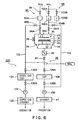
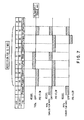
- a second embodiment of the present invention shown in Figs. 6 and 7 is described, with also reference to a conventional example shown in Fig. 10 .
- An object of the second embodiment is to restrain a maintenance frequency of a trap device disposed on a vacuum evacuating system.
- a TiN film is deposited by using TiCl 4 gas and NH 3 gas by a thermal CVD method.
- a constitution of a processing vessel 22 of a conventional processing apparatus shown in Fig. 10 is the same as that of the processing vessel 22 shown in Fig. 1 . Thus, the same parts are shown by the same reference numbers, and their description is omitted.
- a source gas supply system 90 for supplying, for example, TiCl 4 gas as a source gas is connected to a showerhead part 30 disposed in the processing vessel 22.
- a flow rate controller 92A for controlling a flow rate like a mass flow controller is disposed on the source gas supply system 90.
- a valve 94 is disposed upstream the flow rate controller 92A, and a first switching valve 96A is disposed downstream the flow rate controller 92A.
- a reactive gas supply system 98 for supplying, for example, NH 3 gas as a reactive gas is connected to the showerhead part 30.
- NH 3 gas is used at a larger flow rate
- NH 3 gas is used at a smaller flow rate.
- Two flow rate controllers 100A and 100B respectively corresponding to the flow rate ranges are disposed in parallel on the reactive gas supply system 98.
- Valves 102A and 102B are respectively disposed upstream the flow rate controllers 100A and 100B. By switching the valves 102A and 102B, a controlled flow rate range can be selected.
- the flow rate controller 100A controls a larger flow rate range
- the flow rate controller 100B controls a smaller flow rate range.
- a first switching valve 104A is disposed on a most downstream side of the reactive gas supply system 98 but upstream the showerhead part 30.
- a vacuum evacuating system 36 connected to an exhaust port 34 formed in the processing vessel 22 is provided with: a pressure control valve 40; a shut-off valve 42; a trap device 106;, a vacuum pump 108 like a dry pump; and a scrubber 47; which are disposed in this order from an upstream side of the vacuum evacuating system 36.
- the trap device 106 eliminates, from an evacuated gas, an impurity gas such as a remaining source gas and its reactive by-product gas.
- the scrubber 47 eliminates an impurity gas remaining in an evacuated gas by burning the impurity gas, for example.
- NH 3 gas which will react with TiCl 4 gas can be introduced to an upstream side of the trap device 106, when it is required.
- a valve 108A is disposed immediately upstream the trap device 106; and a valve 108B is disposed immediately downstream the trap device 106. The valves 108A and 108B shut off the gas flow channels, during a maintenance operation of the trap device 106.
- a source gas by-pass pipe 110 extends between a position downstream the flow rate controller 92A of the source gas supply system 90 and a position immediately upstream the trap device 106 of the vacuum evacuating system 36.
- a second switching valve 96B is disposed on a most upstream side of the source gas by-pass pipe 110.
- a reactive gas by-pass pipe 112 as a reactive gas by-pass line extends between a position downstream the flow rate controllers 100A and 100B of the reactive gas supply system 98 and a position immediately downstream the trap device 106 of the vacuum evacuating system 36.
- a second switching valve 104B is disposed on a most upstream side of the reactive gas by-pass pipe 112. By switching the first and the second switching valves 104A and 104B, a reactive gas is caused to flow into the processing vessel 22, or bypass the same by passing through reactive gas by-pass pipe 112.
- the reactive gas by-pass pipe 112 is mainly used to stabilize a reactive gas flow, by allowing a reactive gas to flow therethrough in place of the processing vessel 22.
- a downstream end of the reactive by-pass pipe 112 is connected to a position downstream the trap device 106. This is because, since NH 3 gas flowing through the reactive by-pass pipe 112 generates no reactive by-product, the NH 3 gas can be discharged without passing through the trap device 106.
- the trap device 106 removes TiCl 4 gas and a reactive by-product thereof such as NH 4 Cl, TiClx (titanium chloride), and TiO 2 (titanium oxide).
- the TiCl 4 gas which has been supplied into the processing vessel 22 for an actual film deposition and remains therein to be discharged, a reactive by-product gas of the TiCl 4 gas, and the TiCl 4 gas which has been fed into the source gas by-pass pipe 110 to stabilize a flow rate of the gas, are all caused to flow through the trap device 106 for elimination as described above.
- the trap device 106 traps a large amount of substances for a short period, which increases a frequency of the maintenance operation of the trap device 106. Therefore, an operation rate of the processing apparatus is undesirably lowered. In addition, a large amount of a reactive by-product flowing through the pipes may block the same.
- the processing apparatus in the second embodiment is constituted as shown in Fig. 6 .
- Fig. 6 the same parts as those in Fig. 10 are shown by the same reference numbers, and their description is omitted.
- the processing apparatus shown in Fig. 6 includes an unnecessary source gas evacuating system 120.
- the unnecessary source gas evacuating system 120 has a gas pipe 122 which is branched from the source gas supply system 90.
- the gas pipe 122 is provided with: a second trap device 124 for a source gas; a second vacuum pump 126 for a source gas; and a scrubber 128 for a source gas; which are disposed in this order from an upstream side of the gas pipe 122.
- the second trap device 124 for a source gas has the same constitution as that of a first trap device 106 of the vacuum evacuating system 36. Similar to a first vacuum pump 108, the second vacuum pump 126 for a source gas is a vacuum pump like a dry pump.
- the scrubber 128 for a source gas removes an impurity gas (TiCl 4 ) in an evacuated gas, by burning the same, for example.
- a valve 130A is disposed immediately upstream the second trap device 124, and a valve 130B is disposed immediately downstream the second trap device 124. The valves 130A and 130B are closed during a maintenance operation of the trap device 124.
- a downstream end of the unnecessary source gas evacuating system 120 is opened to an atmospheric air through the scrubber 128.
- the TiCl 4 gas is discharged to an atmospheric air, i.e., outside the system, through the unnecessary source gas evacuating system 120.
- NH 3 gas which will react with the TiCl 4 gas can be respectively introduced to an upstream side of the trap device 106 and an upstream side of the trap device 124 for a source gas, when it is required.
- a supply system for supplying an inert gas such as N 2 gas into the processing vessel 22 is actually disposed on the processing apparatus.
- TiCl 4 gas as a source gas and NH 3 gas as a reactive gas are alternately supplied into the processing vessel 22, so as to deposit thin TiN films one by one.
- a resistance heater 26 is turned on, so that a table 24 and a wafer W supported thereon are heated to a predetermined temperature and maintained thereat.
- the time required for the step is about 10 sec.
- NH 3 gas is supplied into the processing vessel 22 through the flow rate controller 100A for a larger flow rate and the flow rate controller 100B for a smaller flow rate, each controller controlling a flow rate of the NH 3 gas.
- the vacuum evacuating system 36 is driven and evacuated to form a vacuum.
- the NH 3 gas at a smaller flow rate is continuously caused to flow by the flow rate controller 100B so as to stabilize a flow rate of the NH 3 gas.
- the NH 3 gas is not allow to flow through the processing vessel 22, but is discharged through the reactive gas by-pass pipe 112, which is described above.
- TiCl 4 gas is started to be fed into the gas pipe 122 of the unnecessary gas evacuating system 120, without allowing the TiCl 4 gas to enter the processing vessel 22, so that the pre-flow operation is carried out.
- NH 3 gas the first and the second switching valves 104A and 104B are switched such that the NH 3 gas, which has been fed into the processing vessel 22, is now fed into the reactive gas by-pass pipe 112, so as to carry out the pre-flow operation.
- a supply of the NH 3 gas of a larger flow rate is now stopped.
- a flow rate of the TiCl 4 gas is in a range of from 5 sccm to 100 sccm, e.g., 50 sccm.
- a process period is in a range of from 0.1 sec to 15 sec, e.g., 10 sec.
- the conditions in the step 2 are kept continued in a range of from 0.1 sec to 15 sec, e.g., 10 sec, so as to stabilize a gas flow rate.
- a total flow rate of the TiCl 4 gas used for the pre-flow operation in the steps 2 and 3 is 16.7 scc.
- TiCl 4 Pre the first and the second switching valves 96A and 96B for TiCl 4 gas are switched such that the TiCl 4 gas, which has been discharged through the gas pipe 122, is now supplied into the processing vessel 22.
- a flow rate of the TiCl 4 gas is in a range of from 5 sccm to 100 sccm, e.g., 50 sccm.
- a process period is in a range of from 0.1 sec to 15 sec, e.g., 10sec.
- the TiCl 4 gas is absorbed on a surface of the wafer W in the processing vessel 22 at a thickness of about a single layer or a plurality of layers in an atomic level or a molecular level.
- the first and the second switching valves 104A and 104B for NH 3 gas are switched such that the NH 3 gas at a smaller flow rate, which has been discharged, is now fed into the processing vessel 22, so that a film-deposition process is carried out.
- the NH 3 gas reacts with the TiCl 4 gas attached on the surface of the wafer W to be thermally decomposed to deposit a thin TiN film (titanium nitride film) by a thermal CVD method.
- the TiCl 4 gas absorbed on the wafer surface functions as a nucleus for forming a TiN film, which results in a reduction in an incubation time.
- a process period is in a range of from 0.1 sec to 15 sec, e.g., 10 sec.
- a total flow rate of the TiCl 4 gas fed into the processing vessel 22 in the steps 4 and 5 is 16.7 scc.
- a flow of the TiCl 4 gas is stopped.
- the first and the second switching valves 104A and 104B for NH 3 gas are switched such that the NH 3 gas at a smaller flow rate, which has been fed into the processing vessel 22, is now fed into the reactive gas by-pass pipe 112.
- the process period is in a range of from 0.1 sec to 15 sec, e.g., 10 sec.
- the NH 3 gas at a larger flow rate is started to flow so as to stabilize a flow rate of the NH 3 gas.
- the processing vessel 22 is evacuated, and a not shown inert gas such as N 2 gas is fed thereinto to discharge the remaining gas.
- This process period is in a range of from 0.1 sec to 15 sec, e.g., 10 sec.
- the first and the second switching valves 104A and 104B are switched such that both the NH 3 gas at a larger flow rate and the NH 3 gas at a smaller flow rate are fed into the processing vessel 22. Therefore, a surface of the TiN film deposited on the wafer surface is modified or completely nitrided by the NH 3 gas.
- TiCl 4 gas is started to be fed into the gas pipe 122 for stabilizing a flow rate of the gas, and the TiCl 4 gas is discharged through the gas pipe 122, without passing through the processing vessel 22.
- a flow rate of the TiCl 4 gas is in a range of from 5 sccm to 100 sccm, e.g., 50 sccm.
- a process period is in a range of from 0.1 sec to 15 sec, e.g., 10 sec.
- a total flow rate of the TiCl 4 gas used for the pre-flow operation in the step 8 is 8.3 scc.
- a plurality of TiN films are deposited by repeating a cycle comprising the steps 2 to 8, about 5 to 50 times, e.g., 10 times.
- a total flow rate of the TiCl 4 gas at a single cycle is 41.7 scc as a whole.
- the second trap device 124 for a source gas is disposed on the unnecessary source gas evacuating system 120, the second trap device 124 may be omitted, and the TiCl 4 gas flowing through the gas pipe 122 may be eliminated by the scrubber 128 for a source gas.
- a plurality of, e.g., two second trap devices 124 may be disposed in parallel, and selectively used. In this case, it is not necessary to stop an operation of the processing apparatus during a maintenance operation of the trap device for a source gas, and hence an operating rate of the processing apparatus can be enhanced.
- a downstream end of the unnecessary source gas evacuating system 120 may be connected to a position between the scrubber 47 and the first trap device 106 of the vacuum evacuating system 36, so that the TiCl 4 gas flowing through the unnecessary source gas evacuating system 120 can be decomposed and eliminated by the scrubber 47.
- the first and the second switching valves 96A and 96B which are separated from each other, and the first and the second switching valves 104A and 104B which are separated from each other, are used.
- a three-way valve having the same function may be used.
- the explanation is made about one processing apparatus.
- the second trap device 124, the second vacuum pump 126, and the scrubber 128 for a source gas can be commonly used, by means of the gas pipes 122 of the processing apparatuses.
- a film-deposition process for forming a TiN film by using TiCl 4 gas and NH 3 gas is described by way of an example.
- the present invention can be applied in cases where a Ti film is formed; a W film or a WN film is formed by using WF 6 as a source gas; and a Ta 2 O 5 film is formed by using PET (pentoethoxy tantalum).
- the present invention can be applied to a process in which a reactive by-product of other than a gas state, e.g., soild or liquid state, is generated in a reaction step of an HfO 2 film, RuO 2 film, and an Al 2 O 3 film.
- a semiconductor wafer is taken as an example of an object to be processed.
- the present invention can be naturally applied to an LCD substrate, a glass substrate, and so on.
Landscapes
- Chemical & Material Sciences (AREA)
- General Chemical & Material Sciences (AREA)
- Chemical Kinetics & Catalysis (AREA)
- Engineering & Computer Science (AREA)
- Materials Engineering (AREA)
- Mechanical Engineering (AREA)
- Metallurgy (AREA)
- Organic Chemistry (AREA)
- Chemical Vapour Deposition (AREA)
Claims (13)
- Bearbeitungsvorrichtung mit folgenden Merkmalen:ein Bearbeitungsgefäß, welches ein zu bearbeitendes Objekt enthält;ein Quellengas-Versorgungssystem, welches dem Bearbeitungsgefäß ein Quellengas selektiv zuführt;ein Reaktivgas-Versorgungssystem, welches dem Bearbeitungsgefäß ein reaktives Gas selektiv zuführt;ein Vakuum-Evakuierungssystem mit einer Vakuumpumpe, das eine Atmosphäre in dem Bearbeitungsgefäß evakuiert, um ein Vakuum darin auszubilden;eine Gas-Umgehungsleitung, die entweder das Quellengas-Versorgungssystem oder das Reaktivgas-Versorgungssystem mit dem Vakuum-Evakuierungssystem verbindet, wobei die Gas-Umgehungsleitung das Bearbeitungsgefäß umgeht;ein Gas-Puffer-Tank, der in der Gas-Umgehungsleitung vorgesehen ist und ein Gas vorübergehend speichert; undein Ein-Aus-Ventil, das in der Gas-Umgehungsleitung zwischen dem Gas-Puffertank und dem Vakuum-Evakuierungssystem angeordnet ist.
- Bearbeitungsvorrichtung nach Anspruch 1, wobei
die Bearbeitungsvorrichtung ferner eine Gasversorgungs-Steuereinrichtung umfasst, welche das Quellengas-Versorgungssystem, das Reaktivgas-Versorgungssystem und das Ein-Aus-Ventil steuert, so dass das Quellengas und das reaktive Gas nicht gleichzeitig in das Vakuum-Evakuierungssystem strömen können. - Bearbeitungsvorrichtung nach Anspruch 1, wobei das reaktive Gas ein Reduktionsgas ist.
- Bearbeitungsvorrichtung nach Anspruch 1, wobei das reaktive Gas ein Oxidationsgas ist.
- Bearbeitungsvorrichtung nach Anspruch 1, wobei das Quellengas WF6-Gas ist, während das reaktive Gas SiH4-Gas ist.
- Bearbeitungsvorrichtung nach Anspruch 1 mit folgenden Merkmalen:eine Quellengas-Umgehungsleitung, welche das Quellengas-Versorgungssystem mit dem Vakuum-Evakuierungssystem verbindet, wobei die Umgehungsleitung das Bearbeitungsgefäß umgeht;ein Quellengas-Puffertank, der in der Quellengas-Umgehungsleitung vorgesehen ist und das Quellengas vorübergehend speichert;ein erstes Ein-Aus-Ventil, das in der Quellengas-Umgehungsleitung zwischen dem Quellengas-Puffertank und dem Vakuum-Evakuierungssystem angeordnet ist;eine Reaktivgas-Umgehungsleitung, welche das Reaktivgas-Versorgungssystem mit dem Vakuum-Evakuierungssystem verbindet, wobei die Umgehungsleitung das Bearbeitungsgefäß umgeht;ein Reaktivgas-Puffertank, der in der Reaktivgas-Umgehungsleitung angeordnet ist und das reaktive Gas vorübergehend speichert; undein zweites Ein-Aus-Ventil, das in der Reaktivgas-Umgehungsleitung zwischen dem Reaktivgas-Puffertank und dem Vakuum-Evakuierungssystem angeordnet ist.
- Bearbeitungsvorrichtung nach Anspruch 6, wobei
die Bearbeitungsvorrichtung ferner eine Gasversorgungs-Steuereinrichtung umfasst, welche das Quellengas-Versorgungssystem, das Reaktivgas-Versorgungssystem, das erste Ein-Aus-Ventil und das zweite Ein-Aus-Ventil steuert, so dass das Quellengas und das Reaktivgas nicht gleichzeitig in das Vakuum-Evakuierungssystem strömen können. - Bearbeitungsvorrichtung nach Anspruch 7, wobei
die Gasversorgungs-Steuereinrichtung dazu konfiguriert ist, Prozeduren auszuführen, bei denen:das Quellengas und das reaktive Gas abwechselnd intermettierend in das Bearbeitungsgefäß gespeist werden;wobei das zweite Ein-Aus-Ventil geschlossen ist, wenn das Quellengas in das Bearbeitungsgefäß gespeist wird; unddas erste Ein-Aus-Ventil geschlossen ist, wenn das reaktive Gas in das Bearbeitungsgefäß gespeist wird. - Bearbeitungsvorrichtung nach Anspruch 8, wobei
die Gasversorgungs-Steuereinrichtung dazu konfiguriert ist, Prozeduren auszuführen, bei denen:das zweite Ein-Aus-Ventil von einem geschlossenen Zustand in einem geöffneten Zustand umgeschaltet wird, wenn eine Zufuhr des Quellengases gestoppt wird; unddas erste Ein-Aus-Ventil von einem geschlossenen Zustand in einem offenen Zustand umgeschaltet wird, wenn eine Zufuhr des reaktiven Gases gestoppt wird. - Bearbeitungsvorrichtung nach Anspruch 9, wobei
die Gasversorgungs-Steuereinhchtung dazu konfiguriert ist, Prozeduren auszuführen, bei denen:das zweite Ein-Aus-Ventil von einem geschlossenen Zustand in einem geöffneten Zustand umgeschaltet wird, nachdem eine vorgegebene Verzögerungszeit nach der Unterbrechung der Zufuhr des Quellengases in das Bearbeitungsgefäß verstrichen ist; unddas erste Ein-Aus-Ventil von einem geschlossenen Zustand in einem geöffneten Zustand umgeschaltet wird, nachdem eine vorgegebene Verzögerungszeit nach der Unterbrechung der Zufuhr des reaktiven Gases in das Bearbeitungsgefäß verstrichen ist. - Bearbeitungsvorrichtung nach Anspruch 6, wobei
das reaktive Gas ein Reduktionsgas ist. - Bearbeitungsvorrichtung nach Anspruch 6, wobei
das reaktive Gas ein Oxidationsgas ist. - Bearbeitungsvorrichtung nach Anspruch 6, wobei
das Quellengas WF6-Gas ist, während das reaktive Gas SiH4-Gas ist.
Priority Applications (1)
| Application Number | Priority Date | Filing Date | Title |
|---|---|---|---|
| EP08004931A EP1942206A1 (de) | 2003-05-13 | 2004-05-13 | Behandlungsvorrichtung, die Rohmaterialgas und reaktives Gas benutzt |
Applications Claiming Priority (3)
| Application Number | Priority Date | Filing Date | Title |
|---|---|---|---|
| JP2003134991 | 2003-05-13 | ||
| JP2003310713A JP4423914B2 (ja) | 2003-05-13 | 2003-09-02 | 処理装置及びその使用方法 |
| PCT/JP2004/006445 WO2004101845A1 (ja) | 2003-05-13 | 2004-05-13 | 原料ガスと反応性ガスとを用いる処理装置 |
Related Child Applications (2)
| Application Number | Title | Priority Date | Filing Date |
|---|---|---|---|
| EP08004931A Division EP1942206A1 (de) | 2003-05-13 | 2004-05-13 | Behandlungsvorrichtung, die Rohmaterialgas und reaktives Gas benutzt |
| EP08004931.5 Division-Into | 2008-03-17 |
Publications (3)
| Publication Number | Publication Date |
|---|---|
| EP1643004A1 EP1643004A1 (de) | 2006-04-05 |
| EP1643004A4 EP1643004A4 (de) | 2007-06-06 |
| EP1643004B1 true EP1643004B1 (de) | 2011-04-06 |
Family
ID=33455457
Family Applications (2)
| Application Number | Title | Priority Date | Filing Date |
|---|---|---|---|
| EP08004931A Withdrawn EP1942206A1 (de) | 2003-05-13 | 2004-05-13 | Behandlungsvorrichtung, die Rohmaterialgas und reaktives Gas benutzt |
| EP04732754A Expired - Lifetime EP1643004B1 (de) | 2003-05-13 | 2004-05-13 | Behandlungsvorrichtung mit verwendung von ausgangsstoffgas und reaktivem gas |
Family Applications Before (1)
| Application Number | Title | Priority Date | Filing Date |
|---|---|---|---|
| EP08004931A Withdrawn EP1942206A1 (de) | 2003-05-13 | 2004-05-13 | Behandlungsvorrichtung, die Rohmaterialgas und reaktives Gas benutzt |
Country Status (6)
| Country | Link |
|---|---|
| US (2) | US20070251452A1 (de) |
| EP (2) | EP1942206A1 (de) |
| JP (1) | JP4423914B2 (de) |
| KR (2) | KR100723078B1 (de) |
| DE (1) | DE602004032140D1 (de) |
| WO (1) | WO2004101845A1 (de) |
Families Citing this family (41)
| Publication number | Priority date | Publication date | Assignee | Title |
|---|---|---|---|---|
| GB0412623D0 (en) | 2004-06-07 | 2004-07-07 | Boc Group Plc | Method controlling operation of a semiconductor processing system |
| FR2894165B1 (fr) * | 2005-12-01 | 2008-06-06 | Sidel Sas | Installation d'alimentation en gaz pour machines de depot d'une couche barriere sur recipients |
| KR20090069192A (ko) | 2006-10-17 | 2009-06-29 | 캐논 가부시끼가이샤 | 배출연료의 희석기구 및 배출연료의 희석기구를 가진 연료전지시스템 |
| US20080163817A1 (en) * | 2007-01-04 | 2008-07-10 | Oc Oerlikon Balzers Ag | Apparatus for gas handling in vacuum processes |
| JP5219562B2 (ja) * | 2007-04-02 | 2013-06-26 | 株式会社日立国際電気 | 基板処理装置、基板処理方法及び半導体装置の製造方法 |
| US8235001B2 (en) | 2007-04-02 | 2012-08-07 | Hitachi Kokusai Electric Inc. | Substrate processing apparatus and method for manufacturing semiconductor device |
| JP2009209434A (ja) * | 2008-03-06 | 2009-09-17 | Mitsui Eng & Shipbuild Co Ltd | 薄膜形成装置 |
| JP5226438B2 (ja) * | 2008-09-10 | 2013-07-03 | 株式会社日立国際電気 | 基板処理装置、半導体装置の製造方法及び基板処理方法 |
| JP5633167B2 (ja) * | 2010-03-24 | 2014-12-03 | 株式会社Sumco | エピタキシャル成長システム |
| KR102040758B1 (ko) * | 2011-08-05 | 2019-11-05 | 쓰리엠 이노베이티브 프로퍼티즈 캄파니 | 증기 처리 시스템 및 방법 |
| KR101925580B1 (ko) * | 2011-11-15 | 2019-02-28 | 주식회사 원익아이피에스 | 기판처리장치 및 그 동작 방법 |
| US9412602B2 (en) * | 2013-03-13 | 2016-08-09 | Asm Ip Holding B.V. | Deposition of smooth metal nitride films |
| US20140287593A1 (en) * | 2013-03-21 | 2014-09-25 | Applied Materials, Inc. | High throughput multi-layer stack deposition |
| US10095057B2 (en) | 2013-10-23 | 2018-10-09 | Honeywell International Inc. | Treatment and/or stabilizing gases in an optical gyro based on an inorganic waveguide |
| US9394609B2 (en) | 2014-02-13 | 2016-07-19 | Asm Ip Holding B.V. | Atomic layer deposition of aluminum fluoride thin films |
| US10643925B2 (en) | 2014-04-17 | 2020-05-05 | Asm Ip Holding B.V. | Fluorine-containing conductive films |
| JP2016134569A (ja) * | 2015-01-21 | 2016-07-25 | 株式会社東芝 | 半導体製造装置 |
| US9817254B2 (en) | 2015-02-23 | 2017-11-14 | Honeywell International Inc. | Stabilization gas environments in a proton-exchanged lithium niobate optical chip |
| KR102477302B1 (ko) * | 2015-10-05 | 2022-12-13 | 주성엔지니어링(주) | 배기가스 분해기를 가지는 기판처리장치 및 그 배기가스 처리방법 |
| US9941425B2 (en) | 2015-10-16 | 2018-04-10 | Asm Ip Holdings B.V. | Photoactive devices and materials |
| JP6618113B2 (ja) * | 2015-11-02 | 2019-12-11 | 株式会社Screenホールディングス | 基板処理装置 |
| US9786491B2 (en) | 2015-11-12 | 2017-10-10 | Asm Ip Holding B.V. | Formation of SiOCN thin films |
| US9786492B2 (en) | 2015-11-12 | 2017-10-10 | Asm Ip Holding B.V. | Formation of SiOCN thin films |
| KR102378021B1 (ko) | 2016-05-06 | 2022-03-23 | 에이에스엠 아이피 홀딩 비.브이. | SiOC 박막의 형성 |
| US10847529B2 (en) | 2017-04-13 | 2020-11-24 | Asm Ip Holding B.V. | Substrate processing method and device manufactured by the same |
| US10504901B2 (en) | 2017-04-26 | 2019-12-10 | Asm Ip Holding B.V. | Substrate processing method and device manufactured using the same |
| US11761082B2 (en) * | 2017-05-02 | 2023-09-19 | Picosun Oy | ALD apparatus, method and valve |
| CN110546302B (zh) | 2017-05-05 | 2022-05-27 | Asm Ip 控股有限公司 | 用于受控形成含氧薄膜的等离子体增强沉积方法 |
| DE102017214687A1 (de) * | 2017-08-22 | 2019-02-28 | centrotherm international AG | Behandlungsvorrichtung für Substrate und Verfahren zum Betrieb einer solchen Behandlungsvorrichtung |
| JP6964473B2 (ja) * | 2017-09-14 | 2021-11-10 | 東京エレクトロン株式会社 | ガス供給装置及び成膜装置 |
| US11538666B2 (en) * | 2017-11-15 | 2022-12-27 | Lam Research Corporation | Multi-zone cooling of plasma heated window |
| US10991573B2 (en) | 2017-12-04 | 2021-04-27 | Asm Ip Holding B.V. | Uniform deposition of SiOC on dielectric and metal surfaces |
| US11718913B2 (en) | 2018-06-04 | 2023-08-08 | Asm Ip Holding B.V. | Gas distribution system and reactor system including same |
| CN120608873A (zh) * | 2018-09-28 | 2025-09-09 | 朗姆研究公司 | 避免沉积副产物积聚的真空泵保护 |
| US12142479B2 (en) | 2020-01-17 | 2024-11-12 | Asm Ip Holding B.V. | Formation of SiOCN thin films |
| US12341005B2 (en) | 2020-01-17 | 2025-06-24 | Asm Ip Holding B.V. | Formation of SiCN thin films |
| KR20210095798A (ko) * | 2020-01-23 | 2021-08-03 | 에이에스엠 아이피 홀딩 비.브이. | 반응 챔버 압력을 안정화하기 위한 시스템 및 방법 |
| WO2022064600A1 (ja) * | 2020-09-24 | 2022-03-31 | 株式会社Kokusai Electric | 半導体装置の製造方法、基板処理装置、およびプログラム |
| DE102020128836A1 (de) | 2020-11-03 | 2022-05-05 | Krones Aktiengesellschaft | Vorrichtung und Verfahren zur Plasmabeschichtung von Behältnissen |
| CN115595559A (zh) * | 2022-10-27 | 2023-01-13 | 拓荆科技股份有限公司(Cn) | 多腔室半导体设备 |
| CN119008382A (zh) * | 2024-08-08 | 2024-11-22 | 中环领先半导体科技股份有限公司 | 一种外延片及其制备方法 |
Family Cites Families (21)
| Publication number | Priority date | Publication date | Assignee | Title |
|---|---|---|---|---|
| JP2888253B2 (ja) * | 1989-07-20 | 1999-05-10 | 富士通株式会社 | 化学気相成長法およびその実施のための装置 |
| JPH05109621A (ja) * | 1991-10-15 | 1993-04-30 | Asahi Chem Ind Co Ltd | 窒化ガリウム系薄膜の成長方法 |
| US5306666A (en) * | 1992-07-24 | 1994-04-26 | Nippon Steel Corporation | Process for forming a thin metal film by chemical vapor deposition |
| JP3415207B2 (ja) * | 1992-07-24 | 2003-06-09 | 東京エレクトロン株式会社 | 化学気相成長による金属薄膜形成方法 |
| US5427625A (en) * | 1992-12-18 | 1995-06-27 | Tokyo Electron Kabushiki Kaisha | Method for cleaning heat treatment processing apparatus |
| JP3174856B2 (ja) * | 1993-05-07 | 2001-06-11 | 日本エア・リキード株式会社 | 混合ガス供給装置 |
| JPH0794425A (ja) * | 1993-09-24 | 1995-04-07 | Toshiba Corp | 金属薄膜の形成方法および金属薄膜の形成装置 |
| JPH07206586A (ja) * | 1994-01-24 | 1995-08-08 | Komatsu Electron Metals Co Ltd | エピタキシャル成長装置 |
| KR100269315B1 (ko) * | 1997-11-24 | 2000-11-01 | 윤종용 | 램프가열방식의매엽식장비를이용한반도체장치의제조방법 |
| JPH11312649A (ja) * | 1998-04-30 | 1999-11-09 | Nippon Asm Kk | Cvd装置 |
| KR100444149B1 (ko) * | 2000-07-22 | 2004-08-09 | 주식회사 아이피에스 | Ald 박막증착설비용 클리닝방법 |
| JP4727085B2 (ja) | 2000-08-11 | 2011-07-20 | 東京エレクトロン株式会社 | 基板処理装置および処理方法 |
| JP2002129337A (ja) * | 2000-10-24 | 2002-05-09 | Applied Materials Inc | 気相堆積方法及び装置 |
| SG90269A1 (en) * | 2000-11-13 | 2002-07-23 | Applied Materials Inc | Atomic layer deposition of ta2o5 and high-k dielectrics |
| US20020077890A1 (en) * | 2000-12-14 | 2002-06-20 | Lapointe Patrick L. | Methods and systems for interactive collection, exchange and redemption of points |
| JP4742431B2 (ja) | 2001-02-27 | 2011-08-10 | 東京エレクトロン株式会社 | 熱処理装置 |
| JP2002339071A (ja) * | 2001-05-18 | 2002-11-27 | L'air Liquide Sa Pour L'etude & L'exploitation Des Procede S Georges Claude | Alcvdシステムにおける処理ガス供給機構 |
| US6635965B1 (en) * | 2001-05-22 | 2003-10-21 | Novellus Systems, Inc. | Method for producing ultra-thin tungsten layers with improved step coverage |
| WO2003033762A1 (en) | 2001-10-15 | 2003-04-24 | Micron Technology, Inc. | Atomic layer deposition apparatus and process |
| US6461436B1 (en) * | 2001-10-15 | 2002-10-08 | Micron Technology, Inc. | Apparatus and process of improving atomic layer deposition chamber performance |
| US6924235B2 (en) * | 2002-08-16 | 2005-08-02 | Unaxis Usa Inc. | Sidewall smoothing in high aspect ratio/deep etching using a discrete gas switching method |
-
2003
- 2003-09-02 JP JP2003310713A patent/JP4423914B2/ja not_active Expired - Lifetime
-
2004
- 2004-05-13 KR KR1020077001030A patent/KR100723078B1/ko not_active Expired - Lifetime
- 2004-05-13 DE DE602004032140T patent/DE602004032140D1/de not_active Expired - Lifetime
- 2004-05-13 EP EP08004931A patent/EP1942206A1/de not_active Withdrawn
- 2004-05-13 WO PCT/JP2004/006445 patent/WO2004101845A1/ja not_active Ceased
- 2004-05-13 KR KR1020057021540A patent/KR100723079B1/ko not_active Expired - Lifetime
- 2004-05-13 EP EP04732754A patent/EP1643004B1/de not_active Expired - Lifetime
- 2004-05-13 US US10/555,813 patent/US20070251452A1/en not_active Abandoned
-
2009
- 2009-05-04 US US12/434,978 patent/US20090211526A1/en not_active Abandoned
Also Published As
| Publication number | Publication date |
|---|---|
| JP4423914B2 (ja) | 2010-03-03 |
| KR100723079B1 (ko) | 2007-05-29 |
| KR20070012574A (ko) | 2007-01-25 |
| KR100723078B1 (ko) | 2007-05-29 |
| EP1942206A1 (de) | 2008-07-09 |
| DE602004032140D1 (de) | 2011-05-19 |
| JP2004360061A (ja) | 2004-12-24 |
| EP1643004A4 (de) | 2007-06-06 |
| WO2004101845A1 (ja) | 2004-11-25 |
| KR20060019536A (ko) | 2006-03-03 |
| EP1643004A1 (de) | 2006-04-05 |
| US20090211526A1 (en) | 2009-08-27 |
| US20070251452A1 (en) | 2007-11-01 |
Similar Documents
| Publication | Publication Date | Title |
|---|---|---|
| EP1643004B1 (de) | Behandlungsvorrichtung mit verwendung von ausgangsstoffgas und reaktivem gas | |
| JP2010018889A (ja) | 処理装置 | |
| TWI446404B (zh) | 半導體裝置的製造方法、清潔方法及基板處理裝置 | |
| EP1216106B1 (de) | Apparat und verfahren zum aufwachsen einer dünnen schicht | |
| JP4411215B2 (ja) | 基板処理装置及び半導体装置の製造方法 | |
| JP4245012B2 (ja) | 処理装置及びこのクリーニング方法 | |
| US6773687B1 (en) | Exhaust apparatus for process apparatus and method of removing impurity gas | |
| US6905549B2 (en) | Vertical type semiconductor device producing apparatus | |
| JP5253589B2 (ja) | 半導体デバイスの製造方法及び基板処理装置 | |
| US20100012153A1 (en) | Method of cleaning film forming apparatus and film forming apparatus | |
| KR100606398B1 (ko) | 반도체 처리용의 성막 방법 | |
| JP4965260B2 (ja) | シーケンシャル流量堆積を使用して金属層を堆積させる方法。 | |
| US20050250341A1 (en) | Method for manufacturing semiconductor device and substrate processing apparatus | |
| JP4356943B2 (ja) | 基板処理装置及び半導体装置の製造方法 | |
| EP2341163B1 (de) | Verfahren zur Herstellung eines Filmes | |
| US7972961B2 (en) | Purge step-controlled sequence of processing semiconductor wafers | |
| US20060141152A1 (en) | CVD apparatus and manufacturing method of semiconductor device using the same | |
| JP2007067422A (ja) | 成膜処理装置及び成膜処理装置のクリーニング方法 |
Legal Events
| Date | Code | Title | Description |
|---|---|---|---|
| PUAI | Public reference made under article 153(3) epc to a published international application that has entered the european phase |
Free format text: ORIGINAL CODE: 0009012 |
|
| 17P | Request for examination filed |
Effective date: 20051213 |
|
| AK | Designated contracting states |
Kind code of ref document: A1 Designated state(s): DE FR GB IT NL |
|
| DAX | Request for extension of the european patent (deleted) | ||
| RBV | Designated contracting states (corrected) |
Designated state(s): DE FR GB IT NL |
|
| RIC1 | Information provided on ipc code assigned before grant |
Ipc: H01L 21/285 20060101ALI20041126BHEP Ipc: C23C 16/44 20060101AFI20070206BHEP |
|
| A4 | Supplementary search report drawn up and despatched |
Effective date: 20070508 |
|
| 17Q | First examination report despatched |
Effective date: 20070917 |
|
| GRAP | Despatch of communication of intention to grant a patent |
Free format text: ORIGINAL CODE: EPIDOSNIGR1 |
|
| GRAS | Grant fee paid |
Free format text: ORIGINAL CODE: EPIDOSNIGR3 |
|
| GRAA | (expected) grant |
Free format text: ORIGINAL CODE: 0009210 |
|
| AK | Designated contracting states |
Kind code of ref document: B1 Designated state(s): DE FR GB IT NL |
|
| REG | Reference to a national code |
Ref country code: GB Ref legal event code: FG4D |
|
| REF | Corresponds to: |
Ref document number: 602004032140 Country of ref document: DE Date of ref document: 20110519 Kind code of ref document: P |
|
| REG | Reference to a national code |
Ref country code: DE Ref legal event code: R096 Ref document number: 602004032140 Country of ref document: DE Effective date: 20110519 |
|
| REG | Reference to a national code |
Ref country code: NL Ref legal event code: VDEP Effective date: 20110406 |
|
| PG25 | Lapsed in a contracting state [announced via postgrant information from national office to epo] |
Ref country code: NL Free format text: LAPSE BECAUSE OF FAILURE TO SUBMIT A TRANSLATION OF THE DESCRIPTION OR TO PAY THE FEE WITHIN THE PRESCRIBED TIME-LIMIT Effective date: 20110406 |
|
| PLBE | No opposition filed within time limit |
Free format text: ORIGINAL CODE: 0009261 |
|
| STAA | Information on the status of an ep patent application or granted ep patent |
Free format text: STATUS: NO OPPOSITION FILED WITHIN TIME LIMIT |
|
| REG | Reference to a national code |
Ref country code: FR Ref legal event code: ST Effective date: 20120131 |
|
| 26N | No opposition filed |
Effective date: 20120110 |
|
| GBPC | Gb: european patent ceased through non-payment of renewal fee |
Effective date: 20110706 |
|
| PG25 | Lapsed in a contracting state [announced via postgrant information from national office to epo] |
Ref country code: FR Free format text: LAPSE BECAUSE OF NON-PAYMENT OF DUE FEES Effective date: 20110606 |
|
| REG | Reference to a national code |
Ref country code: DE Ref legal event code: R097 Ref document number: 602004032140 Country of ref document: DE Effective date: 20120110 |
|
| PG25 | Lapsed in a contracting state [announced via postgrant information from national office to epo] |
Ref country code: GB Free format text: LAPSE BECAUSE OF NON-PAYMENT OF DUE FEES Effective date: 20110706 |
|
| PGFP | Annual fee paid to national office [announced via postgrant information from national office to epo] |
Ref country code: DE Payment date: 20130515 Year of fee payment: 10 |
|
| PGFP | Annual fee paid to national office [announced via postgrant information from national office to epo] |
Ref country code: IT Payment date: 20130522 Year of fee payment: 10 |
|
| REG | Reference to a national code |
Ref country code: DE Ref legal event code: R119 Ref document number: 602004032140 Country of ref document: DE |
|
| REG | Reference to a national code |
Ref country code: DE Ref legal event code: R119 Ref document number: 602004032140 Country of ref document: DE Effective date: 20141202 |
|
| PG25 | Lapsed in a contracting state [announced via postgrant information from national office to epo] |
Ref country code: IT Free format text: LAPSE BECAUSE OF NON-PAYMENT OF DUE FEES Effective date: 20140513 Ref country code: DE Free format text: LAPSE BECAUSE OF NON-PAYMENT OF DUE FEES Effective date: 20141202 |