EP1643028A1 - Cuve pour une machine à laver - Google Patents
Cuve pour une machine à laver Download PDFInfo
- Publication number
- EP1643028A1 EP1643028A1 EP05020431A EP05020431A EP1643028A1 EP 1643028 A1 EP1643028 A1 EP 1643028A1 EP 05020431 A EP05020431 A EP 05020431A EP 05020431 A EP05020431 A EP 05020431A EP 1643028 A1 EP1643028 A1 EP 1643028A1
- Authority
- EP
- European Patent Office
- Prior art keywords
- ribs
- water
- container according
- tub
- lye container
- Prior art date
- Legal status (The legal status is an assumption and is not a legal conclusion. Google has not performed a legal analysis and makes no representation as to the accuracy of the status listed.)
- Granted
Links
- 238000005406 washing Methods 0.000 title claims description 12
- XLYOFNOQVPJJNP-UHFFFAOYSA-N water Substances O XLYOFNOQVPJJNP-UHFFFAOYSA-N 0.000 claims abstract description 67
- 239000000463 material Substances 0.000 abstract 1
- 101150114468 TUB1 gene Proteins 0.000 description 10
- 230000005465 channeling Effects 0.000 description 2
- 238000009833 condensation Methods 0.000 description 1
- 230000005494 condensation Effects 0.000 description 1
- 230000001419 dependent effect Effects 0.000 description 1
- 230000017525 heat dissipation Effects 0.000 description 1
- 238000003780 insertion Methods 0.000 description 1
- 230000037431 insertion Effects 0.000 description 1
- 239000007769 metal material Substances 0.000 description 1
- 238000012986 modification Methods 0.000 description 1
- 230000004048 modification Effects 0.000 description 1
- 230000002093 peripheral effect Effects 0.000 description 1
- 238000004094 preconcentration Methods 0.000 description 1
- 238000005507 spraying Methods 0.000 description 1
Images


Classifications
-
- D—TEXTILES; PAPER
- D06—TREATMENT OF TEXTILES OR THE LIKE; LAUNDERING; FLEXIBLE MATERIALS NOT OTHERWISE PROVIDED FOR
- D06F—LAUNDERING, DRYING, IRONING, PRESSING OR FOLDING TEXTILE ARTICLES
- D06F37/00—Details specific to washing machines covered by groups D06F21/00 - D06F25/00
- D06F37/20—Mountings, e.g. resilient mountings, for the rotary receptacle, motor, tub or casing; Preventing or damping vibrations
- D06F37/206—Mounting of motor
-
- D—TEXTILES; PAPER
- D06—TREATMENT OF TEXTILES OR THE LIKE; LAUNDERING; FLEXIBLE MATERIALS NOT OTHERWISE PROVIDED FOR
- D06F—LAUNDERING, DRYING, IRONING, PRESSING OR FOLDING TEXTILE ARTICLES
- D06F37/00—Details specific to washing machines covered by groups D06F21/00 - D06F25/00
- D06F37/26—Casings; Tubs
-
- D—TEXTILES; PAPER
- D06—TREATMENT OF TEXTILES OR THE LIKE; LAUNDERING; FLEXIBLE MATERIALS NOT OTHERWISE PROVIDED FOR
- D06F—LAUNDERING, DRYING, IRONING, PRESSING OR FOLDING TEXTILE ARTICLES
- D06F37/00—Details specific to washing machines covered by groups D06F21/00 - D06F25/00
- D06F37/26—Casings; Tubs
- D06F37/261—Tubs made by a specially selected manufacturing process or characterised by their assembly from elements
- D06F37/262—Tubs made by a specially selected manufacturing process or characterised by their assembly from elements made of plastic material, e.g. by injection moulding
-
- D—TEXTILES; PAPER
- D06—TREATMENT OF TEXTILES OR THE LIKE; LAUNDERING; FLEXIBLE MATERIALS NOT OTHERWISE PROVIDED FOR
- D06F—LAUNDERING, DRYING, IRONING, PRESSING OR FOLDING TEXTILE ARTICLES
- D06F37/00—Details specific to washing machines covered by groups D06F21/00 - D06F25/00
- D06F37/26—Casings; Tubs
- D06F37/264—Tubs provided with reinforcing structures, e.g. ribs, inserts, braces
Definitions
- the invention relates to a tub for a washing machine in which a drum is rotatably arranged, wherein on the outer shell of the tub rib structures are formed.
- tubs for washing machines which are preferably made of non-metallic materials.
- the tubs are molded from plastic, which are used as a molded part in the machine housing of the washing machine.
- the suds container housing is shaped such that corresponding to the cooperating with the container units can be integrated.
- the known tub is characterized in that it has in its axis of rotation a receiving opening for the drive shaft of a rotatably arranged in the container drum.
- holders can be formed below the tub, which are intended in particular for receiving a motor, which usually drives the drum via a V-belt.
- the tub has a Laugenzulaufstutzen over which the wash liquor is supplied.
- the tub In order to give the tub at its back, on which the drum is rotatably mounted, the sufficient stiffening, the tub, as disclosed for example in DE 199 60 501 A1, has rib structures which lead to a stiffening in particular of the rear tank area ,
- Such a tub is enclosed in a mantelbeschickbaren washing machine in a machine housing, wherein its removal opening is arranged at the top of the shell. Since the tub is opened in such an arrangement for insertion of laundry, a little splash or splash water between the housing and the tub outer wall can get at the throw of dripping wet laundry or water addition on the discharge opening. Due to the electrical safety to be complied with it is essential to prevent water and moisture from getting into electrical components.
- the removal opening is arranged on the front side of the tub, in which case the removal opening is sealed off from the machine housing via a bellows seal.
- the tub in the machine housing is protected against leakage water.
- leakage water to the outside, especially in the jacket area, the tub passes. It is also important to avoid leakage water and moisture getting into electrical components.
- the molded rib structures are able to prevent this, but these are in need of improvement.
- Another known possibility is to protect the electrical components by means of housings or covers against ingress of water or moisture, which are quite expensive and impairs the heat dissipation unfavorable.
- an elastic bellows between the removal opening of the tub and the housing opening is arranged, which is intended to prevent ingress of water in this area. Since the removal opening in the jacket region has a rectangular shape, a reliable seal between the peripheral edge of the removal opening and the housing cover is not permanently guaranteed because of possible leakage in the bellows.
- JP 02305596 A Patent Abstracts of Japan discloses a vat washing machine with a vertical axis of rotation.
- the drive motor is arranged below the container bottom.
- an outwardly directed collar-shaped rib is arranged on the container wall.
- this rib acts as a cover for the engine area. Splash water can easily get under this cover and then drip on the engine.
- Another disadvantage is that the water dripping from this cover hits the case bottom directly next to the engine and causes splashing directly next to the engine.
- the invention thus raises the problem of developing a tub for a washing machine in such a way that is in particular a T Hurfelage justice.
- water drainage ribs are formed on the container housing, on the one hand protect the aggregates cooperating with the tub from leakage water and / or condensation and / or moisture, and on the other hand, the resulting leakage water and / or Collect and remove moisture in a targeted manner.
- ribs are formed in the upper region of the container housing, which cause a Vorkanalmaschine the water or moisture, wherein in the lower region of the container housing circumferential ribs are formed, which collect the water controlled and selectively dissipate. There are in the molded rib defined drip points molded around.
- This design ensures that the water is drained away at precisely defined locations so that it passes either directly or indirectly into areas where the water causes no damage. In this way it can be avoided that a deflector rib is simply overflowed by a rush of water, so that it can reach directly into endangered areas.
- pre-channeling By pre-channeling the water running along the outside of the housing, care is taken at an early stage to ensure that the water is kept far away from endangered areas.
- the new solution always drips water at precisely defined points. If a deflector rib is overflowed by a flood of water, it is drained away from an additional rib in areas that are particularly vulnerable, for example above the engine.
- the purpose of pre-channeling is primarily to keep water out of areas where it could drip uncontrollably from a great height and thus reach the endangered areas directly or indirectly by spraying back into it. In addition, larger amounts of water are split to avoid a later overflow of water drainage ribs.
- the pre-canalization ribs are tapered at the lower ends.
- the circumferential rib serves to keep the pre-channeled water, which runs along the outside of the tub, away from the lower portion of the tub to which the motor is mounted and to direct it to defined drip points.
- the drip points are chosen so that neither directly nor indirectly water can reach electrical contact areas.
- a third redundant stage was installed. At these pointed converging ribs, the remaining water, which could not be prevented by the preceding measures defined dissipated.
- all integrally formed on the bottom bracket, tabs, etc. have tips on which water can drip defined.
- the angles of the tips are deliberately chosen so that water, which runs off in the direction of the extended edge, does not reach critical areas.
- the defined Abtropfstellen are characterized in such an advantageous manner that they are V-shaped.
- a drip-off nose can be formed underneath the V-shaped drip-off point, which ensures a defined dripping without the water running back in the direction of the container.
- V-shape forming ribs are converged or shaped so that they give the resulting water a certain flow direction pretend.
- the design can be designed such that in the top of the V-shape, a recess which is open towards the front is embedded, wherein a downwardly pointing projection is formed on one of the two formed ribs.
- the water thus flows first into the lowest point of the V-shape, due to the recess, the water occupies a certain flow direction along the downwardly facing approach, which adjusts parallel at a distance from the container wall.
- the lower edge of the approach to a large radius whereby the outflowing water no longer drips vertically downwards, but is deflected due to the adhesion forces to the side.
- a forwardly open notch in the top of the V-shaped ribs extending a forwardly open notch is inserted, which also causes a determining flow direction.
- the notch can be embedded in a molded below the line of intersection of the ribs approach.
- the tub 1 shows in perspective a tub 1 for a washing machine in which a drum is rotatably arranged.
- the tub 1 is preferably formed from plastic, wherein on the container outer wall 2 of the tub 1 rib structures 3 are formed. As can be seen from the rear view of the tub 1, run the rib structures 3 concentric to the bearing sleeve 4, through which the drive shaft, not shown for the rotatably arranged in the tub drum is mounted and stored. Below the tub 2 brackets 5 are provided, where, for example, a not-shown motor for driving the drum can be attached.
- an opening 6 is still provided, through which the liquor can be pumped.
- FIG. 2 shows in particular the tub 1 from the front, which is closed, wherein above the tub 1, a closure device 7 is provided, as is the case with top-loading washing machines.
- a closure device 7 is provided, as is the case with top-loading washing machines.
- water drainage ribs 8 are formed on the container outer wall 2, on the one hand cooperating with the tub 1, not shown here aggregates against leakage water and / or protect moisture, and on the other hand collect the accumulated leakage water and / or moisture targeted and dissipate.
- 2 ribs 9 are arranged in the upper region of the container outer wall, which cause a Vorkanalmaschine the water.
- ribs 9 are shaped in such a way that they taper pointedly or tapered on the outlet side, so that a targeted removal of this preconcentration takes place.
- wing-shaped ribs 9 formed on both sides of the receiving sleeve 4 of the bearing, so that here the accumulating in the upper region leakage water is first intercepted, and the area below the receiving sleeve 4 remains free of water.
- a wing-like arrangement of ribs 10 is shown, which at an angle from the center pointing also keep the area down.
- axially extending ribs 11 encompassing the edge are formed, which collect the water in a controlled manner.
- a circumferential rib 11 can be seen in particular in Figure 1, wherein the rib shape extends on the back and on the lateral surface 12.
- a separate rib 13 is formed in the lower region, which in particular the accumulating water from the upper ribs 10 and selectively removes into the lower region of the tub 1.
- 11 defined drip points 14 are formed in the circumferential rib, which cause a targeted discharge of the accumulating water.
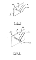
- Figure 3 shows a defined Abtropfstelle 14, which is preferably V-shaped. It can be seen from the perspective view of Figure 3 that below the V-shaped Abtropfstelle 14 a drip-16 is formed. It goes without saying that when the leakage water is between the two legs of the V-shape, it collects in the deepest and tends to flow out of the V-shape. To a so-called backflow To avoid the container 17, the resulting water is drained via the Abtropfnase 16 parallel at a distance from the container wall 17 derived.
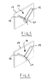
- FIG. 4 Another embodiment according to a defined Abtropfstelle 14 is also shown in Figure 4 in perspective, wherein the V-shape forming ribs 18 and 19 are converged or formed so that they include a recess 21 in the top of the V-shape , The recess 21, however, extends only in a partial region of the rib width in the region of the side remote from the container wall 17.
- an approach is formed, which protrudes beyond the lowest point of the Abtropfstelle 14.
- a flow direction is achieved, which is parallel to a distance from the container wall 17.
- the flow behavior of the water is also favored by the fact that the recess 21 in the tip of the converging ribs 18, 19 ensures that the draining water is always directed away to one of the ribs pointing vertically downwards. Due to the large forces at the lower edge of the attachment, the water gets a stronger component of movement to the side due to the adhesion forces, pointing away from the lower edge parallel to the container wall 17, as indicated by the flow arrows.
- FIG. 1 Another variant of a defined Abtropfstelle 14 according to the invention show the figures 5 and 6, wherein the figure 5 represent a in the top of the V-shaped extending ribs 18, 19 to the front notch 20. This results in a flow direction of the resulting water due to the opening angle of the notch 20, which is technological of the container wall 17.
- the notch 20 is embedded in a below the section line of the ribs 18, 19 formed neck.
- the running water gets a stronger component of movement forward.
- the inertia of the water then causes the water drips forward or expires.
- the tapered notch 20 separates the water further and further from the ribs 18, 19 as the contact surfaces become progressively smaller.
Landscapes
- Engineering & Computer Science (AREA)
- Textile Engineering (AREA)
- Detail Structures Of Washing Machines And Dryers (AREA)
- Detergent Compositions (AREA)
- Main Body Construction Of Washing Machines And Laundry Dryers (AREA)
- Motor Or Generator Frames (AREA)
Applications Claiming Priority (1)
| Application Number | Priority Date | Filing Date | Title |
|---|---|---|---|
| DE102004048556A DE102004048556B4 (de) | 2004-10-04 | 2004-10-04 | Laugenbehälter für eine Waschmaschine |
Publications (2)
| Publication Number | Publication Date |
|---|---|
| EP1643028A1 true EP1643028A1 (fr) | 2006-04-05 |
| EP1643028B1 EP1643028B1 (fr) | 2010-03-17 |
Family
ID=35511010
Family Applications (1)
| Application Number | Title | Priority Date | Filing Date |
|---|---|---|---|
| EP05020431A Expired - Lifetime EP1643028B1 (fr) | 2004-10-04 | 2005-09-20 | Cuve pour une machine à laver |
Country Status (5)
| Country | Link |
|---|---|
| US (1) | US7578151B2 (fr) |
| EP (1) | EP1643028B1 (fr) |
| AT (1) | ATE461310T1 (fr) |
| DE (2) | DE102004048556B4 (fr) |
| ES (1) | ES2341552T3 (fr) |
Cited By (2)
| Publication number | Priority date | Publication date | Assignee | Title |
|---|---|---|---|---|
| EP1829999A1 (fr) * | 2006-03-01 | 2007-09-05 | Miele & Cie. KG | Machine à laver avec une cuve dotée de moyens de vidange |
| ITMC20090027A1 (it) * | 2009-02-13 | 2010-08-14 | Meccanica Generale Srl | Vasca per macchina lavatrice o lavasciugatrice provvista di condotti. |
Families Citing this family (7)
| Publication number | Priority date | Publication date | Assignee | Title |
|---|---|---|---|---|
| DE102007044883A1 (de) * | 2007-09-20 | 2009-04-09 | BSH Bosch und Siemens Hausgeräte GmbH | Kunststoff-Laugenbehälter für eine Waschmaschine oder einen Waschtrockner |
| WO2009040302A1 (fr) * | 2007-09-20 | 2009-04-02 | BSH Bosch und Siemens Hausgeräte GmbH | Cuve en plastique pour un lave-linge ou un sèche-linge |
| DE102008016623B4 (de) * | 2008-04-01 | 2010-02-25 | BSH Bosch und Siemens Hausgeräte GmbH | Geschirrspülmaschine |
| USD707409S1 (en) * | 2012-04-09 | 2014-06-17 | Samsung Electronics Co., Ltd. | Tub for washing machine |
| DE102014113104A1 (de) * | 2014-09-11 | 2016-03-17 | Miele & Cie. Kg | Elastomerbauteil zum Verbinden von Gerätebauteilen eines elektrischen Geräts, elektrisches Gerät und Verwendung einer Abtropfrippe zum Ableiten von Fluid in einem elektrischen Gerät |
| US10988885B2 (en) * | 2018-12-28 | 2021-04-27 | Whirlpool Corporation | Extended tub for a laundry treating appliance |
| US12559877B2 (en) | 2021-08-30 | 2026-02-24 | Whirlpool Corporation | Structured geometry for a tub rear wall of a laundry appliance |
Citations (4)
| Publication number | Priority date | Publication date | Assignee | Title |
|---|---|---|---|---|
| JPH02305596A (ja) * | 1989-05-18 | 1990-12-19 | Toshiba Corp | 洗濯機 |
| GB2272913A (en) * | 1992-11-26 | 1994-06-01 | Caradon Rolinx | Tub for a top-loading washing machine |
| DE19960501A1 (de) * | 1999-12-15 | 2001-06-21 | Bsh Bosch Siemens Hausgeraete | Laugenbehälter für eine Waschmaschine |
| US20040148979A1 (en) * | 2002-11-28 | 2004-08-05 | No Yang Hwan | Washing machine |
Family Cites Families (11)
| Publication number | Priority date | Publication date | Assignee | Title |
|---|---|---|---|---|
| US3333282A (en) * | 1964-08-24 | 1967-08-01 | Mustee & Sons E L | Utility tubs |
| DE6752636U (de) | 1968-06-06 | 1969-03-27 | Siemens Electrogeraete | Federlager fuer die das trommelaggregat einer waschmaschine haltenden zugfedern. |
| JPS5488668A (en) | 1977-12-24 | 1979-07-13 | Matsushita Electric Ind Co Ltd | Single-tank washer |
| IT1136452B (it) * | 1980-07-03 | 1986-08-27 | Zanussi A Spa Industrie | Vasca in materia plastica per macchine lavabiancheria |
| JPS58261A (ja) | 1981-06-23 | 1983-01-05 | Matsushita Electric Ind Co Ltd | 洗濯機の脱水受筒支持装置 |
| AU632439B2 (en) * | 1989-10-05 | 1992-12-24 | Sanyo Electric Co., Ltd. | Drum-type washing machine |
| JPH04189397A (ja) | 1990-11-22 | 1992-07-07 | Matsushita Electric Ind Co Ltd | 電気洗濯機の防振装置 |
| JPH0768086A (ja) * | 1993-09-07 | 1995-03-14 | Mitsui Petrochem Ind Ltd | 洗濯機 |
| IT1289395B1 (it) * | 1996-10-08 | 1998-10-02 | Electrolux Zanussi Elettrodome | Procedimento perfezionato per lo stampaggio a iniezione di manufatti in materia plastica |
| GB2338543B (en) * | 1998-06-18 | 2002-08-07 | Gen Domestic Appliances Ltd | Washer dryer |
| JP3517618B2 (ja) * | 1999-10-21 | 2004-04-12 | 株式会社東芝 | ドラム式洗濯乾燥機 |
-
2004
- 2004-10-04 DE DE102004048556A patent/DE102004048556B4/de not_active Expired - Fee Related
-
2005
- 2005-09-20 AT AT05020431T patent/ATE461310T1/de not_active IP Right Cessation
- 2005-09-20 DE DE502005009223T patent/DE502005009223D1/de not_active Expired - Lifetime
- 2005-09-20 EP EP05020431A patent/EP1643028B1/fr not_active Expired - Lifetime
- 2005-09-20 ES ES05020431T patent/ES2341552T3/es not_active Expired - Lifetime
- 2005-10-04 US US11/243,049 patent/US7578151B2/en not_active Expired - Fee Related
Patent Citations (4)
| Publication number | Priority date | Publication date | Assignee | Title |
|---|---|---|---|---|
| JPH02305596A (ja) * | 1989-05-18 | 1990-12-19 | Toshiba Corp | 洗濯機 |
| GB2272913A (en) * | 1992-11-26 | 1994-06-01 | Caradon Rolinx | Tub for a top-loading washing machine |
| DE19960501A1 (de) * | 1999-12-15 | 2001-06-21 | Bsh Bosch Siemens Hausgeraete | Laugenbehälter für eine Waschmaschine |
| US20040148979A1 (en) * | 2002-11-28 | 2004-08-05 | No Yang Hwan | Washing machine |
Non-Patent Citations (1)
| Title |
|---|
| PATENT ABSTRACTS OF JAPAN vol. 015, no. 092 (C - 0811) 6 March 1991 (1991-03-06) * |
Cited By (3)
| Publication number | Priority date | Publication date | Assignee | Title |
|---|---|---|---|---|
| EP1829999A1 (fr) * | 2006-03-01 | 2007-09-05 | Miele & Cie. KG | Machine à laver avec une cuve dotée de moyens de vidange |
| ITMC20090027A1 (it) * | 2009-02-13 | 2010-08-14 | Meccanica Generale Srl | Vasca per macchina lavatrice o lavasciugatrice provvista di condotti. |
| EP2218816A1 (fr) * | 2009-02-13 | 2010-08-18 | Meccanica Generale S.R.L. | Cuve avec conduits pour une machine à laver ou à sécher |
Also Published As
| Publication number | Publication date |
|---|---|
| ES2341552T3 (es) | 2010-06-22 |
| EP1643028B1 (fr) | 2010-03-17 |
| ATE461310T1 (de) | 2010-04-15 |
| DE102004048556B4 (de) | 2008-06-05 |
| DE102004048556A1 (de) | 2006-04-20 |
| DE502005009223D1 (de) | 2010-04-29 |
| US7578151B2 (en) | 2009-08-25 |
| US20080060389A1 (en) | 2008-03-13 |
Similar Documents
| Publication | Publication Date | Title |
|---|---|---|
| EP3290572B1 (fr) | Appareil d'entretien de linge doté d'un dispositif formant conduite de dérivation | |
| DE102006003405B4 (de) | Waschmittelfach, Waschmittelfachanordnung und Waschmaschine mit denselben | |
| DE112007000013B4 (de) | Dampfgenerator und Waschmaschine mit einem solchen | |
| DE19856973B4 (de) | Fremdkörpersperre für Trommelwaschmaschinen | |
| DE112011101522B4 (de) | Wäschevorrichtung | |
| EP1643028B1 (fr) | Cuve pour une machine à laver | |
| DE10245217B4 (de) | Trommelwaschmaschine | |
| DE10237017B3 (de) | Wäschebehandlungsmaschine | |
| EP2478141B1 (fr) | Appareil électroménager véhiculant de l'eau équipé d'un dispositif d'alimentation en eau | |
| DE112006000038T5 (de) | Dampfgenerator für eine Trommelwaschmaschine | |
| EP2022882B1 (fr) | Tambour pour un lave-linge et lave-linge | |
| DE102006009057B4 (de) | Waschtrockner | |
| DE19961462B4 (de) | Haushaltgerät und Verfahren zu seinem Betreiben | |
| DE9112888U1 (de) | Luftzirkulationsleitung für Wäschetrocknermaschine | |
| DE102009028185A1 (de) | Wasserführendes Hausgerät mit einer Schale | |
| EP2388365A1 (fr) | Lave-linge à tambour | |
| DE102011053950A1 (de) | Waschmaschine mit einem in einem Maschinengehäuse angeordneten Laugenbehälter | |
| EP2647753A1 (fr) | Support de tube coudé pour supporter un flexible, agencement doté d'un tel support de tube coudé et appareil ménager fonctionnant avec de l'eau doté d'un tel agencement | |
| DE4435095C2 (de) | Waschmaschine mit einem kreisförmigen Laugenbehälter | |
| DE102008035790B4 (de) | Trommelwaschmaschine | |
| EP2460454B1 (fr) | Panneau pour un appareil ménager et appareil ménager | |
| DE10358941B3 (de) | Frontbeschickbare Waschmaschine | |
| EP1709231A2 (fr) | Lave-linge a chargement frontal, pourvu d'un tambour rotatif | |
| WO2008043707A1 (fr) | Appareil ménager avec un dispositif collecteur d'eau de fuite | |
| DE112005000124B4 (de) | Geschirrspülmaschine und zugehörige Ablaufschlauch-Befestigungsanordnung |
Legal Events
| Date | Code | Title | Description |
|---|---|---|---|
| PUAI | Public reference made under article 153(3) epc to a published international application that has entered the european phase |
Free format text: ORIGINAL CODE: 0009012 |
|
| AK | Designated contracting states |
Kind code of ref document: A1 Designated state(s): AT BE BG CH CY CZ DE DK EE ES FI FR GB GR HU IE IS IT LI LT LU LV MC NL PL PT RO SE SI SK TR |
|
| AX | Request for extension of the european patent |
Extension state: AL BA HR MK YU |
|
| 17P | Request for examination filed |
Effective date: 20060912 |
|
| AKX | Designation fees paid |
Designated state(s): AT BE BG CH CY CZ DE DK EE ES FI FR GB GR HU IE IS IT LI LT LU LV MC NL PL PT RO SE SI SK TR |
|
| GRAP | Despatch of communication of intention to grant a patent |
Free format text: ORIGINAL CODE: EPIDOSNIGR1 |
|
| GRAS | Grant fee paid |
Free format text: ORIGINAL CODE: EPIDOSNIGR3 |
|
| GRAA | (expected) grant |
Free format text: ORIGINAL CODE: 0009210 |
|
| AK | Designated contracting states |
Kind code of ref document: B1 Designated state(s): AT BE BG CH CY CZ DE DK EE ES FI FR GB GR HU IE IS IT LI LT LU LV MC NL PL PT RO SE SI SK TR |
|
| REG | Reference to a national code |
Ref country code: GB Ref legal event code: FG4D Free format text: NOT ENGLISH |
|
| REG | Reference to a national code |
Ref country code: CH Ref legal event code: EP |
|
| REG | Reference to a national code |
Ref country code: IE Ref legal event code: FG4D |
|
| REF | Corresponds to: |
Ref document number: 502005009223 Country of ref document: DE Date of ref document: 20100429 Kind code of ref document: P |
|
| REG | Reference to a national code |
Ref country code: GB Ref legal event code: 746 Effective date: 20100415 |
|
| REG | Reference to a national code |
Ref country code: ES Ref legal event code: FG2A Ref document number: 2341552 Country of ref document: ES Kind code of ref document: T3 |
|
| REG | Reference to a national code |
Ref country code: NL Ref legal event code: VDEP Effective date: 20100317 |
|
| PG25 | Lapsed in a contracting state [announced via postgrant information from national office to epo] |
Ref country code: LT Free format text: LAPSE BECAUSE OF FAILURE TO SUBMIT A TRANSLATION OF THE DESCRIPTION OR TO PAY THE FEE WITHIN THE PRESCRIBED TIME-LIMIT Effective date: 20100317 |
|
| LTIE | Lt: invalidation of european patent or patent extension |
Effective date: 20100317 |
|
| PG25 | Lapsed in a contracting state [announced via postgrant information from national office to epo] |
Ref country code: PL Free format text: LAPSE BECAUSE OF FAILURE TO SUBMIT A TRANSLATION OF THE DESCRIPTION OR TO PAY THE FEE WITHIN THE PRESCRIBED TIME-LIMIT Effective date: 20100317 Ref country code: SI Free format text: LAPSE BECAUSE OF FAILURE TO SUBMIT A TRANSLATION OF THE DESCRIPTION OR TO PAY THE FEE WITHIN THE PRESCRIBED TIME-LIMIT Effective date: 20100317 Ref country code: FI Free format text: LAPSE BECAUSE OF FAILURE TO SUBMIT A TRANSLATION OF THE DESCRIPTION OR TO PAY THE FEE WITHIN THE PRESCRIBED TIME-LIMIT Effective date: 20100317 Ref country code: LV Free format text: LAPSE BECAUSE OF FAILURE TO SUBMIT A TRANSLATION OF THE DESCRIPTION OR TO PAY THE FEE WITHIN THE PRESCRIBED TIME-LIMIT Effective date: 20100317 |
|
| REG | Reference to a national code |
Ref country code: IE Ref legal event code: FD4D |
|
| PG25 | Lapsed in a contracting state [announced via postgrant information from national office to epo] |
Ref country code: NL Free format text: LAPSE BECAUSE OF FAILURE TO SUBMIT A TRANSLATION OF THE DESCRIPTION OR TO PAY THE FEE WITHIN THE PRESCRIBED TIME-LIMIT Effective date: 20100317 Ref country code: SE Free format text: LAPSE BECAUSE OF FAILURE TO SUBMIT A TRANSLATION OF THE DESCRIPTION OR TO PAY THE FEE WITHIN THE PRESCRIBED TIME-LIMIT Effective date: 20100317 Ref country code: RO Free format text: LAPSE BECAUSE OF FAILURE TO SUBMIT A TRANSLATION OF THE DESCRIPTION OR TO PAY THE FEE WITHIN THE PRESCRIBED TIME-LIMIT Effective date: 20100317 Ref country code: GR Free format text: LAPSE BECAUSE OF FAILURE TO SUBMIT A TRANSLATION OF THE DESCRIPTION OR TO PAY THE FEE WITHIN THE PRESCRIBED TIME-LIMIT Effective date: 20100618 Ref country code: EE Free format text: LAPSE BECAUSE OF FAILURE TO SUBMIT A TRANSLATION OF THE DESCRIPTION OR TO PAY THE FEE WITHIN THE PRESCRIBED TIME-LIMIT Effective date: 20100317 Ref country code: CY Free format text: LAPSE BECAUSE OF FAILURE TO SUBMIT A TRANSLATION OF THE DESCRIPTION OR TO PAY THE FEE WITHIN THE PRESCRIBED TIME-LIMIT Effective date: 20100317 |
|
| PG25 | Lapsed in a contracting state [announced via postgrant information from national office to epo] |
Ref country code: SK Free format text: LAPSE BECAUSE OF FAILURE TO SUBMIT A TRANSLATION OF THE DESCRIPTION OR TO PAY THE FEE WITHIN THE PRESCRIBED TIME-LIMIT Effective date: 20100317 Ref country code: IS Free format text: LAPSE BECAUSE OF FAILURE TO SUBMIT A TRANSLATION OF THE DESCRIPTION OR TO PAY THE FEE WITHIN THE PRESCRIBED TIME-LIMIT Effective date: 20100717 Ref country code: CZ Free format text: LAPSE BECAUSE OF FAILURE TO SUBMIT A TRANSLATION OF THE DESCRIPTION OR TO PAY THE FEE WITHIN THE PRESCRIBED TIME-LIMIT Effective date: 20100317 Ref country code: BG Free format text: LAPSE BECAUSE OF FAILURE TO SUBMIT A TRANSLATION OF THE DESCRIPTION OR TO PAY THE FEE WITHIN THE PRESCRIBED TIME-LIMIT Effective date: 20100617 |
|
| PLBE | No opposition filed within time limit |
Free format text: ORIGINAL CODE: 0009261 |
|
| STAA | Information on the status of an ep patent application or granted ep patent |
Free format text: STATUS: NO OPPOSITION FILED WITHIN TIME LIMIT |
|
| PG25 | Lapsed in a contracting state [announced via postgrant information from national office to epo] |
Ref country code: PT Free format text: LAPSE BECAUSE OF FAILURE TO SUBMIT A TRANSLATION OF THE DESCRIPTION OR TO PAY THE FEE WITHIN THE PRESCRIBED TIME-LIMIT Effective date: 20100719 Ref country code: DK Free format text: LAPSE BECAUSE OF FAILURE TO SUBMIT A TRANSLATION OF THE DESCRIPTION OR TO PAY THE FEE WITHIN THE PRESCRIBED TIME-LIMIT Effective date: 20100317 Ref country code: IE Free format text: LAPSE BECAUSE OF FAILURE TO SUBMIT A TRANSLATION OF THE DESCRIPTION OR TO PAY THE FEE WITHIN THE PRESCRIBED TIME-LIMIT Effective date: 20100317 |
|
| 26N | No opposition filed |
Effective date: 20101220 |
|
| BERE | Be: lapsed |
Owner name: MIELE & CIE. K.G. Effective date: 20100930 |
|
| PG25 | Lapsed in a contracting state [announced via postgrant information from national office to epo] |
Ref country code: MC Free format text: LAPSE BECAUSE OF NON-PAYMENT OF DUE FEES Effective date: 20100930 |
|
| REG | Reference to a national code |
Ref country code: CH Ref legal event code: PL |
|
| PG25 | Lapsed in a contracting state [announced via postgrant information from national office to epo] |
Ref country code: CH Free format text: LAPSE BECAUSE OF NON-PAYMENT OF DUE FEES Effective date: 20100930 Ref country code: LI Free format text: LAPSE BECAUSE OF NON-PAYMENT OF DUE FEES Effective date: 20100930 Ref country code: BE Free format text: LAPSE BECAUSE OF NON-PAYMENT OF DUE FEES Effective date: 20100930 |
|
| PG25 | Lapsed in a contracting state [announced via postgrant information from national office to epo] |
Ref country code: AT Free format text: LAPSE BECAUSE OF NON-PAYMENT OF DUE FEES Effective date: 20100920 |
|
| PG25 | Lapsed in a contracting state [announced via postgrant information from national office to epo] |
Ref country code: HU Free format text: LAPSE BECAUSE OF FAILURE TO SUBMIT A TRANSLATION OF THE DESCRIPTION OR TO PAY THE FEE WITHIN THE PRESCRIBED TIME-LIMIT Effective date: 20100918 Ref country code: LU Free format text: LAPSE BECAUSE OF NON-PAYMENT OF DUE FEES Effective date: 20100920 |
|
| PG25 | Lapsed in a contracting state [announced via postgrant information from national office to epo] |
Ref country code: TR Free format text: LAPSE BECAUSE OF FAILURE TO SUBMIT A TRANSLATION OF THE DESCRIPTION OR TO PAY THE FEE WITHIN THE PRESCRIBED TIME-LIMIT Effective date: 20100317 |
|
| REG | Reference to a national code |
Ref country code: FR Ref legal event code: PLFP Year of fee payment: 12 |
|
| REG | Reference to a national code |
Ref country code: FR Ref legal event code: PLFP Year of fee payment: 13 |
|
| REG | Reference to a national code |
Ref country code: FR Ref legal event code: PLFP Year of fee payment: 14 |
|
| PGFP | Annual fee paid to national office [announced via postgrant information from national office to epo] |
Ref country code: FR Payment date: 20190926 Year of fee payment: 15 Ref country code: IT Payment date: 20190923 Year of fee payment: 15 |
|
| PGFP | Annual fee paid to national office [announced via postgrant information from national office to epo] |
Ref country code: GB Payment date: 20190930 Year of fee payment: 15 |
|
| PGFP | Annual fee paid to national office [announced via postgrant information from national office to epo] |
Ref country code: DE Payment date: 20190930 Year of fee payment: 15 |
|
| PGFP | Annual fee paid to national office [announced via postgrant information from national office to epo] |
Ref country code: ES Payment date: 20191021 Year of fee payment: 15 |
|
| REG | Reference to a national code |
Ref country code: DE Ref legal event code: R119 Ref document number: 502005009223 Country of ref document: DE |
|
| GBPC | Gb: european patent ceased through non-payment of renewal fee |
Effective date: 20200920 |
|
| PG25 | Lapsed in a contracting state [announced via postgrant information from national office to epo] |
Ref country code: DE Free format text: LAPSE BECAUSE OF NON-PAYMENT OF DUE FEES Effective date: 20210401 Ref country code: FR Free format text: LAPSE BECAUSE OF NON-PAYMENT OF DUE FEES Effective date: 20200930 |
|
| PG25 | Lapsed in a contracting state [announced via postgrant information from national office to epo] |
Ref country code: GB Free format text: LAPSE BECAUSE OF NON-PAYMENT OF DUE FEES Effective date: 20200920 |
|
| REG | Reference to a national code |
Ref country code: ES Ref legal event code: FD2A Effective date: 20220118 |
|
| PG25 | Lapsed in a contracting state [announced via postgrant information from national office to epo] |
Ref country code: IT Free format text: LAPSE BECAUSE OF NON-PAYMENT OF DUE FEES Effective date: 20200920 |
|
| PG25 | Lapsed in a contracting state [announced via postgrant information from national office to epo] |
Ref country code: ES Free format text: LAPSE BECAUSE OF NON-PAYMENT OF DUE FEES Effective date: 20200921 |