EP1643084A1 - Mantelringsegment eines Turbinetriebwerks und Aufhängevorrichtung - Google Patents
Mantelringsegment eines Turbinetriebwerks und Aufhängevorrichtung Download PDFInfo
- Publication number
- EP1643084A1 EP1643084A1 EP05252173A EP05252173A EP1643084A1 EP 1643084 A1 EP1643084 A1 EP 1643084A1 EP 05252173 A EP05252173 A EP 05252173A EP 05252173 A EP05252173 A EP 05252173A EP 1643084 A1 EP1643084 A1 EP 1643084A1
- Authority
- EP
- European Patent Office
- Prior art keywords
- segment
- hanger
- shroud
- projection
- spaced apart
- Prior art date
- Legal status (The legal status is an assumption and is not a legal conclusion. Google has not performed a legal analysis and makes no representation as to the accuracy of the status listed.)
- Granted
Links
- 239000000463 material Substances 0.000 claims description 26
- 239000012530 fluid Substances 0.000 claims description 8
- 239000011153 ceramic matrix composite Substances 0.000 description 14
- 238000001816 cooling Methods 0.000 description 6
- 239000000919 ceramic Substances 0.000 description 5
- 239000000835 fiber Substances 0.000 description 4
- 238000007789 sealing Methods 0.000 description 4
- 239000011159 matrix material Substances 0.000 description 2
- 229910001092 metal group alloy Inorganic materials 0.000 description 2
- 241000192308 Agrostis hyemalis Species 0.000 description 1
- 230000000712 assembly Effects 0.000 description 1
- 238000000429 assembly Methods 0.000 description 1
- 238000005452 bending Methods 0.000 description 1
- 238000002485 combustion reaction Methods 0.000 description 1
- 238000004891 communication Methods 0.000 description 1
- 230000003247 decreasing effect Effects 0.000 description 1
- 239000000284 extract Substances 0.000 description 1
- 238000004519 manufacturing process Methods 0.000 description 1
- 239000007769 metal material Substances 0.000 description 1
- 230000000452 restraining effect Effects 0.000 description 1
- 230000000630 rising effect Effects 0.000 description 1
Images



Classifications
-
- F—MECHANICAL ENGINEERING; LIGHTING; HEATING; WEAPONS; BLASTING
- F02—COMBUSTION ENGINES; HOT-GAS OR COMBUSTION-PRODUCT ENGINE PLANTS
- F02C—GAS-TURBINE PLANTS; AIR INTAKES FOR JET-PROPULSION PLANTS; CONTROLLING FUEL SUPPLY IN AIR-BREATHING JET-PROPULSION PLANTS
- F02C7/00—Features, components parts, details or accessories, not provided for in, or of interest apart form groups F02C1/00 - F02C6/00; Air intakes for jet-propulsion plants
- F02C7/24—Heat or noise insulation
-
- F—MECHANICAL ENGINEERING; LIGHTING; HEATING; WEAPONS; BLASTING
- F01—MACHINES OR ENGINES IN GENERAL; ENGINE PLANTS IN GENERAL; STEAM ENGINES
- F01D—NON-POSITIVE DISPLACEMENT MACHINES OR ENGINES, e.g. STEAM TURBINES
- F01D25/00—Component parts, details, or accessories, not provided for in, or of interest apart from, other groups
- F01D25/24—Casings; Casing parts, e.g. diaphragms, casing fastenings
- F01D25/246—Fastening of diaphragms or stator-rings
-
- F—MECHANICAL ENGINEERING; LIGHTING; HEATING; WEAPONS; BLASTING
- F01—MACHINES OR ENGINES IN GENERAL; ENGINE PLANTS IN GENERAL; STEAM ENGINES
- F01D—NON-POSITIVE DISPLACEMENT MACHINES OR ENGINES, e.g. STEAM TURBINES
- F01D9/00—Stators
- F01D9/02—Nozzles; Nozzle boxes; Stator blades; Guide conduits, e.g. individual nozzles
- F01D9/04—Nozzles; Nozzle boxes; Stator blades; Guide conduits, e.g. individual nozzles forming ring or sector
Definitions
- This invention relates generally to turbine engine shroud segments, segment hangers, and shroud assemblies including a surface exposed to elevated temperature engine gas flow. More particularly, it relates to gas turbine engine shroud segments, for example used in the turbine section of a gas turbine engine, and made of a low ductility material.
- a plurality of gas turbine engine stationary shroud segments are assembled circumferentially about an axial flow engine axis and about, typically radially outwardly of, rotating blading members, for example about turbine blades. Such assembly of shroud segments defines a part of the radial outer flowpath boundary over the blades. As has been described in various forms in the gas turbine engine art, it is desirable to maintain the operating clearance between the tips of the rotating blades and the cooperating, juxtaposed surface of the stationary shroud segments as close as possible to enhance engine operating efficiency.
- Typical examples of printed material relating to turbine engine shrouds and such shroud clearance include U.S Patents 5,071,313 - Nichols; 5,074,748 - Hagle; 5,127,793 - Walker et al.; and 5,562,408 - Proctor et al.; and U.S. Patent Application Publications 2003/0133790 A1 - Darkins, Jr. et al, and 2003/0185674 A1 ⁇ Alford et al.
- the shroud segment In its function as a flowpath component, the shroud segment, carried in an assembly with the shroud hanger, must be capable of meeting the design life requirements selected for use in a designed engine operating temperature and pressure environment. To enable current materials to operate effectively as shroud segments in the strenuous temperature and pressure conditions as exist in the turbine section flowpath of modern gas turbine engines, it has been a practice to provide cooling air to a portion of the shroud segment away from the engine flowpath. Examples of typical cooling arrangements are described in some of the above-identified patents.
- shroud segments in a gas turbine engine shroud assembly about rotating blades are arced circumferentially to define a flowpath annular surface about the rotating tips of the blades.
- annular surface is the sealing surface for the turbine blade tips.
- One condition is the application of cooling air to the outer portion of a shroud segment, creating in the shroud segment a thermal gradient or differential between the inner shroud surface exposed to a relatively high operating gas flow temperature and the cooled outer surface.
- thermal gradient is a form of shroud segment deformation or deflection generally referred to as "chording".
- At least the radially inner or flowpath surface of a shroud and its segments are arced circumferentially to define a flowpath annular surface about the rotating tips of the blades.
- the thermal gradient between the inner and outer faces of the shroud, resulting from cooling air impingement on the outer surface causes the arc of the shroud segments to chord or tend to straighten out circumferentially.
- chording the circumferential end portions of the inner surface of the shroud segment tend to move radially outwardly in respect to the middle portion of the segment.
- Metallic type materials currently and typically used as shrouds and shroud segments have mechanical properties including strength and ductility sufficiently high to enable the shrouds to be restrained against such deflection or distortion resulting from thermal gradients and pressure differential forces.
- Examples of such restraint include the well known side rail type of structure, or the C-clip type of sealing structure, for example described in the above identified Walker et al patent. That kind of restraint and sealing results in application of a compressive force at least to one end of the shroud to inhibit chording or other distortion.
- CMC ceramic matrix composite
- CMC type materials have relatively low tensile ductility or low strain to failure when compared with metallic materials.
- CMC type materials have a coefficient of thermal expansion (CTE) in the range of about 1.5-5 microinch/inch/°F, significantly different from commercial metal alloys used as restraining supports or hangers for metallic shrouds and desired to be used with CMC materials.
- Such metal alloys typically have a CTE in the range of about 7-10 microinch/inch/°F. Therefore, if a CMC type of shroud segment is restrained and cooled on one surface during operation, forces can be developed in CMC type segment sufficient to cause failure of the segment.
- CMC materials include a ceramic type fiber for example SiC, forms of which are coated with a compliant material such as BN. The fibers are carried in a ceramic type matrix, one form of which is SiC.
- CMC type materials have a room temperature tensile ductility of no greater than about 1%, herein used to define and mean a low tensile ductility material.
- CMC type materials have a room temperature tensile ductility in the range of about 0.4 - 0.7%. This is compared with metallic shroud and/or supporting structure or hanger materials having a room temperature tensile ductility of at least about 5%, for example in the range of about 5 - 15%.
- Shroud segments made from CMC type materials although having certain higher temperature capabilities than those of a metallic type material, cannot tolerate the above described and currently used type of compressive force or similar restraint force against chording and other deflection or distortion. Neither can they withstand a stress rising type of feature, for example one provided at a relatively small bent or filleted surface area, without sustaining damage or fracture typically experienced by ceramic type materials. Furthermore, manufacture of articles from CMC materials limits the bending of the SiC fibers about such a relatively tight fillet to avoid fracture of the relatively brittle ceramic type fibers in the ceramic matrix.
- a form of the present invention is a turbine engine shroud segment, for example for use in a turbine engine shroud assembly with a shroud hanger, comprising a shroud segment body including spaced apart inner and outer surfaces between spaced apart segment body first and second axial and first and second circumferential edge portions.
- the shroud segment includes a shroud segment projection integral with and extending in a direction away from the segment body outer surface.
- the shroud segment projection extends axially along at least a portion of the shroud segment body outer surface between the segment body first and second axial edge portions and spaced apart from the segment body first and second circumferential edge portions.
- the shroud segment projection comprises at least first and second circumferentially spaced apart shroud segment support surfaces of selected support surface shape and facing toward the segment body outer surface.
- the first shroud segment support surface faces toward the segment body first circumferential edge portion and the second shroud segment support surface faces toward the segment body second circumferential edge portion opposed to the first shroud segment support surface.
- the hanger comprises a hanger body including spaced apart hanger body inner and outer surfaces between spaced apart hanger body first and second axial edge portions and first and second circumferential edge portions.
- the hanger includes a hanger projection that extends axially along at least a portion of the hanger body inner surface between the hanger body axial edge portions, spaced apart from the hanger body circumferential edge portions.
- the hanger projection comprises at least first and second circumferentially spaced apart hanger bearing surfaces of selected bearing surface shape and facing respectively toward the hanger body first and second circumferential edge portions, for registry with and support of a pair of circumferentially adjacent shroud segments at respective cooperating shroud segment support surfaces.
- the hanger first bearing surface faces the hanger body first circumferential edge portion and the hanger second bearing surface faces the hanger body second circumferential edge portion opposed to the first hanger bearing surface.
- Still another form of the present invention is a turbine engine shroud assembly comprising a plurality of shroud segments and shroud segment hangers.
- Such shroud segment hangers are assembled about the shroud segments, a shroud segment hanger being between a pair of adjacent shroud segments with its hanger projection axially along and in juxtaposition with an axial interface between the pair of adjacent shroud segments.
- Each shroud hanger is assembled in registry with the pair of adjacent shroud segments through cooperating respective shroud segment support surfaces and shroud hanger bearing surfaces.
- Such an engine comprises, in serial flow communication generally from forward to aft, one or more compressors, a combustion section, and one or more turbine sections disposed axisymmetrically about a longitudinal engine axis.
- phrases using the term “axially”, for example “axially forward” and “axially aft”, refer to relative positions or directions in respect to the engine axis; phrases using forms of the term “circumferential” refer to circumferential position or direction generally about the engine axis; and phrases using forms of the term “radial”, for example “radially inner” and “radially outer”, refer to relative radial position or direction generally from the engine axis.
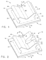
- FIGS 1, 2, 3, 4 and 5 are pictorial-type diagrammatic perspective views of embodiments of a turbine engine shroud segment according to forms of the present invention.
- Such embodiments enable carrying of a shroud segment, made of the above described low ductility materials such as a CMC, in a turbine engine shroud assembly without application of excessive pressure or force to the shroud segment.
- a shroud segment shown generally at 10 includes a shroud segment body, shown generally at 12, having a segment body radially inner surface 14 and a segment body radially outer surface 16 spaced apart from radially inner surface 14.
- Body 12 extends between spaced apart first and second axial edge portions, respectively 18 and 20, and first and second circumferential edge portions, respectively 22 and 24.
- shroud segment 10 includes a shroud segment projection 26, Figure 1, integral with and extending in a radially outward direction, meaning predominantly radially outward, from shroud body radially outer surface 16.
- Shroud segment projection 26 comprises at least first and second circumferentially spaced apart shroud segment support surfaces, respectively 28 and 30, of a selected shape, for example substantially planar, and facing toward segment body radially outer surface 16.
- the terms "toward” or “away from” in respect to a surface direction means generally and predominantly in the direction with respect to such surface or member.
- a segment support surface 28 is shown more clearly in Figure 5.
- Shroud segment first support surface 28 faces toward segment body first circumferential edge portion 22, and shroud segment second support surface 30 faces toward segment body second circumferential edge portion 24 in opposition to shroud segment first support surface 28.
- shroud projection 26 is shown generally at 38 as a projection array.
- shroud projection array 38 includes at least three projection hooks 40, 42 and 44; in Figures 4 and 5, projection array 38 includes four projection hooks 40, 42, 44 and 46.
- Projection hook 40, and projection hook 46 in the embodiments of Figures 4 and 5, represent a first pair of projection hooks facing toward first circumferential edge portion 22 and including first shroud segment support surfaces 28 facing radially inwardly toward segment body radially outer surface 16.
- Projection hooks 42 and 44 represent a second pair of projection hooks facing toward second circumferential edge portion 24, in circumferential opposition to projection hooks 40 and 46, and including second shroud segment support surfaces 30 facing radially inwardly toward segment body radially outer surface 16. Each such projection hook is integral with and extends generally radially away from segment body radially outer surface 16.
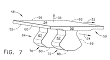
- FIGS 6 and 7 are diagrammatic perspective views of embodiments of a turbine engine shroud segment hanger shown generally at 48 according to forms of the present invention.
- Shroud segment hanger 48 can cooperate in a turbine engine shroud assembly to support the above described turbine engine shroud segment without application of excessive force to the shroud segment.
- Shroud segment hanger 48 comprises a hanger body shown generally at 50, including hanger body radially inner surface 52 and hanger body radially outer surface 54 spaced apart from hanger body radially inner surface 52.
- Hanger body 50 extends between spaced apart hanger body first and second axial edge portions, respectively 56 and 58, and first and second circumferential edge portions, respectively 60 and 62.
- Hanger 48 includes a hanger projection, shown generally at 64, extending axially along at least a portion of hanger radially inner surface 52 between hanger body axial edge portions 56 and 58, spaced apart from hanger body circumferential edge portions 60 and 62.
- hanger projection 64 is positioned axially between hanger body axial edge portions 56 and 58 along a midway portion of hanger body radially inner surface 52, spaced apart from hanger body circumferential edge portions 60 and 62 and conveniently integral with hanger body 50.
- Hanger projection 64 shown in an axially segmented embodiment in Figure 7, comprises at least first and second circumferentially spaced apart and opposed hanger bearing surfaces, respectively 66 and 68, of hanger projection 64 in Figure 6, and hanger first and second bearing surface portions, respectively 67 and 69, of hanger projection segments 70 and 72 in Figure 7.
- the hanger bearing surfaces and hanger bearing surface portions are of a selected surface shape matched for cooperating area registry with a selected shroud segment support surface shape. Conveniently such selected shape is planar as shown in more detail in phantom for hanger bearing surface 66 in Figure 6 and hanger first bearing surface portion 67 in Figure 7.
- hanger projection 64 can be provided in a number of hanger projection segments 70 and 72, as in Figure 7, for support of a corresponding number of cooperating shroud segment projection hooks.
- One example is support of hooks 40 and 46, or hooks 42 and 44, in shroud segment projection array 38 in Figures 4 and 5 as described above.
- Hanger bearing surfaces 66 and 68, and hanger bearing surface segments 67 and 69 face generally radially outwardly, respectively generally toward hanger first and second hanger body circumferential edge portions 60 and 62.
- FIG. 8 An example of a turbine engine shroud assembly is shown in the diagrammatic fragmentary partially sectional axial view of Figure 8.
- a plurality of shroud segments 10, for example shroud segments as in Figure 1 is assembled circumferentially; and a plurality of shroud segment hangers 48, for example shroud hangers as in Figure 6, is assembled circumferentially, radially outwardly about and supporting the shroud segments.
- Each shroud segment hanger 48, radially outwardly of shroud segments 10 is assembled with a hanger projection 64 between a pair of adjacent shroud segments 10 axially along and in juxtaposition with, in this example radially away from, an axial interface or gap 74 between adjacent shroud segments 10.
- Hanger bearing surfaces 66 and 68 are for registry with and support of a pair of circumferentially adjacent shroud segments 10 at respective cooperating shroud segment support surfaces 28 and 30.
- hanger bearing surface 66 is in registry with and carries cooperating segment support surface 30
- hanger bearing surface 68 is in registry with and carries cooperating segment support surface 28.
- fluid seal 76 is provided radially outwardly of interface 74, for example carried in recess 78 of hanger projection radially inner surface 80.
- Fluid seal 76 one form of which is a metallic bar seal of a type frequently used in turbine engines, is provided to inhibit radially outward flow or leakage of fluid from a turbine engine flowpath.
- hanger support 82 through which hanger 48 is carried by typical turbine engine structure (not shown).
Landscapes
- Engineering & Computer Science (AREA)
- Chemical & Material Sciences (AREA)
- Combustion & Propulsion (AREA)
- Mechanical Engineering (AREA)
- General Engineering & Computer Science (AREA)
- Turbine Rotor Nozzle Sealing (AREA)
Applications Claiming Priority (1)
| Application Number | Priority Date | Filing Date | Title |
|---|---|---|---|
| US10/863,434 US7052235B2 (en) | 2004-06-08 | 2004-06-08 | Turbine engine shroud segment, hanger and assembly |
Publications (2)
| Publication Number | Publication Date |
|---|---|
| EP1643084A1 true EP1643084A1 (de) | 2006-04-05 |
| EP1643084B1 EP1643084B1 (de) | 2007-12-19 |
Family
ID=35106849
Family Applications (1)
| Application Number | Title | Priority Date | Filing Date |
|---|---|---|---|
| EP05252173A Expired - Lifetime EP1643084B1 (de) | 2004-06-08 | 2005-04-07 | Mantelringsegment eines Turbinentriebwerks und Aufhängevorrichtung |
Country Status (5)
| Country | Link |
|---|---|
| US (1) | US7052235B2 (de) |
| EP (1) | EP1643084B1 (de) |
| JP (1) | JP2005351265A (de) |
| CA (1) | CA2502805A1 (de) |
| DE (1) | DE602005003891T2 (de) |
Cited By (4)
| Publication number | Priority date | Publication date | Assignee | Title |
|---|---|---|---|---|
| GB2480766A (en) * | 2010-05-28 | 2011-11-30 | Gen Electric | Turbine shroud |
| EP2924246A1 (de) * | 2014-03-27 | 2015-09-30 | Rolls-Royce plc | Auskleidungsanordnung |
| US10072572B2 (en) | 2014-04-09 | 2018-09-11 | Rolls-Royce Plc | Gas turbine engine |
| US10100659B2 (en) | 2014-12-16 | 2018-10-16 | Rolls-Royce North American Technologies Inc. | Hanger system for a turbine engine component |
Families Citing this family (63)
| Publication number | Priority date | Publication date | Assignee | Title |
|---|---|---|---|---|
| US7387758B2 (en) * | 2005-02-16 | 2008-06-17 | Siemens Power Generation, Inc. | Tabbed ceramic article for improved interlaminar strength |
| US9039358B2 (en) * | 2007-01-03 | 2015-05-26 | United Technologies Corporation | Replaceable blade outer air seal design |
| US7811054B2 (en) * | 2007-05-30 | 2010-10-12 | General Electric Company | Shroud configuration having sloped seal |
| US20090053045A1 (en) * | 2007-08-22 | 2009-02-26 | General Electric Company | Turbine Shroud for Gas Turbine Assemblies and Processes for Forming the Shroud |
| US9297335B2 (en) * | 2008-03-11 | 2016-03-29 | United Technologies Corporation | Metal injection molding attachment hanger system for a cooling liner within a gas turbine engine swivel exhaust duct |
| US8206087B2 (en) * | 2008-04-11 | 2012-06-26 | Siemens Energy, Inc. | Sealing arrangement for turbine engine having ceramic components |
| US8147192B2 (en) * | 2008-09-19 | 2012-04-03 | General Electric Company | Dual stage turbine shroud |
| US8985944B2 (en) * | 2011-03-30 | 2015-03-24 | General Electric Company | Continuous ring composite turbine shroud |
| US9726043B2 (en) | 2011-12-15 | 2017-08-08 | General Electric Company | Mounting apparatus for low-ductility turbine shroud |
| WO2013102171A2 (en) | 2011-12-31 | 2013-07-04 | Rolls-Royce Corporation | Blade track assembly, components, and methods |
| CN105074138B (zh) * | 2013-02-25 | 2017-03-29 | 通用电气公司 | 整体分段式cmc护罩悬挂器和保持器系统 |
| WO2014158286A1 (en) * | 2013-03-12 | 2014-10-02 | Thomas David J | Turbine blade track assembly |
| US9458726B2 (en) | 2013-03-13 | 2016-10-04 | Rolls-Royce Corporation | Dovetail retention system for blade tracks |
| US9506356B2 (en) * | 2013-03-15 | 2016-11-29 | Rolls-Royce North American Technologies, Inc. | Composite retention feature |
| CA2912428C (en) | 2013-05-17 | 2018-03-13 | General Electric Company | Cmc shroud support system of a gas turbine |
| WO2015038341A1 (en) * | 2013-09-11 | 2015-03-19 | United Technologies Corporation | Blade outer air seal having angled retention hook |
| WO2015069358A2 (en) | 2013-09-11 | 2015-05-14 | United Technologies Corporation | Ceramic liner for a turbine exhaust case |
| EP3080403B1 (de) | 2013-12-12 | 2019-05-01 | General Electric Company | Trägersystem für cmc-mantel |
| CA2951638A1 (en) | 2014-06-12 | 2015-12-17 | General Electric Company | Shroud hanger assembly |
| CA2951425C (en) | 2014-06-12 | 2019-12-24 | General Electric Company | Shroud hanger assembly |
| EP3155229B1 (de) * | 2014-06-12 | 2020-03-18 | General Electric Company | Ummantelungsaufhängeranordnung |
| CN106460543B (zh) | 2014-06-12 | 2018-12-21 | 通用电气公司 | 多件式护罩悬挂器组件 |
| US10934871B2 (en) * | 2015-02-20 | 2021-03-02 | Rolls-Royce North American Technologies Inc. | Segmented turbine shroud with sealing features |
| US9874104B2 (en) | 2015-02-27 | 2018-01-23 | General Electric Company | Method and system for a ceramic matrix composite shroud hanger assembly |
| US10215056B2 (en) | 2015-06-30 | 2019-02-26 | Rolls-Royce Corporation | Turbine shroud with movable attachment features |
| US10030541B2 (en) | 2015-07-01 | 2018-07-24 | Rolls-Royce North American Technologies Inc. | Turbine shroud with clamped flange attachment |
| US10767863B2 (en) | 2015-07-22 | 2020-09-08 | Rolls-Royce North American Technologies, Inc. | Combustor tile with monolithic inserts |
| US10107129B2 (en) | 2016-03-16 | 2018-10-23 | United Technologies Corporation | Blade outer air seal with spring centering |
| US10132184B2 (en) | 2016-03-16 | 2018-11-20 | United Technologies Corporation | Boas spring loaded rail shield |
| US10422241B2 (en) | 2016-03-16 | 2019-09-24 | United Technologies Corporation | Blade outer air seal support for a gas turbine engine |
| US10513943B2 (en) | 2016-03-16 | 2019-12-24 | United Technologies Corporation | Boas enhanced heat transfer surface |
| US10443616B2 (en) * | 2016-03-16 | 2019-10-15 | United Technologies Corporation | Blade outer air seal with centrally mounted seal arc segments |
| US10161258B2 (en) | 2016-03-16 | 2018-12-25 | United Technologies Corporation | Boas rail shield |
| US10337346B2 (en) | 2016-03-16 | 2019-07-02 | United Technologies Corporation | Blade outer air seal with flow guide manifold |
| US10138750B2 (en) | 2016-03-16 | 2018-11-27 | United Technologies Corporation | Boas segmented heat shield |
| US10563531B2 (en) * | 2016-03-16 | 2020-02-18 | United Technologies Corporation | Seal assembly for gas turbine engine |
| US10422240B2 (en) | 2016-03-16 | 2019-09-24 | United Technologies Corporation | Turbine engine blade outer air seal with load-transmitting cover plate |
| US10415414B2 (en) | 2016-03-16 | 2019-09-17 | United Technologies Corporation | Seal arc segment with anti-rotation feature |
| US10443424B2 (en) | 2016-03-16 | 2019-10-15 | United Technologies Corporation | Turbine engine blade outer air seal with load-transmitting carriage |
| US10138749B2 (en) | 2016-03-16 | 2018-11-27 | United Technologies Corporation | Seal anti-rotation feature |
| US20170276000A1 (en) * | 2016-03-24 | 2017-09-28 | General Electric Company | Apparatus and method for forming apparatus |
| US10196918B2 (en) * | 2016-06-07 | 2019-02-05 | United Technologies Corporation | Blade outer air seal made of ceramic matrix composite |
| US10577970B2 (en) | 2016-09-13 | 2020-03-03 | Rolls-Royce North American Technologies Inc. | Turbine assembly with ceramic matrix composite blade track and actively cooled metallic carrier |
| US10697314B2 (en) | 2016-10-14 | 2020-06-30 | Rolls-Royce Corporation | Turbine shroud with I-beam construction |
| US10577951B2 (en) | 2016-11-30 | 2020-03-03 | Rolls-Royce North American Technologies Inc. | Gas turbine engine with dovetail connection having contoured root |
| US10557365B2 (en) | 2017-10-05 | 2020-02-11 | Rolls-Royce Corporation | Ceramic matrix composite blade track with mounting system having reaction load distribution features |
| US11111806B2 (en) * | 2018-08-06 | 2021-09-07 | Raytheon Technologies Corporation | Blade outer air seal with circumferential hook assembly |
| US11131204B2 (en) | 2018-08-21 | 2021-09-28 | General Electric Company | Additively manufactured nested segment assemblies for turbine engines |
| US11286801B2 (en) | 2018-10-12 | 2022-03-29 | Raytheon Technologies Corporation | Boas with twin axial dovetail |
| US11098608B2 (en) | 2019-03-13 | 2021-08-24 | Raytheon Technologies Corporation | CMC BOAS with internal support structure |
| US11761343B2 (en) * | 2019-03-13 | 2023-09-19 | Rtx Corporation | BOAS carrier with dovetail attachments |
| US10989059B2 (en) | 2019-04-10 | 2021-04-27 | Raytheon Technologies Corporation | CMC BOAS arrangement |
| US11125096B2 (en) * | 2019-05-03 | 2021-09-21 | Raytheon Technologies Corporation | CMC boas arrangement |
| US11105214B2 (en) | 2019-07-19 | 2021-08-31 | Raytheon Technologies Corporation | CMC BOAS arrangement |
| US11073037B2 (en) * | 2019-07-19 | 2021-07-27 | Raytheon Technologies Corporation | CMC BOAS arrangement |
| US11073038B2 (en) | 2019-07-19 | 2021-07-27 | Raytheon Technologies Corporation | CMC BOAS arrangement |
| US11248482B2 (en) | 2019-07-19 | 2022-02-15 | Raytheon Technologies Corporation | CMC BOAS arrangement |
| US11149563B2 (en) | 2019-10-04 | 2021-10-19 | Rolls-Royce Corporation | Ceramic matrix composite blade track with mounting system having axial reaction load distribution features |
| US11125099B2 (en) * | 2019-11-06 | 2021-09-21 | Raytheon Technologies Corporation | Boas arrangement with double dovetail attachments |
| US11319822B2 (en) | 2020-05-06 | 2022-05-03 | Rolls-Royce North American Technologies Inc. | Hybrid vane segment with ceramic matrix composite airfoils |
| US11111796B1 (en) | 2020-05-18 | 2021-09-07 | Rolls-Royce North American Technologies Inc. | Turbine shroud assembly with dovetail retention system |
| US11230937B2 (en) * | 2020-05-18 | 2022-01-25 | Rolls-Royce North American Technologies Inc. | Turbine shroud assembly with dovetail retention system |
| US11873762B2 (en) | 2020-06-16 | 2024-01-16 | Rolls-Royce Corporation | High temperature heat shield assemblies |
Citations (5)
| Publication number | Priority date | Publication date | Assignee | Title |
|---|---|---|---|---|
| US5127793A (en) * | 1990-05-31 | 1992-07-07 | General Electric Company | Turbine shroud clearance control assembly |
| US6602050B1 (en) * | 1999-03-24 | 2003-08-05 | Siemens Aktiengesellschaft | Covering element and arrangement with a covering element and a support structure |
| EP1350927A2 (de) * | 2002-03-28 | 2003-10-08 | General Electric Company | Mantelringsegment, Herstellungsverfahren eines Mantelringsegments, sowie Mantelringanordnung für ein Turbinentriebwerk |
| US20040005216A1 (en) * | 2002-07-02 | 2004-01-08 | Ishikawajima-Harima Heavy Industries Co., Ltd. | Gas turbine shroud structure |
| US20040062639A1 (en) * | 2002-09-30 | 2004-04-01 | Glynn Christopher Charles | Turbine engine shroud assembly including axially floating shroud segment |
Family Cites Families (15)
| Publication number | Priority date | Publication date | Assignee | Title |
|---|---|---|---|---|
| US3085398A (en) * | 1961-01-10 | 1963-04-16 | Gen Electric | Variable-clearance shroud structure for gas turbine engines |
| FR2143561B1 (de) * | 1971-06-29 | 1974-03-08 | Snecma | |
| US3807891A (en) * | 1972-09-15 | 1974-04-30 | United Aircraft Corp | Thermal response turbine shroud |
| GB1484936A (en) * | 1974-12-07 | 1977-09-08 | Rolls Royce | Gas turbine engines |
| US3966353A (en) * | 1975-02-21 | 1976-06-29 | Westinghouse Electric Corporation | Ceramic-to-metal (or ceramic) cushion/seal for use with three piece ceramic stationary vane assembly |
| JPS59222566A (ja) * | 1983-05-30 | 1984-12-14 | Kawasaki Heavy Ind Ltd | 耐熱構造体の製造方法 |
| US5071313A (en) * | 1990-01-16 | 1991-12-10 | General Electric Company | Rotor blade shroud segment |
| US5228828A (en) * | 1991-02-15 | 1993-07-20 | General Electric Company | Gas turbine engine clearance control apparatus |
| US5441385A (en) * | 1993-12-13 | 1995-08-15 | Solar Turbines Incorporated | Turbine nozzle/nozzle support structure |
| US5480281A (en) * | 1994-06-30 | 1996-01-02 | General Electric Co. | Impingement cooling apparatus for turbine shrouds having ducts of increasing cross-sectional area in the direction of post-impingement cooling flow |
| US5562408A (en) * | 1995-06-06 | 1996-10-08 | General Electric Company | Isolated turbine shroud |
| US6315519B1 (en) * | 1998-09-28 | 2001-11-13 | General Electric Company | Turbine inner shroud and turbine assembly containing such inner shroud |
| US6435824B1 (en) * | 2000-11-08 | 2002-08-20 | General Electric Co. | Gas turbine stationary shroud made of a ceramic foam material, and its preparation |
| US6702550B2 (en) * | 2002-01-16 | 2004-03-09 | General Electric Company | Turbine shroud segment and shroud assembly |
| US6821085B2 (en) * | 2002-09-30 | 2004-11-23 | General Electric Company | Turbine engine axially sealing assembly including an axially floating shroud, and assembly method |
-
2004
- 2004-06-08 US US10/863,434 patent/US7052235B2/en not_active Expired - Fee Related
-
2005
- 2005-03-31 CA CA002502805A patent/CA2502805A1/en not_active Abandoned
- 2005-04-07 JP JP2005110429A patent/JP2005351265A/ja active Pending
- 2005-04-07 DE DE602005003891T patent/DE602005003891T2/de not_active Expired - Lifetime
- 2005-04-07 EP EP05252173A patent/EP1643084B1/de not_active Expired - Lifetime
Patent Citations (5)
| Publication number | Priority date | Publication date | Assignee | Title |
|---|---|---|---|---|
| US5127793A (en) * | 1990-05-31 | 1992-07-07 | General Electric Company | Turbine shroud clearance control assembly |
| US6602050B1 (en) * | 1999-03-24 | 2003-08-05 | Siemens Aktiengesellschaft | Covering element and arrangement with a covering element and a support structure |
| EP1350927A2 (de) * | 2002-03-28 | 2003-10-08 | General Electric Company | Mantelringsegment, Herstellungsverfahren eines Mantelringsegments, sowie Mantelringanordnung für ein Turbinentriebwerk |
| US20040005216A1 (en) * | 2002-07-02 | 2004-01-08 | Ishikawajima-Harima Heavy Industries Co., Ltd. | Gas turbine shroud structure |
| US20040062639A1 (en) * | 2002-09-30 | 2004-04-01 | Glynn Christopher Charles | Turbine engine shroud assembly including axially floating shroud segment |
Cited By (6)
| Publication number | Priority date | Publication date | Assignee | Title |
|---|---|---|---|---|
| GB2480766A (en) * | 2010-05-28 | 2011-11-30 | Gen Electric | Turbine shroud |
| GB2480766B (en) * | 2010-05-28 | 2016-08-24 | Gen Electric | Low ductility turbine shroud and mounting apparatus |
| EP2924246A1 (de) * | 2014-03-27 | 2015-09-30 | Rolls-Royce plc | Auskleidungsanordnung |
| US9951954B2 (en) | 2014-03-27 | 2018-04-24 | Rolls-Royce Plc | Liner assembly |
| US10072572B2 (en) | 2014-04-09 | 2018-09-11 | Rolls-Royce Plc | Gas turbine engine |
| US10100659B2 (en) | 2014-12-16 | 2018-10-16 | Rolls-Royce North American Technologies Inc. | Hanger system for a turbine engine component |
Also Published As
| Publication number | Publication date |
|---|---|
| DE602005003891T2 (de) | 2008-12-04 |
| CA2502805A1 (en) | 2005-12-08 |
| US20050271505A1 (en) | 2005-12-08 |
| JP2005351265A (ja) | 2005-12-22 |
| DE602005003891D1 (de) | 2008-01-31 |
| EP1643084B1 (de) | 2007-12-19 |
| US7052235B2 (en) | 2006-05-30 |
Similar Documents
| Publication | Publication Date | Title |
|---|---|---|
| EP1643084B1 (de) | Mantelringsegment eines Turbinentriebwerks und Aufhängevorrichtung | |
| EP1350927B1 (de) | Mantelringsegment, Herstellungsverfahren eines Mantelringsegments, sowie Mantelringanordnung für ein Turbinentriebwerk | |
| US6884026B2 (en) | Turbine engine shroud assembly including axially floating shroud segment | |
| US6702550B2 (en) | Turbine shroud segment and shroud assembly | |
| US6808363B2 (en) | Shroud segment and assembly with circumferential seal at a planar segment surface | |
| EP1431518A2 (de) | Mantelringsegmentanordnung einer Gasturbine mit einem Dichtungselement zwischen jeden Segment | |
| US8998573B2 (en) | Resilient mounting apparatus for low-ductility turbine shroud | |
| US6821085B2 (en) | Turbine engine axially sealing assembly including an axially floating shroud, and assembly method | |
| EP2357322B1 (de) | Befestigungsvorrichtung für Turbinendeckband niedriger Duktilität | |
| EP1502009B1 (de) | Befestigung eines keramischen deckbands in einem metallischen gehäuse | |
| US10087771B2 (en) | Gas turbine engine seal assembly | |
| EP2997234B1 (de) | Cmc-mantel-trägersystem einer gasturbine | |
| EP1645725A1 (de) | Mantelringsegment eines Turbinentriebwerks | |
| EP2505786A2 (de) | Durchgehendes Turbinendeckband aus Verbundwerkstoff | |
| US20120171023A1 (en) | Mounting apparatus for low-ductility turbine shroud |
Legal Events
| Date | Code | Title | Description |
|---|---|---|---|
| PUAI | Public reference made under article 153(3) epc to a published international application that has entered the european phase |
Free format text: ORIGINAL CODE: 0009012 |
|
| AK | Designated contracting states |
Kind code of ref document: A1 Designated state(s): AT BE BG CH CY CZ DE DK EE ES FI FR GB GR HU IE IS IT LI LT LU MC NL PL PT RO SE SI SK TR |
|
| AX | Request for extension of the european patent |
Extension state: AL BA HR LV MK YU |
|
| 17P | Request for examination filed |
Effective date: 20061005 |
|
| 17Q | First examination report despatched |
Effective date: 20061106 |
|
| AKX | Designation fees paid |
Designated state(s): DE FR GB IT SE |
|
| GRAP | Despatch of communication of intention to grant a patent |
Free format text: ORIGINAL CODE: EPIDOSNIGR1 |
|
| GRAS | Grant fee paid |
Free format text: ORIGINAL CODE: EPIDOSNIGR3 |
|
| GRAA | (expected) grant |
Free format text: ORIGINAL CODE: 0009210 |
|
| AK | Designated contracting states |
Kind code of ref document: B1 Designated state(s): DE FR GB IT SE |
|
| REG | Reference to a national code |
Ref country code: GB Ref legal event code: FG4D |
|
| REF | Corresponds to: |
Ref document number: 602005003891 Country of ref document: DE Date of ref document: 20080131 Kind code of ref document: P |
|
| REG | Reference to a national code |
Ref country code: SE Ref legal event code: TRGR |
|
| ET | Fr: translation filed | ||
| PLBE | No opposition filed within time limit |
Free format text: ORIGINAL CODE: 0009261 |
|
| STAA | Information on the status of an ep patent application or granted ep patent |
Free format text: STATUS: NO OPPOSITION FILED WITHIN TIME LIMIT |
|
| 26N | No opposition filed |
Effective date: 20080922 |
|
| PGFP | Annual fee paid to national office [announced via postgrant information from national office to epo] |
Ref country code: FR Payment date: 20100506 Year of fee payment: 6 |
|
| PGFP | Annual fee paid to national office [announced via postgrant information from national office to epo] |
Ref country code: DE Payment date: 20100428 Year of fee payment: 6 Ref country code: IT Payment date: 20100426 Year of fee payment: 6 |
|
| PGFP | Annual fee paid to national office [announced via postgrant information from national office to epo] |
Ref country code: GB Payment date: 20100426 Year of fee payment: 6 Ref country code: SE Payment date: 20100428 Year of fee payment: 6 |
|
| REG | Reference to a national code |
Ref country code: SE Ref legal event code: EUG |
|
| GBPC | Gb: european patent ceased through non-payment of renewal fee |
Effective date: 20110407 |
|
| REG | Reference to a national code |
Ref country code: FR Ref legal event code: ST Effective date: 20111230 |
|
| PG25 | Lapsed in a contracting state [announced via postgrant information from national office to epo] |
Ref country code: DE Free format text: LAPSE BECAUSE OF NON-PAYMENT OF DUE FEES Effective date: 20111101 Ref country code: FR Free format text: LAPSE BECAUSE OF NON-PAYMENT OF DUE FEES Effective date: 20110502 |
|
| REG | Reference to a national code |
Ref country code: DE Ref legal event code: R119 Ref document number: 602005003891 Country of ref document: DE Effective date: 20111101 |
|
| PG25 | Lapsed in a contracting state [announced via postgrant information from national office to epo] |
Ref country code: GB Free format text: LAPSE BECAUSE OF NON-PAYMENT OF DUE FEES Effective date: 20110407 Ref country code: IT Free format text: LAPSE BECAUSE OF NON-PAYMENT OF DUE FEES Effective date: 20110407 |
|
| PG25 | Lapsed in a contracting state [announced via postgrant information from national office to epo] |
Ref country code: SE Free format text: LAPSE BECAUSE OF NON-PAYMENT OF DUE FEES Effective date: 20110408 |