EP1643103A2 - Méthode pour obtenir le débit de gaz d'échappement, appareil de mesure et système de commande de recyclage de gaz d'échappement - Google Patents
Méthode pour obtenir le débit de gaz d'échappement, appareil de mesure et système de commande de recyclage de gaz d'échappement Download PDFInfo
- Publication number
- EP1643103A2 EP1643103A2 EP05018793A EP05018793A EP1643103A2 EP 1643103 A2 EP1643103 A2 EP 1643103A2 EP 05018793 A EP05018793 A EP 05018793A EP 05018793 A EP05018793 A EP 05018793A EP 1643103 A2 EP1643103 A2 EP 1643103A2
- Authority
- EP
- European Patent Office
- Prior art keywords
- exhaust gas
- exhaust
- exhaust gases
- recirculation
- oxygen concentration
- Prior art date
- Legal status (The legal status is an assumption and is not a legal conclusion. Google has not performed a legal analysis and makes no representation as to the accuracy of the status listed.)
- Granted
Links
- 238000000034 method Methods 0.000 title claims description 26
- 238000005259 measurement Methods 0.000 title claims description 15
- 239000007789 gas Substances 0.000 claims abstract description 288
- 239000001301 oxygen Substances 0.000 claims abstract description 137
- 229910052760 oxygen Inorganic materials 0.000 claims abstract description 137
- QVGXLLKOCUKJST-UHFFFAOYSA-N atomic oxygen Chemical compound [O] QVGXLLKOCUKJST-UHFFFAOYSA-N 0.000 claims abstract description 135
- 239000000446 fuel Substances 0.000 claims abstract description 55
- 238000002485 combustion reaction Methods 0.000 claims abstract description 43
- 238000002347 injection Methods 0.000 claims abstract description 43
- 239000007924 injection Substances 0.000 claims abstract description 43
- 238000012937 correction Methods 0.000 claims description 18
- 230000006870 function Effects 0.000 claims description 13
- 230000000694 effects Effects 0.000 claims description 10
- 238000010438 heat treatment Methods 0.000 claims description 10
- 230000000704 physical effect Effects 0.000 claims description 7
- 238000012546 transfer Methods 0.000 claims description 5
- 238000009529 body temperature measurement Methods 0.000 claims 2
- IJGRMHOSHXDMSA-UHFFFAOYSA-N Atomic nitrogen Chemical compound N#N IJGRMHOSHXDMSA-UHFFFAOYSA-N 0.000 description 14
- 238000010586 diagram Methods 0.000 description 13
- 239000000779 smoke Substances 0.000 description 10
- CURLTUGMZLYLDI-UHFFFAOYSA-N Carbon dioxide Chemical compound O=C=O CURLTUGMZLYLDI-UHFFFAOYSA-N 0.000 description 8
- 229910052757 nitrogen Inorganic materials 0.000 description 7
- 238000007796 conventional method Methods 0.000 description 6
- 229910002092 carbon dioxide Inorganic materials 0.000 description 5
- 230000008859 change Effects 0.000 description 5
- 230000014509 gene expression Effects 0.000 description 5
- 230000004044 response Effects 0.000 description 5
- 239000001569 carbon dioxide Substances 0.000 description 3
- 238000006243 chemical reaction Methods 0.000 description 3
- -1 moisture Chemical compound 0.000 description 3
- 230000009467 reduction Effects 0.000 description 3
- OKTJSMMVPCPJKN-UHFFFAOYSA-N Carbon Chemical compound [C] OKTJSMMVPCPJKN-UHFFFAOYSA-N 0.000 description 2
- 229910052799 carbon Inorganic materials 0.000 description 2
- UBAZGMLMVVQSCD-UHFFFAOYSA-N carbon dioxide;molecular oxygen Chemical compound O=O.O=C=O UBAZGMLMVVQSCD-UHFFFAOYSA-N 0.000 description 2
- DIOQZVSQGTUSAI-UHFFFAOYSA-N decane Chemical compound CCCCCCCCCC DIOQZVSQGTUSAI-UHFFFAOYSA-N 0.000 description 2
- 230000007423 decrease Effects 0.000 description 2
- 238000007562 laser obscuration time method Methods 0.000 description 2
- 239000000203 mixture Substances 0.000 description 2
- 238000011144 upstream manufacturing Methods 0.000 description 2
- 230000001133 acceleration Effects 0.000 description 1
- 230000005540 biological transmission Effects 0.000 description 1
- 239000003054 catalyst Substances 0.000 description 1
- 238000001816 cooling Methods 0.000 description 1
- 238000007599 discharging Methods 0.000 description 1
- 239000012530 fluid Substances 0.000 description 1
- 239000011261 inert gas Substances 0.000 description 1
- 238000012544 monitoring process Methods 0.000 description 1
- 230000005855 radiation Effects 0.000 description 1
- 239000007784 solid electrolyte Substances 0.000 description 1
Images




Classifications
-
- F—MECHANICAL ENGINEERING; LIGHTING; HEATING; WEAPONS; BLASTING
- F02—COMBUSTION ENGINES; HOT-GAS OR COMBUSTION-PRODUCT ENGINE PLANTS
- F02D—CONTROLLING COMBUSTION ENGINES
- F02D41/00—Electrical control of supply of combustible mixture or its constituents
- F02D41/0025—Controlling engines characterised by use of non-liquid fuels, pluralities of fuels, or non-fuel substances added to the combustible mixtures
- F02D41/0047—Controlling exhaust gas recirculation [EGR]
- F02D41/0065—Specific aspects of external EGR control
- F02D41/0072—Estimating, calculating or determining the EGR rate, amount or flow
-
- F—MECHANICAL ENGINEERING; LIGHTING; HEATING; WEAPONS; BLASTING
- F02—COMBUSTION ENGINES; HOT-GAS OR COMBUSTION-PRODUCT ENGINE PLANTS
- F02D—CONTROLLING COMBUSTION ENGINES
- F02D41/00—Electrical control of supply of combustible mixture or its constituents
- F02D41/02—Circuit arrangements for generating control signals
- F02D41/14—Introducing closed-loop corrections
- F02D41/1438—Introducing closed-loop corrections using means for determining characteristics of the combustion gases; Sensors therefor
- F02D41/1444—Introducing closed-loop corrections using means for determining characteristics of the combustion gases; Sensors therefor characterised by the characteristics of the combustion gases
- F02D41/1454—Introducing closed-loop corrections using means for determining characteristics of the combustion gases; Sensors therefor characterised by the characteristics of the combustion gases the characteristics being an oxygen content or concentration or the air-fuel ratio
- F02D41/1458—Introducing closed-loop corrections using means for determining characteristics of the combustion gases; Sensors therefor characterised by the characteristics of the combustion gases the characteristics being an oxygen content or concentration or the air-fuel ratio with determination means using an estimation
-
- F—MECHANICAL ENGINEERING; LIGHTING; HEATING; WEAPONS; BLASTING
- F02—COMBUSTION ENGINES; HOT-GAS OR COMBUSTION-PRODUCT ENGINE PLANTS
- F02D—CONTROLLING COMBUSTION ENGINES
- F02D41/00—Electrical control of supply of combustible mixture or its constituents
- F02D41/02—Circuit arrangements for generating control signals
- F02D41/18—Circuit arrangements for generating control signals by measuring intake air flow
- F02D41/187—Circuit arrangements for generating control signals by measuring intake air flow using a hot wire flow sensor
-
- F—MECHANICAL ENGINEERING; LIGHTING; HEATING; WEAPONS; BLASTING
- F02—COMBUSTION ENGINES; HOT-GAS OR COMBUSTION-PRODUCT ENGINE PLANTS
- F02M—SUPPLYING COMBUSTION ENGINES IN GENERAL WITH COMBUSTIBLE MIXTURES OR CONSTITUENTS THEREOF
- F02M26/00—Engine-pertinent apparatus for adding exhaust gases to combustion-air, main fuel or fuel-air mixture, e.g. by exhaust gas recirculation [EGR] systems
- F02M26/45—Sensors specially adapted for EGR systems
- F02M26/46—Sensors specially adapted for EGR systems for determining the characteristics of gases, e.g. composition
- F02M26/47—Sensors specially adapted for EGR systems for determining the characteristics of gases, e.g. composition the characteristics being temperatures, pressures or flow rates
-
- G—PHYSICS
- G01—MEASURING; TESTING
- G01F—MEASURING VOLUME, VOLUME FLOW, MASS FLOW OR LIQUID LEVEL; METERING BY VOLUME
- G01F1/00—Measuring the volume flow or mass flow of fluid or fluent solid material wherein the fluid passes through a meter in a continuous flow
- G01F1/68—Measuring the volume flow or mass flow of fluid or fluent solid material wherein the fluid passes through a meter in a continuous flow by using thermal effects
- G01F1/696—Circuits therefor, e.g. constant-current flow meters
- G01F1/698—Feedback or rebalancing circuits, e.g. self heated constant temperature flowmeters
-
- G—PHYSICS
- G01—MEASURING; TESTING
- G01F—MEASURING VOLUME, VOLUME FLOW, MASS FLOW OR LIQUID LEVEL; METERING BY VOLUME
- G01F1/00—Measuring the volume flow or mass flow of fluid or fluent solid material wherein the fluid passes through a meter in a continuous flow
- G01F1/76—Devices for measuring mass flow of a fluid or a fluent solid material
- G01F1/86—Indirect mass flowmeters, e.g. measuring volume flow and density, temperature or pressure
-
- F—MECHANICAL ENGINEERING; LIGHTING; HEATING; WEAPONS; BLASTING
- F02—COMBUSTION ENGINES; HOT-GAS OR COMBUSTION-PRODUCT ENGINE PLANTS
- F02D—CONTROLLING COMBUSTION ENGINES
- F02D41/00—Electrical control of supply of combustible mixture or its constituents
- F02D41/0025—Controlling engines characterised by use of non-liquid fuels, pluralities of fuels, or non-fuel substances added to the combustible mixtures
- F02D41/0047—Controlling exhaust gas recirculation [EGR]
- F02D41/0065—Specific aspects of external EGR control
- F02D41/0072—Estimating, calculating or determining the EGR rate, amount or flow
- F02D2041/0075—Estimating, calculating or determining the EGR rate, amount or flow by using flow sensors
-
- F—MECHANICAL ENGINEERING; LIGHTING; HEATING; WEAPONS; BLASTING
- F02—COMBUSTION ENGINES; HOT-GAS OR COMBUSTION-PRODUCT ENGINE PLANTS
- F02D—CONTROLLING COMBUSTION ENGINES
- F02D41/00—Electrical control of supply of combustible mixture or its constituents
- F02D41/02—Circuit arrangements for generating control signals
- F02D41/14—Introducing closed-loop corrections
- F02D41/1401—Introducing closed-loop corrections characterised by the control or regulation method
- F02D2041/1433—Introducing closed-loop corrections characterised by the control or regulation method using a model or simulation of the system
-
- F—MECHANICAL ENGINEERING; LIGHTING; HEATING; WEAPONS; BLASTING
- F02—COMBUSTION ENGINES; HOT-GAS OR COMBUSTION-PRODUCT ENGINE PLANTS
- F02D—CONTROLLING COMBUSTION ENGINES
- F02D2200/00—Input parameters for engine control
- F02D2200/02—Input parameters for engine control the parameters being related to the engine
- F02D2200/04—Engine intake system parameters
- F02D2200/0402—Engine intake system parameters the parameter being determined by using a model of the engine intake or its components
-
- F—MECHANICAL ENGINEERING; LIGHTING; HEATING; WEAPONS; BLASTING
- F02—COMBUSTION ENGINES; HOT-GAS OR COMBUSTION-PRODUCT ENGINE PLANTS
- F02D—CONTROLLING COMBUSTION ENGINES
- F02D2200/00—Input parameters for engine control
- F02D2200/02—Input parameters for engine control the parameters being related to the engine
- F02D2200/04—Engine intake system parameters
- F02D2200/0414—Air temperature
-
- F—MECHANICAL ENGINEERING; LIGHTING; HEATING; WEAPONS; BLASTING
- F02—COMBUSTION ENGINES; HOT-GAS OR COMBUSTION-PRODUCT ENGINE PLANTS
- F02D—CONTROLLING COMBUSTION ENGINES
- F02D2250/00—Engine control related to specific problems or objectives
- F02D2250/38—Control for minimising smoke emissions, e.g. by applying smoke limitations on the fuel injection amount
-
- Y—GENERAL TAGGING OF NEW TECHNOLOGICAL DEVELOPMENTS; GENERAL TAGGING OF CROSS-SECTIONAL TECHNOLOGIES SPANNING OVER SEVERAL SECTIONS OF THE IPC; TECHNICAL SUBJECTS COVERED BY FORMER USPC CROSS-REFERENCE ART COLLECTIONS [XRACs] AND DIGESTS
- Y02—TECHNOLOGIES OR APPLICATIONS FOR MITIGATION OR ADAPTATION AGAINST CLIMATE CHANGE
- Y02T—CLIMATE CHANGE MITIGATION TECHNOLOGIES RELATED TO TRANSPORTATION
- Y02T10/00—Road transport of goods or passengers
- Y02T10/10—Internal combustion engine [ICE] based vehicles
- Y02T10/40—Engine management systems
Definitions
- the present invention relates to an EGR, that is, an exhaust gas recirculation control system for properly re-circulating exhaust gases of an internal combustion engine to an air intake system, a method for obtaining flow quantity of the exhaust gases, and an exhaust gas flow measurement apparatus.
- EGR exhaust gas recirculation
- EGR controls are disclosed in Japanese publication No. 2003-516496.
- the conventional technique is comprised of an intake air mass flowmeter for measuring an intake quantity of air taken into an intake passage, and a recirculation exhaust gas mass flowmeter for measuring an EGR gas quantity provided in an exhaust recirculation passage.
- oxygen concentration in the total intake air including the EGR gases and the ratio between the quantity of oxygen in the total intake air and the fuel injection quantity (namely oxygen/fuel ratio) is obtained.
- the oxygen/fuel ratio and a smoke allowable limit value are compared with each other.
- the EGR valve is controlled so that the oxygen/fuel ratio becomes equal to the smoke allowable limit value.
- the EGR valve is controlled so that the oxygen concentration becomes equal to target oxygen concentration.
- a flow measurement means for measuring the flow quantity of a total intake air including EGR gases.
- the flow measurement means is comprised of a pressure sensor for sensing intake pressure and an intake temperature sensor for measuring intake temperature.
- An O 2 sensor for measuring oxygen concentration in the total intake air is also provided on such a downstream side. The O 2 sensor senses the oxygen concentration by using an electromotive force of a solid electrolyte or the like.
- the conventional technique constructed as described above has a problem such that actual O 2 concentration in the total intake air containing the EGR gas and O 2 concentration measured by the O 2 sensor are different from each other due to a chemical reaction delay in the O 2 sensor. Therefore, the control accuracy, particularly, control accuracy at the time of transition largely deteriorates.
- the flowmeter for measuring the flow quantity of the total intake air is comprised of the intake pressure sensor and the intake temperature sensor, it is difficult to accurately measure mass flow of the total intake air. Because, although the ratio of gas components in the total intake air containing the EGR gas change according to engine operating conditions, the aforementioned flowsensor cannot sense such changes of the gas components.
- An object of the present invention is to realize a method of obtaining a flow quantity of exhaust gases with high accuracy measurement and an exhaust gas flow quantity measurement apparatus, and to realize an exhaust gas recirculation control system having high response and capable of performing high-accuracy EGR control.
- the object can be achieved the following method.
- a flow quantity of exhaust gases flowing from an exhaust side to an intake side of an internal combustion engine through a passage for exhaust gas recirculation, is measured by using a flowmeter provided in the passage.
- the flowmeter has a heating resistor controlled so as to have a predetermined temperature difference with respect to a temperature of the exhaust gases.
- An oxygen concentration of the exhaust gases is predict or sensed, and the flow quantity of the exhaust gases flowing through the passage is obtained on the basis of a signal from the flowmeter and the oxygen concentration.
- a method of obtaining a flow quantity of an exhaust gases with high accuracy, an exhaust gas flow quantity measurement apparatus, and an exhaust recirculation control system realizing excellent response and capable of performing EGR control with high accuracy can be realized.
- Fig. 1 shows an exhaust recirculation control system as a first embodiment of the present invention, and the configuration will be described below.
- the exhaust recirculation control system mainly has an internal combustion engine 1, an intake passage 4 in which an air cleaner 12 and a throttle valve 15 are disposed for feeding an intake air 2 to the internal combustion engine 1, an exhaust passage 5 for discharging exhaust gases 3 via an exhaust gas catalyst 13 for purifying exhaust gases 3, an EGR valve 7 provided at an exhaust gas recirculation passage 6 for circulating (re-circulating) the exhaust gases, an EGR cooler 10 for cooling the exhaust gases and for increasing cylinder intake efficiency, an intake air mass flowmeter 8 provided at the intake passage 4 for measuring an intake air mass flow quantity, a recirculation exhaust gas mass flowmeter 9 provided at the exhaust recirculation passage 6 for measuring a recirculation exhaust gas mass flow quantity, an accelerator position sensor 16 and an engine speed sensor 17 indicative of driving conditions, and a control unit 11 for operating the EGR valve 7, the throttle valve 15 and a fuel injector 14 in accordance with information from the
- the exhaust gas recirculation passage 6 is a passage directly connecting between the exhaust passage 5 and the intake passage 4 so as to bypass the internal combustion engine 1. Respective actuators of the EGR valve 7 and the throttle valve 15 are electrically connected to the control unit 11. A part of exhaust gases is fed into the intake passage 4 by controlling the EGR valve7 and the throttle valve 15 to flow into intake airflow, and re-circulates into the engine 1.
- the intake air mass flowmeter 8 and the recirculation exhaust gas mass flowmeter 9 are comprised of thermal mass flowmeters having at least heaters (namely heating resistor) as gas mass flow measurement elements, and directly sense mass flows with heat radiation characteristics (heat transfer efficiency) of heaters to the intake airflow and the recirculation exhaust gas-flow.
- the temperature of each heater is set to be higher than the temperature of each fluid to be measured as flow quantity by a predetermined temperature, or set to be a predetermined fixed temperature.
- the intake air mass flowmeter 8 and the recirculation exhaust gas mass flowmeter 9 are electrically connected to the control unit 11.
- the engine speed sensor 17 for sensing a rotational speed Ne of the engine 1 and the accelerator position sensor 16 for sensing an accelerator position are provided and electrically connected to the control unit 11.
- the control unit 11 is composed of an input/output unit, a storing unit, and a computing unit (CPU).
- the input/output unit is electrically connected to the various sensors and actuators.
- the storing unit stores the following information as maps : respective instruction quantities Qr of fuel injections corresponding to operating conditions such as the engine rotational speed Ne; an acceleration position VL, and the like; target oxygen concentrations in total intake air quantities containing the recirculation exhaust gases; target oxygen quantities/fuel injection quantities ratios, a smoke allowable limit (smoke limit), and the like.
- the computing unit executes the following computations.
- a basic injection quantity is computed from data of the sensed engine speed Ne and accelerator position with reference of a map of an engine speed Ne and an accelerator position; and an injection quantity for obtaining a driving force necessary for accessories such as an air conditioner or the like is computed.
- an instruction fuel injection quantity Qr is computed by the sum of the basic injection quantity and the injection quantity for the accessories.
- a computation for predicting a exhaust gas component concentration (oxygen concentration Do) in an engine cylinder is executed from the following information: an intake air mass Qa from the intake air mass flowmeter; a recirculation exhaust gas mass flow quantity Qeo before correction from the recirculation exhaust gas mass flowmeter 9; the engine speed Ne from the engine speed sensor 17; and the instruction fuel injection quantity Qr.
- oxygen concentration (Qo/(Qo+Qetc)) in the total intake air containing the recirculation exhaust gases in the cylinder, and the ratio between the quantity of oxygen in the total intake air and the fuel injection quantity (oxygen quantity/fuel injection quantity ratio) (Qo/Qr) is computed with high accuracy.
- the computed oxygen concentration (Qo/(Qo+Qetc))in total intake air and quantity/fuel injection quantity ratio (Qo/Qr) are compared with a target oxygen concentration (Qo/(Qo+Qetc))in the total intake air and a target oxygen quantity/fuel injection quantity ratio (Qo/Qr).
- the target oxygen concentration and the target oxygen quantity/fuel injection quantity ratio are pre-set according to engine operating conditions (engine speed Ne and the accelerator position) in the storing unit. Based on the result of such a comparison, the opening of the EGR valve 7, the throttle valve 15, or a fuel injection quantity Qr of the fuel injector 14 is controlled.
- the concentration of oxygen in an exhaust gases is estimated.
- the intake air mass flow quantity Qa (including oxygen mass flow Oa) and the recirculation exhaust gas mass flow Qe quantity (including oxygen mass flow Oe) are took into the cylinder 1 of the internal combustion engine.
- fuel of the instruction fuel injection quantity (mass) Qr is injected from the fuel injector 14 into the cylinder 1.
- mass Qt of burned exhaust gases discharged from the cylinder per revolution is expressed by the following equation.
- Q t Q a + Q e + Q r
- the oxygen mass flow quantity Ot in the burned exhaust gases is expressed by the following equation when oxygen mass consumed by burning of the instruction fuel injection quantity Qr in the cylinder is Oc.
- Q t O a + O e ⁇ O c
- the mass Oc of oxygen consumed for combustion in the cylinder with the instruction fuel injection quantity Qr is expressed by the following equation by using the stoichiometric air fuel ratio of combustion (14.6).
- Equation (1) and (5) are substituted for Equation (6), the oxygen mass flow quantity Oe in the recirculation exhaust gases is obtained as follows.
- O e ( 0.21 ⁇ Q a ⁇ 3.1 ⁇ Q r ) / ( Q a + Q r )
- the oxygen concentration Do of the recirculation exhaust gases is expressed as follows.
- Fig. 4 denotes the exhaust recirculation passage in which a heater 18 and an exhaust gas temperature sensor 19 are disposed.
- 20 denotes a power source
- 21 denotes a transistor for passing heat current through the heater 18, 22a and 22b denote resistors
- 24 indicates a differential amplifier
- 11 indicates the control unit.
- a bridge circuit is comprised of the heater (heating resistor) 18, the exhaust gas temperature sensor 19, and the resistors 22a and 22b. Voltages of terminals 23a and 23b of the bridge are inputted to the differential amplifier 24.
- Equation (9) is a contributory amout of the thermal conduction effect
- the second term (b) is a contributory amount of the thermal transfer effect of the exhaust gases.
- Equation (9) becomes the following approximate expression. Ph ⁇ ⁇ 0.5 ⁇ ⁇ ⁇ 0.13 ⁇ k 0.63 ⁇ C p 0.37 ⁇ ( U e ) ⁇ ⁇ Th
- ⁇ denotes density of the exhaust gas
- ⁇ denotes viscosity coefficient
- k denotes thermal conductivity
- Cp denotes specific heat at constant pressure
- Ue indicates flow velocity.
- an output of the recirculation exhaust gas mass flowmeter 9 is a function of not only the heater temperature ⁇ Th but also physical property values (p, ⁇ , k, and Cp) of the exhaust gases.
- the intake air mass flowmeter 8 has the same configuration as the gas mass flowmeter 9, although the air which is a gas having a predetermined ratio of oxygen and nitrogen is ignorable, in the case of a recirculation exhaust gases, since the exhaust gas components largely change according to the operating conditions, the influence of the gas physical property values ( ⁇ , ⁇ , k, and Cp) cannot be ignored. That is, it is understood that the output Qeo from the recirculation exhaust gas mass flowmeter 9 has to be corrected on the basis of concentrations of the exhaust gas components (gas physical property values ( ⁇ , ⁇ , k, and Cp)).
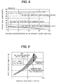
- Equation (11) When the concentration (mole %) of oxygen O 2 in the exhaust gases is known from Equation (11), gas concentration (mole %) of carbon dioxide CO 2 , nitrogen N 2 , and moisture H 2 O as the other exhaust gas components are uniquely determined.
- Fig. 5 shows the result of calculation of Equation (11).
- the gas concentrations (mole %) of the carbon dioxide CO 2 , nitrogen N 2 , and moisture H 2 O as the other exhaust gas components are uniquely determined by the relational expression, and the concentration ratio of each of the exhaust gas components is computed.
- the gas physical property values ( ⁇ , ⁇ , k, and Cp) of the total exhaust gas are obtained by the following equations.
- concentration ratio (mole %) of each of the exhaust gas components is set as Xi
- Cp ⁇ ( C p ) i ⁇ M i ⁇ X i / M / 100
- Mi molecular weight of each component
- the molecular weights Mi of the exhaust gas components for example, the molecular weights Mi of oxygen, carbon dioxide, moisture, and nitrogen are 32, 44, 18, and 28, respectively
- the concentration ratio (mole %) Xi of each of the exhaust gas components is obtained from the relational expression shown in Fig. 5.
- the density ⁇ of the total exhaust gases, the specific heat Cp at constant pressure, viscosity coefficient ⁇ , and thermal conductivity k are obtained.
- the correction amount of the output Qeo from the recirculation exhaust gas mass flowmeter 9 can be calculated on the basis of the exhaust gas component concentrations (gas physical property values ( ⁇ , ⁇ , k, Cp)) by the Equation (10).
- a method which does not use the relational expression as described above can be also employed.
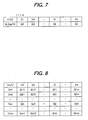
- the relation between the output V of the recirculation exhaust gas mass flowmeter 9 preliminarily subjected to the initial calibration with air and the mass flow quantity Qeo is stored as a map shown in Fig. 7. Further, as shown in Fig. 8, a corrected mass flow quantity Qij is similarly stored in the storage as a two-dimensional map of the output V of the recirculation exhaust gas mass flowmeter 9 and the oxygen concentration (Do) of the predicted recirculation exhaust gas.
- Q e 1 Q 2 + Q 22
- the more-accurate recirculation exhaust gas mass flow quantity Qe1 can be obtained with calculation time smaller than that in the case of using the relational expressions.
- the recirculation exhaust gas mass flow signal Qeo is corrected on the basis of the predicted exhaust gas component concentration Do.
- the oxygen concentration Do in the total intake air containing the recirculation exhaust gases in the cylinder and the ratio between the oxygen quantity Qo in the total intake air and the fuel injection quantity Qr(oxygen quantity/fuel injection quantity ratio, Qo/Qr) are computed with high accuracy by using the corrected recirculation exhaust gas mass flow quantity Qe1. Therefore, the exhaust recirculation control system having high response and capable of performing high-accuracy EGR control reliably achieving both of a lower quantity of smoke and reduction in NOx can be realized.
- the output V of the recirculation exhaust gas mass flowmeter 9 preliminarily subjected to the initial calibration with air is used as the recirculation exhaust gas mass flow signal QeO.
- re-calculation can be also performed by using the corrected recirculation exhaust gas mass flow Qe1 as the result of the immediately preceding calculation.
- an exhaust recirculation control system as a second embodiment of the present invention will now be described with reference to Fig. 9.
- the same reference numerals are given to components having the same configurations as those of the first embodiment of Fig. 1.
- the second embodiment is different from the first embodiment with respect to the following points: that is a configuration of the recirculation exhaust gas mass flowmeter 9 disposed in the exhaust recirculation gas passage 6; and an exhaust gas temperature sensor 25 is additionally disposed near the configuration of the recirculation exhaust gas mass flowmeter 9.
- Fig. 10 shows a circuit configuration of the recirculation exhaust gas mass flowmeter 9 and the exhaust gas temperature sensor 25 of the second embodiment.
- the heater 18 and the exhaust gas temperature sensor 25 are disposed.
- the configuration in the exhaust recirculation passage 6 is the same as that of the first embodiment but the circuit configuration is different from that of the first embodiment.
- the heater 18 and the exhaust gas temperature sensor 19 construct a bridge circuit.
- the temperature is controlled to be a predetermined heater temperature (Th) irrespective of the exhaust gas temperature (Te).
- the heater temperature (Th) By controlling the temperature to the predetermined heater temperature (Th), even in the case where the exhaust gas temperature (Te) largely changes, the heater temperature (Th) becomes constant. Consequently, the heater is not heated to an excessively high temperature, and occurrence of a trouble in the heater can be prevented.
- the exhaust gas also contains a large amount of suspended matters such as carbons. When the suspended matters such as carbon are adhered to the heater 18, the heat discharge effect (heat transmission) of the heater changes, and a sensing error occurs in the recirculation exhaust gas mass flowmeter.
- the heater temperature (Th) by controlling the heater temperature (Th) to a predetermined value of 400 °C or higher at which a baking effect is expected, adhesion of suspended matters such as carbon can be prevented, and a very reliable configuration can be realized.
- an output of the recirculation exhaust gas mass flowmeter 9 strongly depends on the exhaust gas temperature (Te) as shown in the Equations (9) and (10). Consequently, as shown in Fig. 10, the exhaust gas temperature sensor 25 is disposed in the exhaust recirculation passage 6 , an output of the exhaust gas temperature (Te) is received from a terminal 23c to the control unit 11, and an output of the heat current flowing in the heater 18 (corresponding to the voltage at the end of the resistor 22b) is corrected.
- Fig. 11 shows the exhaust recirculation control method executed by the control unit 11 of the embodiment.
- the point different from the first embodiment is that the exhaust gas temperature sensor 25 is added. Consequently, in the control unit 11, computation for predicting the exhaust gas component concentration (oxygen concentration Do) every combustion in the cylinder is performed. After that, based on the predicted exhaust gas component concentration (oxygen concentration Do) and the exhaust gas temperature (Te) of the exhaust gas temperature sensor 25, the recirculation exhaust gas mass flow quantity Qeo is corrected to obtain the corrected recirculation exhaust gas mass flow quantity Qe1.
- correction is made by using the two-dimensional map of the predicted exhaust gas component concentration (oxygen concentration Do) and the output (V) of the recirculation exhaust gas mass flowmeter 9.
- correction is made by using a three-dimensional map of the predicted exhaust gas component concentration (oxygen concentration Do), the exhaust gas temperature (Te), and the output (V) of the recirculation exhaust gas mass flowmeter 9.
- the correction amount is obtained as Qkji from the three-dimensional map of Fig. 12 on the basis of the output Vi, the oxygen concentration Dok, and the exhaust gas temperature Tej.
- the corrected recirculation exhaust gas mass flow quantity Qe1 can be calculated as follows.
- Q e 1 Q i + Q k j i
- the oxygen mass quantity Qo in the total intake air containing the recirculation exhaust gas in the cylinder and the other inert gas mass Qetc are computed.
- the oxygen concentration (Qo/ (Qo+Qetc)) in the total intake air containing the recirculation exhaust gas in the cylinder, and the ratio between the oxygen quantity in the total intake air and the fuel injection quantity (oxygen quantity/fuel injection quantity ratio) (Qo/Qr) are computed with high accuracy.
- the computed oxygen concentration (Qo/(Qo+Qetc))in total intake air and quantity/fuel injection quantity ratio (Qo/Qr) are compared with a target oxygen concentration (Qo/(Qo+Qetc)) in the total intake air and a target oxygen quantity/fuel injection quantity ratio (Qo/Qr).
- the target oxygen concentration and the target oxygen quantity/fuel injection quantity ratio are pre-set according to engine operating conditions (engine speed Ne and the accelerator position) in the storing unit. Based on the result of such a comparison, the opening of the EGR valve 7, the throttle valve 15, or a fuel injection quantity Qr of the fuel injector 14 is controlled.
- the reliability of the recirculation exhaust gas mass flowmeter 9 is improved, and the recirculation exhaust gas mass flow quantity Qe1 corrected with higher accuracy can be obtained.
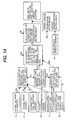
- FIG. 13 shows an exhaust recirculation controlling method executed by the control unit 11 as the third embodiment.
- learning of an error in the predicted exhaust gas component concentration is performed by using a sensing value of the oxygen concentration sensed by the oxygen concentration sensor 26, which is disposed in the exhaust circulation passage 6.
- accuracy in the steady state improves. It is determined that the operating state of the internal combustion engine is the steady state by monitoring whether or not a change with time in the engine speed Ne, the accelerator position, or the fuel injection quantity Qr is a predetermined value within certain time.
- a correction factor is stored as an error learn map every operating range determined by the engine speed Ne, the accelerator position, or the fuel injection quantity Qr. After error learning in the steady state, the correction factor is corrected and re-stored. After the error learning, the predicted exhaust gas component concentration (oxygen concentration Do2) is calculated every combustion in the cylinder.
- the exhaust oxygen concentration Do2 can be predicted with high accuracy. Therefore, by performing the EGR control or injection quantity control in accordance with the predicted exhaust oxygen concentration Do2, excellent response is obtained and control accuracy, particularly, control accuracy at the time of transition largely improves.
- the oxygen concentration sensor 26 is disposed in the exhaust recirculation passage 6 in the embodiment, similar effects of the invention can be produced even if such a disposition is adopted.
- ⁇ Th Th-Te
- Th Th-Te
- Similar effects of the invention can be produced also in the case of using a temperature difference type mass flowmeter, in which temperature sensors such as thermal sensitive resistors are respectively upstream and downstream of the heater and the mass flow is sensed from the difference of temperatures of the upstream and downstream temperature sensors.
- the oxygen concentration in the exhaust gas is estimated in the embodiments. Furthermore, in place of the oxygen concentration as seen in Equation (11) and Fig. 5, it is possible to use information of the concentration of any of carbon dioxide, moisture, and nitrogen, because the concentration ratio of the oxygen, carbon dioxide, moisture, and nitrogen as the exhaust gas components can be known. Consequently, similar effects of the aforementioned embodiments can be also produced by using prediction value of the gas concentration or sensed value of gasflow sensor other than that of the oxygen concentration or the oxygen concentration sensor.
- the high-accuracy EGR control which also deals with a rapid change in the operating conditions can be performed. And excellent effects such that the maximum reduction in NOx can be achieved while suppressing the smoke ejection quantity to be within the allowable range are obtained.
Landscapes
- Engineering & Computer Science (AREA)
- Chemical & Material Sciences (AREA)
- Combustion & Propulsion (AREA)
- Mechanical Engineering (AREA)
- General Engineering & Computer Science (AREA)
- Physics & Mathematics (AREA)
- Fluid Mechanics (AREA)
- General Physics & Mathematics (AREA)
- Analytical Chemistry (AREA)
- Exhaust-Gas Circulating Devices (AREA)
- Combined Controls Of Internal Combustion Engines (AREA)
- Output Control And Ontrol Of Special Type Engine (AREA)
Applications Claiming Priority (1)
| Application Number | Priority Date | Filing Date | Title |
|---|---|---|---|
| JP2004285649A JP4186899B2 (ja) | 2004-09-30 | 2004-09-30 | 排気還流制御装置 |
Publications (3)
| Publication Number | Publication Date |
|---|---|
| EP1643103A2 true EP1643103A2 (fr) | 2006-04-05 |
| EP1643103A3 EP1643103A3 (fr) | 2007-03-14 |
| EP1643103B1 EP1643103B1 (fr) | 2010-07-07 |
Family
ID=35483563
Family Applications (1)
| Application Number | Title | Priority Date | Filing Date |
|---|---|---|---|
| EP05018793A Expired - Lifetime EP1643103B1 (fr) | 2004-09-30 | 2005-08-30 | Méthode pour obtenir le débit de gaz d'échappement, appareil de mesure et système de commande de recyclage de gaz d'échappement |
Country Status (4)
| Country | Link |
|---|---|
| US (1) | US7155332B2 (fr) |
| EP (1) | EP1643103B1 (fr) |
| JP (1) | JP4186899B2 (fr) |
| DE (1) | DE602005022148D1 (fr) |
Cited By (7)
| Publication number | Priority date | Publication date | Assignee | Title |
|---|---|---|---|---|
| WO2008055836A1 (fr) * | 2006-11-06 | 2008-05-15 | Continental Automotive Gmbh | Module de détection pour déterminer les valeurs d'écoulement d'un flux gazeux de moteur à combustion interne |
| EP2292917A3 (fr) * | 2009-07-27 | 2011-03-30 | Hitachi Automotive Systems, Ltd. | Appareil de commande de débit de recyclage des gaz d'échappement d'un moteur à combustion interne |
| EP2290209A3 (fr) * | 2009-08-31 | 2011-10-12 | International Engine Intellectual Property Company, LLC | Commande d'oxygène à collecteur d'admission |
| CN102465779A (zh) * | 2010-11-18 | 2012-05-23 | 现代自动车株式会社 | 用于预测NOx量的方法以及使用该方法的排放系统 |
| EP2412957A3 (fr) * | 2008-05-08 | 2014-12-17 | Mitsubishi Heavy Industries, Ltd. | Unité de contrôle d'admission de carburant pour contrôler un moteur diesel |
| CN103470407B (zh) * | 2008-06-02 | 2016-08-10 | 博格华纳公司 | 通过涡轮增压的发动机系统中的多通道来控制排气再循环 |
| DE102016216236A1 (de) | 2016-08-29 | 2018-03-01 | Bayerische Motoren Werke Aktiengesellschaft | Verfahren zum Bereitstellen von Daten |
Families Citing this family (40)
| Publication number | Priority date | Publication date | Assignee | Title |
|---|---|---|---|---|
| US7555928B2 (en) * | 2002-12-05 | 2009-07-07 | Avl North America Inc. | Exhaust volume measurement device |
| JP4049158B2 (ja) * | 2005-03-09 | 2008-02-20 | トヨタ自動車株式会社 | 内燃機関の燃料噴射制御装置 |
| JP4214415B2 (ja) * | 2006-05-19 | 2009-01-28 | 三菱自動車工業株式会社 | 触媒温度推定装置 |
| JP4713437B2 (ja) * | 2006-10-18 | 2011-06-29 | 日立オートモティブシステムズ株式会社 | 内燃機関の排気ガス再循環装置 |
| JP2008180185A (ja) * | 2007-01-26 | 2008-08-07 | Hitachi Ltd | エンジンの排気還流制御装置 |
| KR100887968B1 (ko) * | 2007-11-09 | 2009-03-09 | 현대자동차주식회사 | 디젤 엔진에서 이지알 제어방법 |
| DE102008001418B4 (de) * | 2008-04-28 | 2026-02-19 | Robert Bosch Gmbh | Verfahren zum Betreiben eines Verbrennungsmotors |
| FR2943385B1 (fr) * | 2009-03-19 | 2014-07-18 | Renault Sas | Dispositif et procede de commande de l'injection de carburant dans un moteur en fonction du taux de recirculation partielle des gaz d'echappement |
| DE102009003018B4 (de) | 2009-05-12 | 2022-07-14 | Ford Global Technologies, Llc | Verfahren zum Einstellen der Abgasrückführrate in einem Abgasrückführsystem sowie Abgasrückführsystem für ein Kraftfahrzeug |
| US8042528B2 (en) * | 2009-07-31 | 2011-10-25 | Ford Global Technologies, Llc | Adaptive EGR control for internal combustion engines |
| DE102010001645B4 (de) * | 2010-02-05 | 2023-11-23 | Endress + Hauser Flowtec Ag | Verwendung eines Durchflussmessgeräts und Messsystem zur Ermittlung eines Massedurchsatzes eines Mediums |
| US8527186B2 (en) | 2010-09-08 | 2013-09-03 | Clean Air Power, Inc. | Method and apparatus for adaptive feedback control of an excess air ratio in a compression ignition natural gas engine |
| FR2965584B1 (fr) * | 2010-10-05 | 2013-06-28 | Renault Sas | Procede de determination d'un taux de gaz d'echappement recircules a l'entree d'un cylindre d'un moteur a combustion interne et moteur mettant en oeuvre un tel procede |
| US8915236B2 (en) | 2011-03-31 | 2014-12-23 | GM Global Technology Operations LLC | Systems and methods for controlling engine combustion stability |
| US9267449B2 (en) | 2011-06-16 | 2016-02-23 | GM Global Technology Operations LLC | Control system and method for coordinating throttle and boost |
| CA2844076C (fr) * | 2011-08-16 | 2017-01-17 | Transocean Sedco Forex Ventures Limited | Mesure des emissions de moteur diesel |
| US9157390B2 (en) | 2011-09-21 | 2015-10-13 | GM Global Technology Operations LLC | Selective exhaust gas recirculation diagnostic systems and methods |
| EP2623753A3 (fr) * | 2012-01-31 | 2015-09-16 | International Engine Intellectual Property Company, LLC | Commande de NOx |
| US9222426B2 (en) * | 2012-02-17 | 2015-12-29 | Ford Global Technologies, Llc | Transient air flow control |
| US9249764B2 (en) | 2012-03-06 | 2016-02-02 | GM Global Technology Operations LLC | Engine control systems and methods with humidity sensors |
| US10066564B2 (en) | 2012-06-07 | 2018-09-04 | GM Global Technology Operations LLC | Humidity determination and compensation systems and methods using an intake oxygen sensor |
| US9932917B2 (en) | 2012-03-21 | 2018-04-03 | GM Global Technology Operations LLC | Exhaust gas recirculation control systems and methods |
| US20130268176A1 (en) * | 2012-04-05 | 2013-10-10 | GM Global Technology Operations LLC | Exhaust gas recirculation control systems and methods for low engine delta pressure conditions |
| US20130298882A1 (en) * | 2012-05-14 | 2013-11-14 | Caterpillar, Inc. | EGR with Temperature Controlled Venturi Flow Meter |
| CN102840995B (zh) * | 2012-09-10 | 2015-03-25 | 临海市伟达汽车部件有限公司 | Egr冷却器性能测试分析系统 |
| US9014947B2 (en) | 2012-10-25 | 2015-04-21 | Ford Global Technologies, Llc | Exhaust-gas regeneration under rich conditions to improve fuel economy |
| KR102030181B1 (ko) * | 2012-12-24 | 2019-10-08 | 두산인프라코어 주식회사 | 배기가스 재순환장치 및 이의 제어 방법 |
| US9341133B2 (en) | 2013-03-06 | 2016-05-17 | GM Global Technology Operations LLC | Exhaust gas recirculation control systems and methods |
| US9631567B2 (en) | 2013-08-15 | 2017-04-25 | GM Global Technology Operations LLC | Sensor based measurement and purge control of fuel vapors in internal combustion engines |
| JP6259246B2 (ja) * | 2013-10-09 | 2018-01-10 | 三菱重工業株式会社 | 内燃機関の制御装置 |
| JP6079740B2 (ja) * | 2014-09-30 | 2017-02-15 | マツダ株式会社 | エンジンの燃料制御装置 |
| US10732135B2 (en) * | 2015-06-16 | 2020-08-04 | Multicore Technologies, Llc | System and method for determining one or more fluid concentrations in a fluid stream |
| DE102015216303B3 (de) * | 2015-08-26 | 2016-09-29 | Ford Global Technologies, Llc | Korrektur einer eingespritzten Brennstoffmenge |
| CN108884739B (zh) * | 2016-03-02 | 2021-03-09 | 沃特洛电气制造公司 | 用于流体流动系统的感受器 |
| CN106351754B (zh) * | 2016-08-29 | 2019-08-13 | 上海交通大学 | 发动机废气再循环率的测量方法 |
| JP6707038B2 (ja) * | 2017-01-23 | 2020-06-10 | 日立オートモティブシステムズ株式会社 | 内燃機関の制御装置 |
| DE112018000548B4 (de) * | 2017-03-30 | 2024-05-29 | Cummins Inc. | Motorsteuerungen mit direkter Regelung des Zylinderinnen-Sauerstoffs |
| CN110686890B (zh) * | 2019-10-23 | 2021-08-27 | 中船动力有限公司 | 在线柴油机气阀状态检测方法 |
| WO2024135153A1 (fr) * | 2022-12-21 | 2024-06-27 | 株式会社堀場製作所 | Système de mesure de gaz, procédé de mesure de gaz et programme de mesure de gaz |
| CN115839282B (zh) * | 2023-02-17 | 2023-05-09 | 西安陕柴重工核应急装备有限公司 | 基于发电机组的燃油系统构建方法及装置 |
Citations (2)
| Publication number | Priority date | Publication date | Assignee | Title |
|---|---|---|---|---|
| JPH09126060A (ja) | 1995-11-08 | 1997-05-13 | Isuzu Motors Ltd | 排気還流制御方法及びその装置 |
| JP2003516496A (ja) | 1999-12-10 | 2003-05-13 | ヘレーウス エレクトロ−ナイト インターナシヨナル エヌ ヴイ | 車両の内燃機関の吸気領域への排気ガス再循環方法および装置 |
Family Cites Families (6)
| Publication number | Priority date | Publication date | Assignee | Title |
|---|---|---|---|---|
| JPS56104253A (en) * | 1980-01-24 | 1981-08-19 | Matsushita Electric Ind Co Ltd | Flow rate sensor |
| US6347519B1 (en) * | 2000-03-31 | 2002-02-19 | Detroit Diesel Corporation | System and method for measuring recirculated exhaust gas flow in a compression-ignition engine |
| JP4284906B2 (ja) | 2001-02-28 | 2009-06-24 | 株式会社デンソー | 内燃機関の制御装置 |
| JP3751930B2 (ja) * | 2002-11-01 | 2006-03-08 | トヨタ自動車株式会社 | 内燃機関のegrガス温度推定装置 |
| JP4192763B2 (ja) * | 2003-11-07 | 2008-12-10 | 株式会社日立製作所 | 電子式egrガス制御装置 |
| JP2005248748A (ja) * | 2004-03-02 | 2005-09-15 | Isuzu Motors Ltd | ディーゼルエンジン |
-
2004
- 2004-09-30 JP JP2004285649A patent/JP4186899B2/ja not_active Expired - Fee Related
-
2005
- 2005-08-29 US US11/212,769 patent/US7155332B2/en not_active Expired - Lifetime
- 2005-08-30 DE DE602005022148T patent/DE602005022148D1/de not_active Expired - Lifetime
- 2005-08-30 EP EP05018793A patent/EP1643103B1/fr not_active Expired - Lifetime
Patent Citations (2)
| Publication number | Priority date | Publication date | Assignee | Title |
|---|---|---|---|---|
| JPH09126060A (ja) | 1995-11-08 | 1997-05-13 | Isuzu Motors Ltd | 排気還流制御方法及びその装置 |
| JP2003516496A (ja) | 1999-12-10 | 2003-05-13 | ヘレーウス エレクトロ−ナイト インターナシヨナル エヌ ヴイ | 車両の内燃機関の吸気領域への排気ガス再循環方法および装置 |
Cited By (11)
| Publication number | Priority date | Publication date | Assignee | Title |
|---|---|---|---|---|
| WO2008055836A1 (fr) * | 2006-11-06 | 2008-05-15 | Continental Automotive Gmbh | Module de détection pour déterminer les valeurs d'écoulement d'un flux gazeux de moteur à combustion interne |
| EP2412957A3 (fr) * | 2008-05-08 | 2014-12-17 | Mitsubishi Heavy Industries, Ltd. | Unité de contrôle d'admission de carburant pour contrôler un moteur diesel |
| US9008951B2 (en) | 2008-05-08 | 2015-04-14 | Mitsubishi Heavy Industries, Ltd. | Fuel admission control unit to control a diesel engine |
| CN103470407B (zh) * | 2008-06-02 | 2016-08-10 | 博格华纳公司 | 通过涡轮增压的发动机系统中的多通道来控制排气再循环 |
| EP2292917A3 (fr) * | 2009-07-27 | 2011-03-30 | Hitachi Automotive Systems, Ltd. | Appareil de commande de débit de recyclage des gaz d'échappement d'un moteur à combustion interne |
| US8387593B2 (en) | 2009-07-27 | 2013-03-05 | Hitachi Automotive Systems, Ltd. | EGR flow rate control apparatus of internal combustion engine |
| EP2290209A3 (fr) * | 2009-08-31 | 2011-10-12 | International Engine Intellectual Property Company, LLC | Commande d'oxygène à collecteur d'admission |
| CN102465779A (zh) * | 2010-11-18 | 2012-05-23 | 现代自动车株式会社 | 用于预测NOx量的方法以及使用该方法的排放系统 |
| EP2455599A3 (fr) * | 2010-11-18 | 2014-09-03 | Hyundai Motor Company | Procédé pour prédire une quantité de NOx et système d'échappement utilisant ce procédé |
| CN102465779B (zh) * | 2010-11-18 | 2016-08-17 | 现代自动车株式会社 | 用于预测NOx量的方法以及使用该方法的排放系统 |
| DE102016216236A1 (de) | 2016-08-29 | 2018-03-01 | Bayerische Motoren Werke Aktiengesellschaft | Verfahren zum Bereitstellen von Daten |
Also Published As
| Publication number | Publication date |
|---|---|
| JP4186899B2 (ja) | 2008-11-26 |
| DE602005022148D1 (de) | 2010-08-19 |
| US7155332B2 (en) | 2006-12-26 |
| US20060069494A1 (en) | 2006-03-30 |
| EP1643103B1 (fr) | 2010-07-07 |
| EP1643103A3 (fr) | 2007-03-14 |
| JP2006097597A (ja) | 2006-04-13 |
Similar Documents
| Publication | Publication Date | Title |
|---|---|---|
| EP1643103B1 (fr) | Méthode pour obtenir le débit de gaz d'échappement, appareil de mesure et système de commande de recyclage de gaz d'échappement | |
| US6877369B2 (en) | EGR-gas flow rate estimation apparatus for internal combustion engine | |
| US6457353B1 (en) | Apparatus of diagnosing an internal combustion engine and a method of diagnosing of an internal combustion engine | |
| ES2758794T3 (es) | Método y aparato para medir y controlar la tasa de EGR en un motor de combustión | |
| EP2284376B1 (fr) | Dispositif de recirulation de gaz d'échappement pour moteur à combushion interne | |
| US10323583B2 (en) | Method for determining the oxygen concentration O2 in a gas flow | |
| EP2292917B1 (fr) | Appareil de commande de débit de recyclage des gaz d'échappement d'un moteur à combustion interne | |
| JPH10141147A (ja) | Egr装置付き内燃機関 | |
| JP2003516496A (ja) | 車両の内燃機関の吸気領域への排気ガス再循環方法および装置 | |
| JP2010203281A (ja) | Egr制御装置 | |
| US6453229B1 (en) | Air-fuel ratio control device for internal combustion engine and method thereof | |
| US10995644B2 (en) | Method for distinguishing between model inaccuracies and lambda offsets for a model-based control of the fill level of a catalytic converter | |
| US10138831B2 (en) | Controller and control method for internal combustion engine | |
| US6378508B1 (en) | Process and system for automatically controlling the fraction of the exhaust gas quantity returned to an internal-combustion engine | |
| US7063081B2 (en) | Deterioration determining apparatus and deterioration determining method for oxygen sensor | |
| US11371453B2 (en) | Method for regulating a fill of an exhaust component storage of a catalyst | |
| EP3128159B1 (fr) | Procédé de régulation d'un circuit egr de recirculation des gaz d'échappement rge basse pression dans un moteur à combustion interne | |
| JP2001182574A (ja) | Egrシステムとその制御方法 | |
| JPS62261645A (ja) | エンジン制御装置 | |
| JP2004170357A (ja) | 排ガス流量計測装置及び排ガスの流量計測方法 | |
| EP3128158B1 (fr) | Procédé de contrôle d'un circuit egr de recyclage de gas d'échappement basse pression dans un moteur à combustion interne | |
| JP2006316706A (ja) | 内燃機関の排気ガス還流装置及び制御方法 | |
| JPH04112939A (ja) | 内燃機関の空燃比制御装置 |
Legal Events
| Date | Code | Title | Description |
|---|---|---|---|
| PUAI | Public reference made under article 153(3) epc to a published international application that has entered the european phase |
Free format text: ORIGINAL CODE: 0009012 |
|
| AK | Designated contracting states |
Kind code of ref document: A2 Designated state(s): AT BE BG CH CY CZ DE DK EE ES FI FR GB GR HU IE IS IT LI LT LU LV MC NL PL PT RO SE SI SK TR |
|
| AX | Request for extension of the european patent |
Extension state: AL BA HR MK YU |
|
| PUAL | Search report despatched |
Free format text: ORIGINAL CODE: 0009013 |
|
| AK | Designated contracting states |
Kind code of ref document: A3 Designated state(s): AT BE BG CH CY CZ DE DK EE ES FI FR GB GR HU IE IS IT LI LT LU LV MC NL PL PT RO SE SI SK TR |
|
| AX | Request for extension of the european patent |
Extension state: AL BA HR MK YU |
|
| 17P | Request for examination filed |
Effective date: 20070914 |
|
| 17Q | First examination report despatched |
Effective date: 20071023 |
|
| AKX | Designation fees paid |
Designated state(s): DE FR |
|
| GRAP | Despatch of communication of intention to grant a patent |
Free format text: ORIGINAL CODE: EPIDOSNIGR1 |
|
| GRAS | Grant fee paid |
Free format text: ORIGINAL CODE: EPIDOSNIGR3 |
|
| GRAA | (expected) grant |
Free format text: ORIGINAL CODE: 0009210 |
|
| AK | Designated contracting states |
Kind code of ref document: B1 Designated state(s): DE FR |
|
| REF | Corresponds to: |
Ref document number: 602005022148 Country of ref document: DE Date of ref document: 20100819 Kind code of ref document: P |
|
| PLBE | No opposition filed within time limit |
Free format text: ORIGINAL CODE: 0009261 |
|
| STAA | Information on the status of an ep patent application or granted ep patent |
Free format text: STATUS: NO OPPOSITION FILED WITHIN TIME LIMIT |
|
| REG | Reference to a national code |
Ref country code: FR Ref legal event code: ST Effective date: 20110502 |
|
| 26N | No opposition filed |
Effective date: 20110408 |
|
| REG | Reference to a national code |
Ref country code: DE Ref legal event code: R097 Ref document number: 602005022148 Country of ref document: DE Effective date: 20110408 |
|
| PG25 | Lapsed in a contracting state [announced via postgrant information from national office to epo] |
Ref country code: FR Free format text: LAPSE BECAUSE OF NON-PAYMENT OF DUE FEES Effective date: 20100907 |
|
| PGFP | Annual fee paid to national office [announced via postgrant information from national office to epo] |
Ref country code: DE Payment date: 20140827 Year of fee payment: 10 |
|
| REG | Reference to a national code |
Ref country code: DE Ref legal event code: R119 Ref document number: 602005022148 Country of ref document: DE |
|
| PG25 | Lapsed in a contracting state [announced via postgrant information from national office to epo] |
Ref country code: DE Free format text: LAPSE BECAUSE OF NON-PAYMENT OF DUE FEES Effective date: 20160301 |