EP1643230A1 - Verfahren und Vorrichtung zur Kontrolle der Dichtheit eines Mantels enthaltend Druckgas - Google Patents
Verfahren und Vorrichtung zur Kontrolle der Dichtheit eines Mantels enthaltend Druckgas Download PDFInfo
- Publication number
- EP1643230A1 EP1643230A1 EP05292038A EP05292038A EP1643230A1 EP 1643230 A1 EP1643230 A1 EP 1643230A1 EP 05292038 A EP05292038 A EP 05292038A EP 05292038 A EP05292038 A EP 05292038A EP 1643230 A1 EP1643230 A1 EP 1643230A1
- Authority
- EP
- European Patent Office
- Prior art keywords
- values
- parameter
- parameters
- rephased
- time
- Prior art date
- Legal status (The legal status is an assumption and is not a legal conclusion. Google has not performed a legal analysis and makes no representation as to the accuracy of the status listed.)
- Granted
Links
- 238000000034 method Methods 0.000 title claims abstract description 54
- 230000008569 process Effects 0.000 title claims description 8
- 238000005259 measurement Methods 0.000 claims abstract description 20
- 238000012360 testing method Methods 0.000 claims description 50
- 230000010363 phase shift Effects 0.000 claims description 34
- 230000006870 function Effects 0.000 claims description 30
- 239000004698 Polyethylene Substances 0.000 claims description 7
- -1 polyethylene Polymers 0.000 claims description 7
- 229920000573 polyethylene Polymers 0.000 claims description 7
- 238000011065 in-situ storage Methods 0.000 claims description 6
- 238000012545 processing Methods 0.000 claims description 5
- FGUUSXIOTUKUDN-IBGZPJMESA-N C1(=CC=CC=C1)N1C2=C(NC([C@H](C1)NC=1OC(=NN=1)C1=CC=CC=C1)=O)C=CC=C2 Chemical compound C1(=CC=CC=C1)N1C2=C(NC([C@H](C1)NC=1OC(=NN=1)C1=CC=CC=C1)=O)C=CC=C2 FGUUSXIOTUKUDN-IBGZPJMESA-N 0.000 claims description 3
- 239000007789 gas Substances 0.000 description 38
- 238000010586 diagram Methods 0.000 description 10
- 238000009826 distribution Methods 0.000 description 9
- 238000004364 calculation method Methods 0.000 description 8
- 102100022934 DPH3 homolog Human genes 0.000 description 5
- 101000902716 Homo sapiens DPH3 homolog Proteins 0.000 description 5
- PXFBZOLANLWPMH-UHFFFAOYSA-N 16-Epiaffinine Natural products C1C(C2=CC=CC=C2N2)=C2C(=O)CC2C(=CC)CN(C)C1C2CO PXFBZOLANLWPMH-UHFFFAOYSA-N 0.000 description 4
- 230000008859 change Effects 0.000 description 4
- 238000005070 sampling Methods 0.000 description 4
- 230000004048 modification Effects 0.000 description 3
- 238000012986 modification Methods 0.000 description 3
- 102100024830 2-(3-amino-3-carboxypropyl)histidine synthase subunit 2 Human genes 0.000 description 2
- 101000909233 Homo sapiens 2-(3-amino-3-carboxypropyl)histidine synthase subunit 2 Proteins 0.000 description 2
- 230000010365 information processing Effects 0.000 description 2
- 238000012417 linear regression Methods 0.000 description 2
- 239000000463 material Substances 0.000 description 2
- 238000011002 quantification Methods 0.000 description 2
- 238000007789 sealing Methods 0.000 description 2
- 238000003860 storage Methods 0.000 description 2
- 102100031599 2-(3-amino-3-carboxypropyl)histidine synthase subunit 1 Human genes 0.000 description 1
- 101000866191 Homo sapiens 2-(3-amino-3-carboxypropyl)histidine synthase subunit 1 Proteins 0.000 description 1
- 101100063974 Neurospora crassa (strain ATCC 24698 / 74-OR23-1A / CBS 708.71 / DSM 1257 / FGSC 987) dph-3 gene Proteins 0.000 description 1
- 238000009529 body temperature measurement Methods 0.000 description 1
- 230000007547 defect Effects 0.000 description 1
- 230000002950 deficient Effects 0.000 description 1
- 238000001514 detection method Methods 0.000 description 1
- 101150063755 dph-1 gene Proteins 0.000 description 1
- 238000004519 manufacturing process Methods 0.000 description 1
- 230000008439 repair process Effects 0.000 description 1
- 230000004044 response Effects 0.000 description 1
- 230000000717 retained effect Effects 0.000 description 1
Images

Classifications
-
- G—PHYSICS
- G01—MEASURING; TESTING
- G01M—TESTING STATIC OR DYNAMIC BALANCE OF MACHINES OR STRUCTURES; TESTING OF STRUCTURES OR APPARATUS, NOT OTHERWISE PROVIDED FOR
- G01M3/00—Investigating fluid-tightness of structures
- G01M3/02—Investigating fluid-tightness of structures by using fluid or vacuum
- G01M3/26—Investigating fluid-tightness of structures by using fluid or vacuum by measuring rate of loss or gain of fluid, e.g. by pressure-responsive devices, by flow detectors
- G01M3/28—Investigating fluid-tightness of structures by using fluid or vacuum by measuring rate of loss or gain of fluid, e.g. by pressure-responsive devices, by flow detectors for pipes, cables or tubes; for pipe joints or seals; for valves ; for welds
- G01M3/2892—Investigating fluid-tightness of structures by using fluid or vacuum by measuring rate of loss or gain of fluid, e.g. by pressure-responsive devices, by flow detectors for pipes, cables or tubes; for pipe joints or seals; for valves ; for welds for underground fuel dispensing systems
-
- G—PHYSICS
- G01—MEASURING; TESTING
- G01M—TESTING STATIC OR DYNAMIC BALANCE OF MACHINES OR STRUCTURES; TESTING OF STRUCTURES OR APPARATUS, NOT OTHERWISE PROVIDED FOR
- G01M3/00—Investigating fluid-tightness of structures
- G01M3/02—Investigating fluid-tightness of structures by using fluid or vacuum
- G01M3/26—Investigating fluid-tightness of structures by using fluid or vacuum by measuring rate of loss or gain of fluid, e.g. by pressure-responsive devices, by flow detectors
- G01M3/32—Investigating fluid-tightness of structures by using fluid or vacuum by measuring rate of loss or gain of fluid, e.g. by pressure-responsive devices, by flow detectors for containers, e.g. radiators
Definitions
- the present invention relates to a method and a device for checking the tightness of an enclosure containing a gas under pressure and comprising a wall at least a part of which is in contact with an external environment whose temperature is variable.
- a difficulty lies in the fact that if the controls are made from observations of the gas pressure inside the tank or pipe, it is not easy to know what is the share of the evolution. the pressure related to changes in temperature and what is the part of the evolution of the pressure whose origin is due to a lack of tightness of the wall of the tank or pipe.
- the present invention aims to overcome the above disadvantages and to allow a reliable in situ control of the tightness of a tank or pipe already in place, with a quantification of the possible leak caused by a leakage .
- the invention makes it possible to overcome the evolutions of pressure due to the outside temperature and also applies to tanks or pipes most of which are buried, since at least part of this reservoir or this pipe is in contact with an external environment.
- the invention also aims to enable leak detection in situ on tanks or pipes partially buried without the need to perform measurements on buried parts difficult to access.
- the correlation method used is the least squares method.
- obtaining the ⁇ phase shift for which the correlation is optimal may be faster if the search is performed by dichotomy.
- step f) of reinflation of the values of the first parameter P (t) rephased the search for the best correlation between the set of values of the first parameter P (t) rephased and resumed by a quantity ⁇ P (t) and the set of values of the second parameter Ta (t) rephased is performed by the least squares method.
- the re-inflation ⁇ P (t) can be obtained more rapidly by proceeding by dichotomy.
- said sets of values of the first parameter P (t) and the second parameter Ta (t) acquired during the measurements each comprise between a few thousand and a few tens of thousands of acquired values.
- the time interval [t 1 t 2 ] defined by said predetermined instants t 1 t 2 may have any finite duration as long as the sampling is sufficiently accurate.
- the method is ideally suited for tightness checks of a pipe of a duration between 4h and 48h and preferably between 6h and 12h.
- the method according to the invention can be applied to any type of closed tank and more particularly to a buried pipe for conveying or distributing gas under pressure, this pipe being able to be of any type of material, including in particular polyethylene.
- the means for measuring sets of values of the first and second parameters P (t), Ta (t) each comprise acquisition means of a few thousand to a few tens of thousands of values at times different from a range. predetermined time (t 1 , t 2 ).
- the device may include power supply means for use in situ autonomously.
- the pressurized gas may be a test gas such as compressed air.
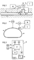
- Figure 1 illustrates the application of the invention to the tightness control of a buried pipe 50 having a wall for example polyethylene.
- the pipe 50 is essentially buried throughout its length, but comprises at least a portion in contact with the external environment.
- This part may comprise in particular a branch 51, provided with a shut-off valve not shown and which allows in particular the connection by a line 12 to an external source 11 of pressurized gas which can serve as test gas such as 'pressurized air.
- the stopcock is always in contact with the outside, even if part of the connection 51 can be buried.
- the invention can also be implemented directly with a pipe inside which is a pressurized service gas.
- the part in contact with the external environment may also be a part of the pipe 50 on which were made welds 52, 53 and which are more fragile parts may require more frequent repairs.
- FIG. 1 There is shown in Figure 1 a defect 54 of the pipe 50, which can cause a leakage of gas outside the pipe. It is this kind of leak that the method and the device according to the invention can detect while evaluating the magnitude.
- Figure 1 shows a device 41 for measuring the ambient temperature Ta (t) in the vicinity of the parts of the pipe 50 which are not buried.
- a device 31 for measuring the pressure P (t) inside the pipe 50 is also used and can measure the pressure, for example at the branch 51.
- the measuring devices 31, 41 are adapted to measure the pressure and temperature as a function of time by performing a series of successive measurements in a predetermined time interval t 1 t 2 .
- the measuring devices 31, 41 are connected to a device 20 for exploiting the measurements which will be described in more detail with reference to FIG.
- buried portions are subjected to an earth temperature Tt which can be regarded as constant at least during a leak test and other non-buried portions are subjected to an external ambient temperature Ta ( t) which varies with time.
- the pipe portions in contact with the external ambient temperature contribute to making the internal mean temperature of the pipe Ti (t) sensitive to variations in the external ambient temperature.
- T i ( t ) ( T at ( t ) ⁇ V at + T t ⁇ V t ) / ( V at + V t ) , hence the coefficients of the affine function (2)
- This phase shift ⁇ may be due to the response time of the pipe to the temperature change and / or the location of the temperature sensor relative to the uncovered portions of the network.
- the method according to the invention makes it possible to determine the evolution of the pressure inside the pipe 50 as a function of the external ambient temperature, which is an easily measurable parameter.
- the method according to the invention adopts a step that eliminates the need to find the average internal temperature Ti (t) which is very difficult or impossible to measure.
- FIG. 2 shows the application of the invention to the search for a leak in a closed tank 60 provided with a gas filling connector 61, which tank 60 is in full or partial contact with an external atmosphere at a variable temperature Ta (t).
- a leak 64 in the wall of the tank 60 as well as measuring means 31 of the internal pressure P (t) of gas in the tank 60, and measuring means 41 of the external ambient temperature Ta (t) which are analogous to the measuring means illustrated in Figure 1.
- a tank 11 of test gas such as compressed air
- a line 12 at the connector 61 for applying to the closed reservoir 60 a pressurized test gas during the time of conducting a leak test.
- a leak test may, however, be carried out according to the same principles if, instead of a test gas, a storage gas intended for operation has been introduced into the tank.
- the measuring means 31 and 41 are connected to a processing device 20 which will be described in more detail with reference to FIG.
- FIG. 3 illustrates in block diagram form the main components of the information processing device P (t) and Ta (t) delivered by the measuring devices 31 and 41.
- the device 20 may be equipped with a power supply source 27, such as a battery or batteries, so that it can be used in situ autonomously.
- a power supply source 27 such as a battery or batteries, so that it can be used in situ autonomously.
- the information processing device 20 essentially comprises a central processing unit 21, memory units 22, 23, a clock 24, software 25 and a display screen 26.
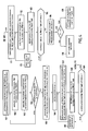
- a gas under pressure for example a test gas from a source 11 of test gas, such as compressed air a time interval ⁇ t between instants t 1 and t 2 is determined for carrying out the control test.
- This time interval ⁇ t may have any finite duration as long as a sufficiently high sampling frequency has been chosen.
- the time interval ⁇ t can be for example of the order of 4h to 48h and preferably of the order of 6h to 12h.
- the sampling frequency for the measurements that will be acquired from the pressure measuring means 31 and the temperature measuring means 41 is also determined during this first step 101. This frequency is preferably such that one performs several measurements per minute.
- steps 102 and 103 the values of the pressure P (t) inside the chamber 50, 60 as a function of time are measured respectively and the values of the ambient temperature Ta (t) are measured. ) as a function of time.
- a test 104 makes it possible to determine whether the time interval of the test [t 1 , t 2 ] has elapsed or not.
- the test 104 makes it possible to proceed to steps of processing the values measured previously.
- step 105 the pressure P (t) is expressed as a function of the external ambient temperature Ta (t) for all the measured values of these parameters P (t) and Ta (t) in the interval of time [t 1 , t 2 ].
- step 106 the phase shift ⁇ and the leakage value per unit of time ⁇ are initialized.
- step 107 a time shift ⁇ is shifted from the sets of values of the parameters P (t) and Ta (t) in the time interval [t 1 , t 2 ].
- step 108 a regression is performed and a correlation computation of the sets of rephased values with the phase shift ⁇ of the parameters P (t) and Ta (t) is carried out.
- step 109 a test is made to determine whether the correlation between the pressure P (t) and the ambient temperature Ta (t) is optimal.
- step 107 is returned via a step 110 during which the phase shift ⁇ is modified.
- This modification can be incremental, but can also be done by any other method allowing a Quickly obtain the phase shift.
- the modification of the phase shift can also be effected advantageously by dichotomy.
- step 111 If the test 109 reveals that the correlation which has just been calculated is optimal, proceed to step 111 during which the files of the rephased values of the parameters P (t) and Ta (t) are recorded with the phase shift ⁇ corresponding to the optimal correlation.
- step 113 a regression is performed and a correlation computation is performed between the set of values of the parameter P (t) rephased and virtually re-inflated by a quantity ⁇ P (t) and the set of values of the parameter. Ta (t) rephased.
- step 114 a test is carried out in step 114 to examine whether the correlation between the parameters P (t) and Ta (t) just calculated is optimal.
- step 115 a change in the value of the leak per unit of time ⁇ and return to step 112.
- This modification can be incremental, but it can also be carried out by any other method allowing a fast obtaining of the value of leakage per unit of time.
- the change of the leakage value per unit time ⁇ can also advantageously be done by dichotomy.
- step 114 If instead the test of step 114 reveals that the correlation just calculated is optimal, go to step 116 during which the value ⁇ corresponding to the optimal correlation is recorded.
- a test at step 117 makes it possible to check whether the value ⁇ finally retained and recorded is zero or not.
- step 118 If the value of ⁇ is zero, or if in practice the value of ⁇ is in the tolerance interval close to zero due to the measurement of the sensors or any other component of the device (ie if
- the value of ⁇ is not zero and lies outside the tolerance interval (- ⁇ , + ⁇ ) attributable to the uncertainty of the measurements of the sensors or of any other component of the measuring device, displays in step 119 the value ⁇ finally selected and recorded, which value ⁇ indicates that the enclosure to be tested is defective and has a leakage.
- the final ⁇ value makes it possible to quantify the leak per unit of time.
- step 106 'of initialization of the phase shift ⁇ and of the value ⁇ corresponding to the leak per unit of time can be located immediately after step 101 of FIG. determining the time interval [t 1 t 2 ] and determining the sampling frequency.
- the test 104 'for determining whether the time interval [t 1 t 2 ] has elapsed is located after the leakage display step 118, instead of being located between step 103 of measuring the value of the ambient temperature Ta (t) as a function of time and the step 105 of expressing P (t) as a function of Ta (t) for the set of values measured in the time interval [t 1 t 2] .
- step 104 After the test of the step 104 ', if the time interval [t 1 t 2 ] has not elapsed, there is a return to the step 102 of measuring the pressure value P (t) according to time. If, on the other hand, the time interval [t 1 t 2] is passed, there is a step 120 of end of test and display that the enclosure is sealed.
- the flowchart in Figure 9 lends itself to fast correlation calculation methods, such as dichotomy, and allows for quick identification of whether or not a leak exists.
- the user can then adjust the time required to obtain a stable display of the value ⁇ giving the leak per unit of time (step 119).
- the time interval [t 1 t 2 ] may be of reduced duration, for example from 5 to 10 minutes, if it is simply a matter of first establishing whether there is a leak or not. In this case, if at the end of this brief lapse of time there is no no leakage display at step 120, the process can be continued for several hours to accurately characterize at step 119 the importance of flight.
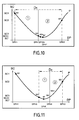
- This method converges rapidly to the DPH solution which corresponds to the minimum of the SC * function.
- the number of iterations may be for example about 20 in the context of the present application.
- Step 1
- M1 is the point corresponding to the initial phase shift DPH1 (presumed solution, often zero).
- M2 is the point corresponding to the maxIMAL DPH2 phase shift allowed for scanning.
- DPH 3 ( DPH 1 + DPH two ) / two .
- Step 1 The principle of Step 1 is reiterated by limiting the study domain to D2 defined by the interval [DPH3, DPH2].
- Step 1 The principle of Step 1 is reiterated by limiting the study domain to Dn defined by the interval [DPHn + 1, DPHn].
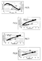
- FIGS. 5 to 8 illustrate different phases of the method according to the invention from a particular example corresponding to a leak test of a polyethylene gas distribution pipe, this test having given rise to the acquisition of 15 000 measured values of the internal pressure P (t) of the compressed air-filled pipe and 15 000 measurements of the external ambient temperature Ta (t) in the vicinity of the unburied parts of the pipeline, the values measured being distributed over a time interval ⁇ t equal to 24 h.
- FIG. 5 shows the curve 201 corresponding to the different values of the pressure P (t) measured at successive moments of measurement of the duration of the test ⁇ t, as well as the curve 202 corresponding to the different values of the ambient temperature Ta (t) measured at successive instants of measurement of the duration of the test ⁇ t.
- the two curves 201 and 202 have a phase shift ⁇ which corresponds in this example to 780 measurement points.
- FIG. 6 illustrates the result of the steps of the method according to the invention consisting in expressing the measured pressure values P (t) as a function of the outside ambient temperature Ta (t), in making a regression and in calculating the correlation between the two. parameters P (t) and Ta (t).
- FIG. 7 illustrates the result of the steps of the method according to the invention consisting in performing a relative shift between the files of the measured pressure values P (t) and the files of the measured ambient temperature values Ta (t) until obtaining the offset giving the best correlation between the two parameters P (t) and Ta (t).
- FIG. 7 thus shows the diagram 204 giving the pressure values P (t) measured and "rephased” as a function of the measured ambient temperature values Ta (t). If there were no leaks, the diagram in Figure 7 should correspond to a perfect line, since the phase shift ⁇ in Figure 5 was compensated by the relative offset between the measured value files of the pressure P (t) and the ambient temperature Ta (t). This is not the case, which means that a leak ⁇ exists.
- the chamber to be controlled is thus virtually re-inflated until the best correlation is obtained between the pressure values P (t) and ambient temperature Ta (t).
- FIG. 8 illustrates the diagram giving the measured, rephased and "boosted" pressure values P (t) as a function of the measured ambient temperature values Ta (t).
- the diagram 205 of FIG. 8 represents a line that expresses the best correlation between the parameters P (t) and Ta (t).
- the leakage ⁇ value per unit of time corresponding to the best correlation between the parameters P (t) and Ta (t) quantifies the importance of the leak detected.
- the correlation calculations between the parameters P (t) and Ta (t) can be carried out in various ways.
- the correlation calculations can be performed using the least squares method, but one could also simply use the calculation of the correlation coefficient R 2 for example.
- the deviation gap is squared.
- phase shift ⁇ is found when the sum of the set of squared deviations is minimal.
- the coefficients a and b of the linear regression are calculated for each inflation value ⁇ .
- the inflation ⁇ P (t) corresponding to the actual leak ⁇ is found when the sum of the set of deviations squared is minimal.
- the method according to the invention can be implemented with relatively inexpensive components, since it is not necessary to carry out extremely complex calculations.
- the control device can therefore be realized economically.
- the method according to the invention because of its accuracy, can authorize conducting in a single measurement campaign a strength test and a control test. which reduces the total cost for operators of gas distribution networks.
- the polyethylene gas distribution pipes generally undergo two pressure tests.
- a first test is performed with a pressure corresponding to 1.5 times the operating pressure for a very short time.
- a second so-called sealing test is performed at the same pressure or, most of the time, at a lower pressure, but over a much longer period.
- the traditional leakproofness test is preferably carried out separately at a lower pressure than that of the mechanical strength test, in particular because the influence of the temperature increases with the increase of the pressure: at a pressure of 1 bar and a temperature of 17 ° C, a variation of one degree causes a change in pressure of 6.99 mbar while it is 24.35 mbar at 6 bar, nearly 3 times the variation at 1 bar .
- the method according to the invention makes it possible to fully control the influence of the temperature, it is possible to couple the two tests and to perform a leaktightness test at a pressure compatible with the strength test, This reduces the overall time taken for the tests while maintaining a precision compatible with the safety requirements.
Landscapes
- Physics & Mathematics (AREA)
- General Physics & Mathematics (AREA)
- Examining Or Testing Airtightness (AREA)
- Sealing Devices (AREA)
Applications Claiming Priority (1)
| Application Number | Priority Date | Filing Date | Title |
|---|---|---|---|
| FR0410414A FR2876183B1 (fr) | 2004-10-01 | 2004-10-01 | Procede et dispositif de controle d'etancheite d'une enceinte contenant un gaz sous pression |
Publications (2)
| Publication Number | Publication Date |
|---|---|
| EP1643230A1 true EP1643230A1 (de) | 2006-04-05 |
| EP1643230B1 EP1643230B1 (de) | 2010-04-28 |
Family
ID=34949240
Family Applications (1)
| Application Number | Title | Priority Date | Filing Date |
|---|---|---|---|
| EP05292038A Expired - Lifetime EP1643230B1 (de) | 2004-10-01 | 2005-09-30 | Verfahren und Vorrichtung zur Kontrolle der Dichtheit einer Umhüllung enthaltend ein Druckgas |
Country Status (5)
| Country | Link |
|---|---|
| EP (1) | EP1643230B1 (de) |
| AT (1) | ATE466266T1 (de) |
| DE (1) | DE602005020888D1 (de) |
| ES (1) | ES2344791T3 (de) |
| FR (1) | FR2876183B1 (de) |
Cited By (8)
| Publication number | Priority date | Publication date | Assignee | Title |
|---|---|---|---|---|
| FR3031178A1 (fr) * | 2014-12-30 | 2016-07-01 | Isp Aquitaine | Dispositif de verification de l'etancheite |
| CN108918045A (zh) * | 2018-05-30 | 2018-11-30 | 广东鸿图武汉压铸有限公司 | 试漏系统及方法 |
| CN109297636A (zh) * | 2018-07-04 | 2019-02-01 | 广西大学 | 储罐泄漏上风侧探测快速报警响应判断优化安装计算模型 |
| CN109946025A (zh) * | 2019-04-12 | 2019-06-28 | 武汉理工大学 | 一种可多通道自由组合的试漏装置及方法 |
| CN112763163A (zh) * | 2020-12-23 | 2021-05-07 | 常州西电变压器有限责任公司 | 密闭容器的气密性检测方法、装置、设备及存储介质 |
| CN115295181A (zh) * | 2022-08-09 | 2022-11-04 | 中国核电工程有限公司 | 一种外层安全壳密封性试验方法及系统 |
| CN117460939A (zh) * | 2021-09-24 | 2024-01-26 | Abb瑞士股份有限公司 | 用于气体泄漏检测的方法和设备 |
| CN120594000A (zh) * | 2025-07-17 | 2025-09-05 | 江苏宝祥气体有限公司 | 一种具有密封自检功能的储气罐用检测装置 |
Families Citing this family (4)
| Publication number | Priority date | Publication date | Assignee | Title |
|---|---|---|---|---|
| GB2533936B (en) | 2015-01-07 | 2017-10-25 | Homeserve Plc | Flow detection device |
| GB201501935D0 (en) | 2015-02-05 | 2015-03-25 | Tooms Moore Consulting Ltd And Trow Consulting Ltd | Water flow analysis |
| USD800591S1 (en) | 2016-03-31 | 2017-10-24 | Homeserve Plc | Flowmeter |
| CN106870954A (zh) * | 2016-12-26 | 2017-06-20 | 北京理工大学 | 多通道实时监测且能快速定位泄漏的气体监测方法及系统 |
Citations (4)
| Publication number | Priority date | Publication date | Assignee | Title |
|---|---|---|---|---|
| JPS60183536A (ja) * | 1984-03-02 | 1985-09-19 | Nippon Doraikemikaru Kk | 圧力ガス漏洩監視装置 |
| US4675834A (en) * | 1983-05-11 | 1987-06-23 | Kabushiki Kaisha Kosumo Keiki | Pressure variation detecting type leakage inspection system with temperature compensation |
| US5892148A (en) * | 1996-04-10 | 1999-04-06 | Gaz De France | Method of leak testing an underground fluid-storage cavity |
| US6205846B1 (en) * | 1997-10-23 | 2001-03-27 | Gec Alsthom T&D Sa | Method of determining with great accuracy the rate of leakage from the case of an electrical apparatus |
-
2004
- 2004-10-01 FR FR0410414A patent/FR2876183B1/fr not_active Expired - Lifetime
-
2005
- 2005-09-30 ES ES05292038T patent/ES2344791T3/es not_active Expired - Lifetime
- 2005-09-30 DE DE602005020888T patent/DE602005020888D1/de not_active Expired - Lifetime
- 2005-09-30 EP EP05292038A patent/EP1643230B1/de not_active Expired - Lifetime
- 2005-09-30 AT AT05292038T patent/ATE466266T1/de not_active IP Right Cessation
Patent Citations (4)
| Publication number | Priority date | Publication date | Assignee | Title |
|---|---|---|---|---|
| US4675834A (en) * | 1983-05-11 | 1987-06-23 | Kabushiki Kaisha Kosumo Keiki | Pressure variation detecting type leakage inspection system with temperature compensation |
| JPS60183536A (ja) * | 1984-03-02 | 1985-09-19 | Nippon Doraikemikaru Kk | 圧力ガス漏洩監視装置 |
| US5892148A (en) * | 1996-04-10 | 1999-04-06 | Gaz De France | Method of leak testing an underground fluid-storage cavity |
| US6205846B1 (en) * | 1997-10-23 | 2001-03-27 | Gec Alsthom T&D Sa | Method of determining with great accuracy the rate of leakage from the case of an electrical apparatus |
Non-Patent Citations (1)
| Title |
|---|
| PATENT ABSTRACTS OF JAPAN vol. 010, no. 038 (P - 428) 14 February 1986 (1986-02-14) * |
Cited By (10)
| Publication number | Priority date | Publication date | Assignee | Title |
|---|---|---|---|---|
| FR3031178A1 (fr) * | 2014-12-30 | 2016-07-01 | Isp Aquitaine | Dispositif de verification de l'etancheite |
| WO2016107993A1 (fr) * | 2014-12-30 | 2016-07-07 | Isp Aquitaine | Dispositif de vérification de l' étanchéité |
| CN108918045A (zh) * | 2018-05-30 | 2018-11-30 | 广东鸿图武汉压铸有限公司 | 试漏系统及方法 |
| CN109297636A (zh) * | 2018-07-04 | 2019-02-01 | 广西大学 | 储罐泄漏上风侧探测快速报警响应判断优化安装计算模型 |
| CN109297636B (zh) * | 2018-07-04 | 2020-08-21 | 广西大学 | 储罐泄漏上风侧探测快速报警响应判断优化安装计算模型 |
| CN109946025A (zh) * | 2019-04-12 | 2019-06-28 | 武汉理工大学 | 一种可多通道自由组合的试漏装置及方法 |
| CN112763163A (zh) * | 2020-12-23 | 2021-05-07 | 常州西电变压器有限责任公司 | 密闭容器的气密性检测方法、装置、设备及存储介质 |
| CN117460939A (zh) * | 2021-09-24 | 2024-01-26 | Abb瑞士股份有限公司 | 用于气体泄漏检测的方法和设备 |
| CN115295181A (zh) * | 2022-08-09 | 2022-11-04 | 中国核电工程有限公司 | 一种外层安全壳密封性试验方法及系统 |
| CN120594000A (zh) * | 2025-07-17 | 2025-09-05 | 江苏宝祥气体有限公司 | 一种具有密封自检功能的储气罐用检测装置 |
Also Published As
| Publication number | Publication date |
|---|---|
| FR2876183A1 (fr) | 2006-04-07 |
| DE602005020888D1 (de) | 2010-06-10 |
| ES2344791T3 (es) | 2010-09-07 |
| EP1643230B1 (de) | 2010-04-28 |
| ATE466266T1 (de) | 2010-05-15 |
| FR2876183B1 (fr) | 2007-01-05 |
Similar Documents
| Publication | Publication Date | Title |
|---|---|---|
| EP1643230B1 (de) | Verfahren und Vorrichtung zur Kontrolle der Dichtheit einer Umhüllung enthaltend ein Druckgas | |
| EP1974164A2 (de) | Verfahren und vorrichtung zum füllen von druckgasbehältern | |
| EP3899472B1 (de) | Verfahren zur dichtheitsprüfung eines dichten und wärmeisolierenden behälters zur aufbewahrung eines fluids | |
| FR2948438A1 (fr) | Procede d'estimation du volume d'un reservoir de gaz sous pression. | |
| WO2018185403A1 (fr) | Procédé pour mesurer la quantité de gaz introduite dans un réservoir et station de remplissage | |
| FR3111988A1 (fr) | Methode et systeme de détection de fuites | |
| EP2170705B1 (de) | Verfahren zur wartung eines flugzeugtanks | |
| WO2023057579A1 (fr) | Dispositif de test d'etancheite et methode associee | |
| FR2863359A1 (fr) | Dispositif destine a tester au moins un capteur de pression | |
| EP3241008B1 (de) | Vorrichtung zur überprüfung der dichtheit | |
| EP0564312B1 (de) | Verfahren zum Nachweis und zur globalen Quantisierung von Lecks in wenigstens einer Verbindung eines Behälters | |
| FR2905176A1 (fr) | Dispositif et procede de test d'etancheite d'articles. | |
| FR2888898A1 (fr) | Dispositif et procede pour controler l'etat d'un accumulateur d'energie | |
| FR2767206A1 (fr) | Generateur de faibles quantites de gaz et procede de generation d'un debit constant de gaz au moyen de ce generateur | |
| FR3121986A1 (fr) | Méthode de mesure du volume d'un solide et pycnomètre associé | |
| FR3158791A1 (fr) | Système de détection de fuites par méthodes directe et indirecte synchronisées | |
| FR3154477A1 (fr) | Système de réparation de fuite d’un conduit de distribution d’eau | |
| FR2971844A1 (fr) | Dispositif pour determiner la qualite de l'etancheite d'un caisson | |
| EP2207017B1 (de) | Volumetrisches Messgerät mit zwei Kolben für eine Kraftstoff-Abgabevorrichtung | |
| WO2018185404A1 (fr) | Procédé pour mesurer la quantité de gaz introduite dans un réservoir et station de remplissage | |
| CH690461A5 (fr) | Procédé de contrôle de l'étanchéité d'un objet et de détermination du débit de fuite de cet objet, et appareil pour la mise en oeuvre de ce procédé. | |
| WO2025040819A1 (fr) | Méthode de filtrage de cycles de test de fuite et dispositif configuré pour mettre en œuvre une telle méthode | |
| FR2670009A1 (fr) | Procede et dispositif de controle de l'etancheite d'une enceinte telle que par exemple un compteur a gaz. | |
| FR3159664A1 (fr) | Méthode d’étalonnage d’un pycnomètre à gaz et pycnomètre configuré pour mettre en œuvre une telle méthode | |
| FR2585128A1 (fr) | Procede pour determiner les parametres optimaux de definition d'un procede pour tester l'etancheite d'une piece et dispositif pour mettre en oeuvre le procede |
Legal Events
| Date | Code | Title | Description |
|---|---|---|---|
| PUAI | Public reference made under article 153(3) epc to a published international application that has entered the european phase |
Free format text: ORIGINAL CODE: 0009012 |
|
| AK | Designated contracting states |
Kind code of ref document: A1 Designated state(s): AT BE BG CH CY CZ DE DK EE ES FI FR GB GR HU IE IS IT LI LT LU LV MC NL PL PT RO SE SI SK TR |
|
| AX | Request for extension of the european patent |
Extension state: AL BA HR MK YU |
|
| 17P | Request for examination filed |
Effective date: 20061003 |
|
| AKX | Designation fees paid |
Designated state(s): AT BE BG CH CY CZ DE DK EE ES FI FR GB GR HU IE IS IT LI LT LU LV MC NL PL PT RO SE SI SK TR |
|
| RAP1 | Party data changed (applicant data changed or rights of an application transferred) |
Owner name: GDF SUEZ |
|
| GRAP | Despatch of communication of intention to grant a patent |
Free format text: ORIGINAL CODE: EPIDOSNIGR1 |
|
| RTI1 | Title (correction) |
Free format text: PROCESS AND DEVICE FOR THE TIGHTNESS CONTROL OF AN ENCLOSURE COMPRISING PRESSURIZED GAS |
|
| GRAS | Grant fee paid |
Free format text: ORIGINAL CODE: EPIDOSNIGR3 |
|
| GRAA | (expected) grant |
Free format text: ORIGINAL CODE: 0009210 |
|
| AK | Designated contracting states |
Kind code of ref document: B1 Designated state(s): AT BE BG CH CY CZ DE DK EE ES FI FR GB GR HU IE IS IT LI LT LU LV MC NL PL PT RO SE SI SK TR |
|
| REG | Reference to a national code |
Ref country code: GB Ref legal event code: FG4D Free format text: NOT ENGLISH |
|
| REG | Reference to a national code |
Ref country code: CH Ref legal event code: EP |
|
| REG | Reference to a national code |
Ref country code: IE Ref legal event code: FG4D Free format text: LANGUAGE OF EP DOCUMENT: FRENCH |
|
| REF | Corresponds to: |
Ref document number: 602005020888 Country of ref document: DE Date of ref document: 20100610 Kind code of ref document: P |
|
| REG | Reference to a national code |
Ref country code: RO Ref legal event code: EPE |
|
| REG | Reference to a national code |
Ref country code: CH Ref legal event code: NV Representative=s name: MICHELI & CIE SA |
|
| REG | Reference to a national code |
Ref country code: NL Ref legal event code: VDEP Effective date: 20100428 |
|
| REG | Reference to a national code |
Ref country code: ES Ref legal event code: FG2A Ref document number: 2344791 Country of ref document: ES Kind code of ref document: T3 |
|
| LTIE | Lt: invalidation of european patent or patent extension |
Effective date: 20100428 |
|
| PG25 | Lapsed in a contracting state [announced via postgrant information from national office to epo] |
Ref country code: NL Free format text: LAPSE BECAUSE OF FAILURE TO SUBMIT A TRANSLATION OF THE DESCRIPTION OR TO PAY THE FEE WITHIN THE PRESCRIBED TIME-LIMIT Effective date: 20100428 Ref country code: SE Free format text: LAPSE BECAUSE OF FAILURE TO SUBMIT A TRANSLATION OF THE DESCRIPTION OR TO PAY THE FEE WITHIN THE PRESCRIBED TIME-LIMIT Effective date: 20100428 Ref country code: LT Free format text: LAPSE BECAUSE OF FAILURE TO SUBMIT A TRANSLATION OF THE DESCRIPTION OR TO PAY THE FEE WITHIN THE PRESCRIBED TIME-LIMIT Effective date: 20100428 |
|
| REG | Reference to a national code |
Ref country code: IE Ref legal event code: FD4D |
|
| PG25 | Lapsed in a contracting state [announced via postgrant information from national office to epo] |
Ref country code: FI Free format text: LAPSE BECAUSE OF FAILURE TO SUBMIT A TRANSLATION OF THE DESCRIPTION OR TO PAY THE FEE WITHIN THE PRESCRIBED TIME-LIMIT Effective date: 20100428 Ref country code: AT Free format text: LAPSE BECAUSE OF FAILURE TO SUBMIT A TRANSLATION OF THE DESCRIPTION OR TO PAY THE FEE WITHIN THE PRESCRIBED TIME-LIMIT Effective date: 20100428 Ref country code: IS Free format text: LAPSE BECAUSE OF FAILURE TO SUBMIT A TRANSLATION OF THE DESCRIPTION OR TO PAY THE FEE WITHIN THE PRESCRIBED TIME-LIMIT Effective date: 20100828 Ref country code: SI Free format text: LAPSE BECAUSE OF FAILURE TO SUBMIT A TRANSLATION OF THE DESCRIPTION OR TO PAY THE FEE WITHIN THE PRESCRIBED TIME-LIMIT Effective date: 20100428 Ref country code: LV Free format text: LAPSE BECAUSE OF FAILURE TO SUBMIT A TRANSLATION OF THE DESCRIPTION OR TO PAY THE FEE WITHIN THE PRESCRIBED TIME-LIMIT Effective date: 20100428 |
|
| REG | Reference to a national code |
Ref country code: HU Ref legal event code: AG4A Ref document number: E008504 Country of ref document: HU |
|
| PG25 | Lapsed in a contracting state [announced via postgrant information from national office to epo] |
Ref country code: PL Free format text: LAPSE BECAUSE OF FAILURE TO SUBMIT A TRANSLATION OF THE DESCRIPTION OR TO PAY THE FEE WITHIN THE PRESCRIBED TIME-LIMIT Effective date: 20100428 Ref country code: GR Free format text: LAPSE BECAUSE OF FAILURE TO SUBMIT A TRANSLATION OF THE DESCRIPTION OR TO PAY THE FEE WITHIN THE PRESCRIBED TIME-LIMIT Effective date: 20100729 Ref country code: CY Free format text: LAPSE BECAUSE OF FAILURE TO SUBMIT A TRANSLATION OF THE DESCRIPTION OR TO PAY THE FEE WITHIN THE PRESCRIBED TIME-LIMIT Effective date: 20100428 |
|
| PG25 | Lapsed in a contracting state [announced via postgrant information from national office to epo] |
Ref country code: IE Free format text: LAPSE BECAUSE OF FAILURE TO SUBMIT A TRANSLATION OF THE DESCRIPTION OR TO PAY THE FEE WITHIN THE PRESCRIBED TIME-LIMIT Effective date: 20100428 Ref country code: EE Free format text: LAPSE BECAUSE OF FAILURE TO SUBMIT A TRANSLATION OF THE DESCRIPTION OR TO PAY THE FEE WITHIN THE PRESCRIBED TIME-LIMIT Effective date: 20100428 Ref country code: PT Free format text: LAPSE BECAUSE OF FAILURE TO SUBMIT A TRANSLATION OF THE DESCRIPTION OR TO PAY THE FEE WITHIN THE PRESCRIBED TIME-LIMIT Effective date: 20100830 Ref country code: DK Free format text: LAPSE BECAUSE OF FAILURE TO SUBMIT A TRANSLATION OF THE DESCRIPTION OR TO PAY THE FEE WITHIN THE PRESCRIBED TIME-LIMIT Effective date: 20100428 |
|
| PG25 | Lapsed in a contracting state [announced via postgrant information from national office to epo] |
Ref country code: CZ Free format text: LAPSE BECAUSE OF FAILURE TO SUBMIT A TRANSLATION OF THE DESCRIPTION OR TO PAY THE FEE WITHIN THE PRESCRIBED TIME-LIMIT Effective date: 20100428 Ref country code: SK Free format text: LAPSE BECAUSE OF FAILURE TO SUBMIT A TRANSLATION OF THE DESCRIPTION OR TO PAY THE FEE WITHIN THE PRESCRIBED TIME-LIMIT Effective date: 20100428 |
|
| PLBE | No opposition filed within time limit |
Free format text: ORIGINAL CODE: 0009261 |
|
| STAA | Information on the status of an ep patent application or granted ep patent |
Free format text: STATUS: NO OPPOSITION FILED WITHIN TIME LIMIT |
|
| BERE | Be: lapsed |
Owner name: GDF SUEZ Effective date: 20100930 |
|
| PG25 | Lapsed in a contracting state [announced via postgrant information from national office to epo] |
Ref country code: IT Free format text: LAPSE BECAUSE OF FAILURE TO SUBMIT A TRANSLATION OF THE DESCRIPTION OR TO PAY THE FEE WITHIN THE PRESCRIBED TIME-LIMIT Effective date: 20100428 |
|
| 26N | No opposition filed |
Effective date: 20110131 |
|
| PG25 | Lapsed in a contracting state [announced via postgrant information from national office to epo] |
Ref country code: MC Free format text: LAPSE BECAUSE OF NON-PAYMENT OF DUE FEES Effective date: 20100930 |
|
| PG25 | Lapsed in a contracting state [announced via postgrant information from national office to epo] |
Ref country code: BE Free format text: LAPSE BECAUSE OF NON-PAYMENT OF DUE FEES Effective date: 20100930 |
|
| PG25 | Lapsed in a contracting state [announced via postgrant information from national office to epo] |
Ref country code: LU Free format text: LAPSE BECAUSE OF NON-PAYMENT OF DUE FEES Effective date: 20100930 Ref country code: BG Free format text: LAPSE BECAUSE OF FAILURE TO SUBMIT A TRANSLATION OF THE DESCRIPTION OR TO PAY THE FEE WITHIN THE PRESCRIBED TIME-LIMIT Effective date: 20100428 |
|
| PG25 | Lapsed in a contracting state [announced via postgrant information from national office to epo] |
Ref country code: TR Free format text: LAPSE BECAUSE OF FAILURE TO SUBMIT A TRANSLATION OF THE DESCRIPTION OR TO PAY THE FEE WITHIN THE PRESCRIBED TIME-LIMIT Effective date: 20100428 |
|
| PG25 | Lapsed in a contracting state [announced via postgrant information from national office to epo] |
Ref country code: BG Free format text: LAPSE BECAUSE OF FAILURE TO SUBMIT A TRANSLATION OF THE DESCRIPTION OR TO PAY THE FEE WITHIN THE PRESCRIBED TIME-LIMIT Effective date: 20100728 |
|
| REG | Reference to a national code |
Ref country code: FR Ref legal event code: PLFP Year of fee payment: 12 |
|
| REG | Reference to a national code |
Ref country code: FR Ref legal event code: PLFP Year of fee payment: 13 |
|
| PGFP | Annual fee paid to national office [announced via postgrant information from national office to epo] |
Ref country code: MC Payment date: 20170602 Year of fee payment: 12 Ref country code: GB Payment date: 20170821 Year of fee payment: 13 Ref country code: RO Payment date: 20170906 Year of fee payment: 13 Ref country code: DE Payment date: 20170821 Year of fee payment: 13 |
|
| PGFP | Annual fee paid to national office [announced via postgrant information from national office to epo] |
Ref country code: HU Payment date: 20170922 Year of fee payment: 13 |
|
| PGFP | Annual fee paid to national office [announced via postgrant information from national office to epo] |
Ref country code: ES Payment date: 20171003 Year of fee payment: 13 |
|
| REG | Reference to a national code |
Ref country code: FR Ref legal event code: PLFP Year of fee payment: 14 |
|
| REG | Reference to a national code |
Ref country code: DE Ref legal event code: R119 Ref document number: 602005020888 Country of ref document: DE |
|
| PG25 | Lapsed in a contracting state [announced via postgrant information from national office to epo] |
Ref country code: RO Free format text: LAPSE BECAUSE OF NON-PAYMENT OF DUE FEES Effective date: 20180930 |
|
| REG | Reference to a national code |
Ref country code: CH Ref legal event code: PL |
|
| GBPC | Gb: european patent ceased through non-payment of renewal fee |
Effective date: 20180930 |
|
| PG25 | Lapsed in a contracting state [announced via postgrant information from national office to epo] |
Ref country code: DE Free format text: LAPSE BECAUSE OF NON-PAYMENT OF DUE FEES Effective date: 20190402 |
|
| PG25 | Lapsed in a contracting state [announced via postgrant information from national office to epo] |
Ref country code: CH Free format text: LAPSE BECAUSE OF NON-PAYMENT OF DUE FEES Effective date: 20180930 Ref country code: LI Free format text: LAPSE BECAUSE OF NON-PAYMENT OF DUE FEES Effective date: 20180930 Ref country code: HU Free format text: LAPSE BECAUSE OF NON-PAYMENT OF DUE FEES Effective date: 20181001 |
|
| PG25 | Lapsed in a contracting state [announced via postgrant information from national office to epo] |
Ref country code: GB Free format text: LAPSE BECAUSE OF NON-PAYMENT OF DUE FEES Effective date: 20180930 |
|
| REG | Reference to a national code |
Ref country code: ES Ref legal event code: FD2A Effective date: 20191104 |
|
| PG25 | Lapsed in a contracting state [announced via postgrant information from national office to epo] |
Ref country code: ES Free format text: LAPSE BECAUSE OF NON-PAYMENT OF DUE FEES Effective date: 20181001 |
|
| PGFP | Annual fee paid to national office [announced via postgrant information from national office to epo] |
Ref country code: FR Payment date: 20240926 Year of fee payment: 20 |