EP1643456A1 - Compartiment à cassettes avec détection de l'état pour une machine à affranchir - Google Patents
Compartiment à cassettes avec détection de l'état pour une machine à affranchir Download PDFInfo
- Publication number
- EP1643456A1 EP1643456A1 EP05020747A EP05020747A EP1643456A1 EP 1643456 A1 EP1643456 A1 EP 1643456A1 EP 05020747 A EP05020747 A EP 05020747A EP 05020747 A EP05020747 A EP 05020747A EP 1643456 A1 EP1643456 A1 EP 1643456A1
- Authority
- EP
- European Patent Office
- Prior art keywords
- cassette
- flap
- sensor
- receiving device
- cartridge
- Prior art date
- Legal status (The legal status is an assumption and is not a legal conclusion. Google has not performed a legal analysis and makes no representation as to the accuracy of the status listed.)
- Granted
Links
Images


Classifications
-
- G—PHYSICS
- G07—CHECKING-DEVICES
- G07B—TICKET-ISSUING APPARATUS; FARE-REGISTERING APPARATUS; FRANKING APPARATUS
- G07B17/00—Franking apparatus
- G07B17/00185—Details internally of apparatus in a franking system, e.g. franking machine at customer or apparatus at post office
- G07B17/00193—Constructional details of apparatus in a franking system
- G07B2017/00233—Housing, e.g. lock or hardened casing
-
- G—PHYSICS
- G07—CHECKING-DEVICES
- G07B—TICKET-ISSUING APPARATUS; FARE-REGISTERING APPARATUS; FRANKING APPARATUS
- G07B17/00—Franking apparatus
- G07B17/00185—Details internally of apparatus in a franking system, e.g. franking machine at customer or apparatus at post office
- G07B17/00193—Constructional details of apparatus in a franking system
- G07B2017/0025—Storage of, e.g. ribbon
Definitions
- the invention relates to a cartridge receiving device with state recognition for a printing mail processing apparatus according to the preamble of claim 1.
- the invention aims to secure the use of high quality consumables in thermal transfer printing by a piracy protection measure.
- the invention is used in addition to franking machines in similar printing booking or mail processing equipment.
- DE 199 58 946 A1 has already proposed a thermal transfer franking machine with a microcomputer to which a contact or sensors are connected in order indirectly to interoperate with the presence of measured sensor data and stored operating data carried out by the microprocessor Consumable material to determine a physical action principle. If no corresponding chip with identifying data is arranged on the cassette, then a supplied chip card must be plugged into a slot of a chip card reader upon request in order to read the characteristic data. The replacement is thus determined some time later. In addition, it depends on the franking machine type, where the sensors are precisely arranged and which of them are used for evaluation, because prior to existing sensors are used, which do not specifically detect a change of the consumable.
- DE 199 58 941 A1 discloses a detector which reliably detects the removal or replacement of the consumable even when the device is switched off and is not supplied with system voltage.
- the detector requires a commercially available lithium battery, which supplies a memory with a memory maintenance voltage. Where the sensor is placed exactly relative to the cassette, but has not been communicated.
- piracy protection for thermal transfer cassettes in the form of an electronic programmable chip is possible. However, this requires accurate alignment of the cartridge with chip to a reader unit (chip reader) and impressing a contact force to securely read the data.
- an electrical voltage is applied to the chip via the reading unit during operation.
- it has not been disclosed how it can be prevented that the cassette is removed or prevented during the operating state, that access to the switched-reading unit is possible. Access would at least lead to disruption, manipulation or even destruction of the chip.
- a sub-task is to form a cassette compartment accordingly to secure the contacting of the chip during operation. In this case, a correct orientation of the cassette to the chip reading unit and the impressing of a contact force on the chip contacts in a simple and reliable way to do.
- the shape of the cash register flap should contribute to the alignment of the cassette and the condition recognition of the flap position. It is a further sub-task to provide means which prevent external access to a chip reading unit during operation and permit operating state detection in connection with piracy protection.
- the invention is based on the idea that the cassette receiving mechanism has a sensor which can detect a flap position before replacement, in which a cassette removal is possible. After replacing and closing the flap, parameter, use and operating data stored in the cartridge mounted on the cassette are read in a manner known per se.
- a mechanism is provided in the vicinity of a sensor carrier which converts an opening of the cassette door into a movement of a sensor actuator, the sensor carrier carrying the sensor and being molded on one or more sides of the cassette tray molding.
- the mechanism is movably mounted on a chassis against a second spring force.
- a microprocessor is operational Connected to the sensor and recognizes by means of the sensor and in cooperation with the mechanism, the position of the cassette door.
- the microprocessor is programmed to release the power to the chip reading unit from the microprocessor only when the cassette door is closed.
- the cassette is pressed by mechanical elements of the flap and / or the cassette compartment molding in a position in which a locking member acts by means of a pressure element on a cassette edge, that there is a secure electrical contact of the chip with the chip reading unit.
- the cassette is brought by means of the resiliently arranged locking element in an exact position to the chip reading unit and thereby impresses a sufficient force for a secure electrical contact.
- the cassette compartment also uses mechanical guide elements for aligning the cassette with the chip reading unit in conjunction with the impressing of a contact force.
- the cassette flap has on its underside at least one flap finger and at least one elevation, which are arranged between the two flap arms with the bearing pins.
- the survey is designed so that the cassette is forced in the closed flap position in the locking position.
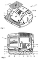
- Fig. 1 shows a perspective view of a thermal transfer postage meter 1 from the front and top right.
- the thermal transfer franking machine 1 is provided at its right side 7 and at its upper part 10 with a flap 5 to the cassette compartment of the franking machine 1 and at its left side with a weighing plate 2 of a scale assembly. All housing parts are made of colored plastic, for example.
- the supply and removal of mailpieces takes place on the feed table 4 of the franking machine on the front side of the franking machine 1 from the left side and to the right side 7.
- Fig. 2 shows a plan view of a thermal transfer franking machine without flap.
- the flap on the front of the top 10 has been removed.
- previously-covered parts such as the left case outer wall 3 near the cassette tray on the left side near the weighing plate 2 and the cassette-receiving mechanism left-side cover 30, the thermal transfer ribbon cassette 8 with a lock member 11 for accurately positioning the cassette 8 in FIG a lock position and with a pressing member 12 for the contact force impressing cassette 8, the thermal transfer printing head 9, the right-side cassette-receiving mechanism cover 60, and the right-hand housing outer wall 6 near the right-side cassette 7 of the thermal transfer postage meter.
- the left-side cover 30 and right-side cover 60 each have a slot-shaped opening 31 and 61 for the left and for the right flap arm of the - 5 - not shown.
- On the cover 30 for the left-side mechanism of the cartridge holder there is mounted a damper 59 for decelerating the shutter opening speed of the cartridge door. Thereby, external access to the chip reading unit is prevented for a sufficiently long time, and the power supply of the chip reading unit can be turned off at this time.
- the aforementioned Parts - except locking element 11 and pressure element 12 - are connected to the upper part 10 and belong to the housing upper shell.
- the feed table 4 belongs to the housing lower shell of the thermal transfer franking machine. Both, upper housing shell and lower housing shell are advantageously produced by injection molding.
- the cassette flap 5 has in a recess 56 a trough 57 corresponding to the size of the pressure element 12, which (not visible) exerts a pressing force on the chip.
- a flap finger 53 and protrusions 541, 542 are disposed between both flap arms 51 and 52.
- the left flap arm 52 is formed as a gear segment to cooperate with the gear of the damping element (not shown).
- On both flap arms 51 and 52 are each a bearing pin 511, 521 formed for a rotatable in the axis 55 connection (not shown) with the housing upper shell.
- a spring 58 is arranged, which opposes the closing of the flap 5, a spring force.
- the cassette flap 5 is also advantageously produced by injection molding. If the ribbon cassette 8 has not been inserted correctly by the operator, the elevations 542, 542 on the underside of the cassette flap 5 force the ribbon cassette 8 into the locking position at the latest when closing the cassette flap 5.
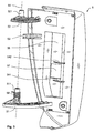
- FIG. 4 shows a perspective view from the front and the top right of a thermal transfer franking machine 1 with the flap 5 open.
- the flap 5 is shown unfolded in the direction of the upper part 10.
- the flap 5 has on its underside both sides arranged flap arms 51, 52.
- the right housing outer wall 6 on the cassette compartment is on the one hand on the right side 7 in the right side wall of the upper shell of the postage meter and on the other hand in the right cover 60 over, with an upward first Graduation 62 is formed, which corresponds to the valve shape on the underside.
- the left Housing outer wall 3 on the cassette compartment merges into the upper shell of the postage meter machine and into the left-hand cover 30, wherein an upward second graduation 32 is formed, which corresponds to the shape of the flap on its underside and accommodates the damping element 59 on the step.
- the damping element 59 consists of a brake drum and a gear, which engages with the gear segment of the left flap arm 52.
- the arms 51, 52 of the cassette flap 5 dive when closing the flap in the corresponding slot-shaped opening 31 and 61 in the steps 32 and 62 of the left and right cover 30 and 60 a.
- the flap 5 has on its underside also a flap finger 53 as actuating means for a Mecha-nismus acting on a sensor (not visible), which detects the position of the flap. Even when lifting the flap leading edge by a few millimeters (about 10-20 mm stroke), there is a shutdown of the supply voltage, ie before access to the chip reading unit or the removal of the cassette is possible.
- a correctly inserted ribbon cassette 8 is accurately positioned by a resiliently disposed on the cassette tray member 17 locking element 11.
- the ink ribbon cassette 8 is held by the pressure element 12 in a locking position, wherein the pressure element 12 at the top of the locking element 11 (not visible) is arranged and a secure impressing a sufficient contact force on the chip of the ink ribbon cassette 8 causes.
- a chip reading unit (hidden) is disposed on the housing back wall 173 of the cassette compartment 17 in an opening.
- the cassette compartment is laterally bounded on both sides by a right inner housing wall 171 and left inner housing wall 172.
- the left housing inner wall 172 has an opening 18 for the friction wheel 38, which is lifted in the illustration of Figure 4, ie with the door open 5, from the ribbon cassette.
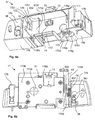
- FIG. 5a shows the perspective view of the cassette compartment molding from the front lower right.
- the housing upper shell mechanism is supported - in a manner not shown - between the left and right housing inner wall 172 and 171 and the left and right Gepuraussenwand on cassette compartment molding 17 on the chassis while associated sensors on each molded sensor carrier 174 and 175th support.
- the cassette flap position / encoder position sensor 36 is supported on the sensor tray 174 of the cassette tray molding 17 externally molded on the left housing inner wall 172.
- the interior (cassette tray) of the cassette tray molding 17 is defined by the right housing inner wall 171, the left housing inner wall 172, and the rear housing wall 173 limited.
- a formation 1731 at the edge between the left housing inner wall 172 and the inside of the housing rear wall 173 forms an outer wall of a channel 1734 for a slider, of which only its roof slope 434 is visible.
- a square opening 1732 in the housing back wall 173 accommodates the chip reading unit 14.
- a circular opening 1733 in the housing rear wall 173 is provided for the - not shown - Aufwickeldorn the cassette spool.
- the left housing inner wall 172 has an opening 18 and lateral guide means 1721 for correctly positioning the cassette during insertion.
- the right inner housing wall 172 also has lateral guide means.
- An upper housing wall 176 also has guide means 1761, 1762 as a positioning aid.
- the upper housing wall 176 merges laterally into the left and right housing inner walls and back into the housing rear wall 173 and not only stabilizes the cassette compartment, but also has molded fastening means (concealed) for the resilient locking element 11, at the free end of the pressure element 12 is formed ,
- a protruding into the interior of the cassette compartment frame 177 for the print head is integrally formed at the lower end of the housing rear wall 173 in the center.
- the space enclosed by the laterally molded-on sensor carriers 174 and 175, respectively, is closed at the bottom by a respective bottom plate 178, 179, which are respectively formed on the housing rear wall 173 between the left and right housing inner walls 172 and 171.
- the bottom plate 178 rises slightly outwardly of the feed table and terminates downstream in a thickened edge 1781 in front of the printhead frame 177.
- the bottom plate 179 behind the frame 177 begins with a thickening 1791, which receives idle rollers 1792 and 1792 and rotatably supports.
- FIG. 5 b shows the rear view of the cassette compartment molding with a channel-shaped formation 1734 on its outer wall 1730.
- the channel 1734 has a guide groove 1735 in the center for the rail 432 and nose 4331 on the front side of the slider 43.
- a force can be exerted by the compression spring 44 via the slider 43 on the - not shown - mechanism (Encoderradhalter).
- the mechanism via the slider 43 is movable by a first on the slider 43 effective spring force F 1 .
- a compression spring 44 is arranged on the slider 43 so that when the cassette door 5 is opened, the compression spring 44 is released and the first spring force F 1 is effectively exerted on the mechanism.
- the slider 43 is movably arranged between the cassette compartment molding 17 and the chassis in the channel 1734 of the cassette compartment molding 17 and is displaced upward in the illustration of FIG. 5b. He has a roof slope 434 for its operation against the force of the compression spring 44.
- the slider 43 has an operating slope 437 for the located under the cover and gradations of the housing upper shell mechanism is supported on the chassis. Its operation is triggered by changing the cassette flap position and detected by the sensor 36, which is supported on the externally molded on the left housing inner wall 172 sensor carrier 174 of the cassette tray molding 17 and a sensor actuating lever 361, which is brought into engagement with the mechanism.
- the other sensor carrier 175 of the cassette tray molding 17 may also include a sensor to detect the ejection of mailpieces.
- the back side 1730 of the housing rear wall 173 of the cassette compartment molding 17 has fastening means 1763 for the resilient locking element 11 arranged on the upper housing wall 176.
- the rear side 1730 of the housing rear wall 173 of the cassette compartment molding part 17 shows the continuous circular opening 1733 and a printed circuit board 13 which enables the electrical connection and mechanical fastening of the chip silent unit.
- the cassette compartment molding 17 is advantageously produced by injection molding.
- Fig. 6 shows details of the mechanism which is arranged to the left of the cassette compartment below the left cover 30.
- the mechanism includes an encoder wheel holder rotatably mounted on the chassis about a pivot axis 39.
- the slider is force connected to the encoder wheel holder, which is movable against a second spring force.
- the slide between the chassis, not shown, and channel outer wall 1731 thus serves with open flap for transmitting power to the Encoderradhalter whose rocker 333 is rotatably mounted about the axis 39, the latter being arranged transversely to the mail piece transport direction.
- a force F is exerted by the flap finger on the roof slope 434 of the slider.
- the slider is - as shown in the illustration of Figure 6 - shifted down and can thus exert no force on the Encoderradhalter.
- a tension spring 37 is attached near the left outer casing wall on the cassette compartment molding 17 and also arranged on the Encoderradhalter 33 accordingly, that when an opening of the cassette flap 5 takes place, the tension spring 37 is tensioned, wherein the second spring force F 2 is effectively exerted on the mechanism ,
- the sensor actuator itself has a spring and is in this embodiment a resilient rotatably mounted sensor actuating lever 361.
- a crank 3347 is raised at the end of a fourth rocker 334 of the encoder wheel holder from the level of the feed table, whereby the sensor actuating lever 361 is pressed.
- the sensor operating lever 361 performs a rotational movement about one Axle 360 and it arrives at the other end of the sensor actuating lever 361 integrally formed flag 362 out of the detection range of the sensor electronics of the sensor electronics housing 363.
- a friction wheel 38 is pressed through an opening 18 in the left housing inner wall 172 and through a side window opening of the ribbon cassette to the ribbon ,
- the friction wheel 38 is rigidly coupled to an encoder wheel (not shown) via a common bearing pin 34 mounted in at least one rocker 333. Ribbon transport results in a rotary motion which is transmitted to the encoder wheel and detected by an encoder (not shown).
- FIG. 7 shows a sensor 36 for detecting the cassette flap position or the encoder position in a perspective view from the front, at the very top.
- a spring 364 holds the sensor actuation lever 361 in the position shown when it is not actuated. The latter is the case when the cassette door is opened.
- the spring 364 is designed for example as a torsion spring, whose one spring leg bears in a hole 3611 of the sensor actuating lever 361 and whose other spring leg is supported on the sensor electronics housing 363.
- the sensor electronics includes, for example, a light barrier, which - in the position shown - is interrupted by the integrally formed on the lever flag 362.
- a photointerrupter LG-413L sensor from Kodenshi Corp. is used. for use.
- the friction wheel 38 performs a sufficiently large pivotal movement, which also operates the sensor actuating lever 361, which has corresponding dimensions due to its lever length between the axis 360 and the outermost end.
- FIG. 8 a shows a front view
- FIG. 8 b shows a side view of the slider, which allows the pivoting movement and serves to transmit power to the encoder wheel holder when the flap is opened.
- a compression spring 44 pushes the slider 43 with a predetermined Force up and shifts the axis 34 of the encoder wheel 33 in a slot of the chassis 40, wherein the encoder position changes so far that the friction wheel 38 is no longer in contact with the cassette ribbon.
- no force F is exerted by flap fingers on the sloping roof 434 of the slider flat body.
- the slider flat body 431 has a flat smooth back and at least one rail 432 for guiding on its front side, which is continuously formed in the direction of movement.
- a second narrow guide rail 4311 may be formed on the front side of the slider flat body 431. It is bounded at its upper end by the roof slope 434 and at its lower end by a hollow cylinder, which are formed curved forward.
- the wall 436 of the hollow cylinder has a mounting opening 438 for a compression spring 44.
- Either a roof 435 of the hollow cylinder or an operating slope 437 of the slider flat body can engage with the cassette door open with at least a portion of the located behind the left cover 30 of the housing upper shell mechanism.
- the slider flat body 431 has between its center and its lower end a tuning fork-shaped opening 439 for a snap-in spring part 433 in the middle of the tuning fork-shaped opening 439.
- the snap-in spring part 433 is guided and prevented with its nose 4331 in the guide groove 1735 pulling out the slider 43 from the channel in the assembled state, as shown in Fig. 5b.
- FIG. 9 shows a chip-type thermal transfer ribbon cassette in a perspective view from the rear left upper corner.
- the thermal transfer ribbon is visible in a lower first opening 88 and in a second opening 85 of the left side wall 83 of the housing of the thermal transfer ribbon cassette.
- FIG. 10 shows a perspective view from the front left upper side of the feed table and the chassis of the franking machine. The perspective view also shows the relative position of mechanical and electrical means to the feed table 4 and to the chassis 40, the aforesaid means, such as the locking element 11 with the pressure element 12, the circuit board 13 with the chip reading unit 14, the undriven ones involved in the ejection Rollers 1792 and 1793, the sensor 36 and the slider 43 are all am- - shown in the Fig. 5a, 5b - cartridge compartment molding attached.
- the position of the locking element 11 with the pressure element 12 relative to the thermal transfer print head 9 corresponds to the required height resulting from the height H of the cassette 8.
- the thermal transfer printhead 9 is attached to the chassis 40 and protrudes into the postal path.
- the slider 43 is disposed between the chassis 40 and the cassette tray molding post-upstream of the thermal transfer print head 9.
- a mechanism is arranged post upstream of the slider 43 and rotatably mounted on the chassis 40 about a rotation axis 39.
- the mechanism comprises an incorporated in the chassis 40 elongated guide opening 46 for a bearing pin 34 for Encoderrad 35 and friction wheel 38, a Encoderradhalter 33 of a nose 3336 for attachment of one end of a tension spring (not shown) and mounted on the chassis 40 Abstandstorso 47, the a neck 471 with head 472 for attachment of the other end of the tension spring (not shown).
- the force effect of the - not shown - tension spring causes the bearing shown in Figure 10 of the bearing pin 34 at one end in the elongated guide opening 46.
- the operating slope 437 of the slider 43 abuts the bearing pin 34 to move the latter in the elongated guide opening 46 can when the cassette door 5 is open.
- the force of the compression spring (not shown) of the slider is stronger than that of the tension spring and causes - not shown - a bearing of the bearing pin 34 at the other end in the elongated guide opening 46.
- the compression spring is tensioned when closing the cassette flap 5 by their fingers 53 presses on the roof slope 434, as already explained with reference to FIG. 8b.
- a circular opening 48 in the chassis 40 is provided for a winding mandrel (not shown) post-downstream of the thermal transfer printhead 9.
- the feed table 4 has at the outlet of the postal path on a rectangular opening 45 which is provided for a driven ejection roller 15, which are opposed to the ejection of the mail pieces undriven rollers 1792, 1793 of the cassette compartment molding.
- Fig. 11 shows a perspective view of a Encoderradhalters from the front left above.
- First and third rocker arms 331 and 333 of the encoder wheel holder 33 have bearing holes 3315 and 3335 for a bearing pin 34 (not shown) via which the encoder wheel 35 (not shown) and the friction wheel 38 (not shown) are rigidly connected.
- a second and fourth rocker 332 and 334 of the Encoderradhalters 33 have bearing openings 3325 and 3345 for the (dash-dotted lines shown) axis of rotation 39.
- One end of the tension spring 37 is connected to one end 3336 of the third rocker 333 of the Encoderradhalters 33.
- a crank piece 3347 is arranged at the end 3346 of the third rocker 334 of the encoder wheel holder 33, which faces away from the axis of rotation 39.
- the first and second rocker 331 and 332 are spaced apart by a connector 335. Between the other adjacent wings connectors are also formed.
- Fig. 12 is a side view and in Fig. 13 is a front view of the feed table and chassis of the postage meter in the state of a closed (not shown) flap shown.
- the mechanism according to the invention consists of the spacer stub 47 fastened to the chassis 40, the oblong opening (not visible) incorporated in the chassis 40 and the encoder wheel holder 33, which is mounted on the chassis 40 fixed rotational axis 39 is rotatable and actuates a sensor 36 and carries the bearing pin 34 for the encoder wheel 35 and friction wheel 38, wherein the position of the bearing pin 34 from the slider 43 due to the spring force F 1 of a compression spring 44 against the spring force F 2 a between the on the chassis 40th fortified Abstandstorso 47 and the Encoderradhalter 33 tensioned tension spring 37 is changed as soon as the flap is opened and thus the force F decreases.
- the compression spring 44 When closing of the cassette door 5 occurs, the compression spring 44 is cocked, since F 2 ⁇ F 1 ⁇ F.
- the friction wheel 38 of the cassette compartment molding then engages in the manner shown in Figure 5a via the opening 18 with inserted cassette with the thermal transfer ribbon in engagement.
- the bearing pins 34, pivot axis 39, spacer torso 47 and the chassis 40 are advantageously made of metal and the locking element 11, tension spring 37, compression spring 44, torsion spring 364 are made of spring steel.
- the torsion spring 364 exerts a third force effect F 3 via the sensor actuating lever 361 on the crank piece 3347 of the sprung encoder wheel holder 33, where: F 3 ⁇ F 2 .
- the encoder wheel 33 is advantageously produced by injection molding of plastic or metal. The invention should not be understood as being limited to the illustrated preferred embodiment.
- the encoder wheel holder 33, the bearing pin 34 and rotation axis 39 may have a different shape. For example, these are bent like a paper clip from a piece of wire. Then carries a instead of the bearing pin 34 on the piece of wire plugged hollow shaft the encoder wheel 35 and friction wheel 38. Accordingly, the arrangement of the tension and / or compression springs can vary.
- the sensor actuator is a resilient rotatably mounted sensor actuation lever 361.
- a toothed wheel can be arranged on the sensor 36 on the axis of rotation 360, which is in engagement with a further toothed wheel arranged on the axis of rotation 39.
- the torsion spring 364 can then be omitted.
- another slide can serve as a sensor actuator.
Landscapes
- Physics & Mathematics (AREA)
- General Physics & Mathematics (AREA)
- Devices For Checking Fares Or Tickets At Control Points (AREA)
- Electronic Switches (AREA)
- Sorting Of Articles (AREA)
- Facsimiles In General (AREA)
Applications Claiming Priority (1)
| Application Number | Priority Date | Filing Date | Title |
|---|---|---|---|
| DE202004015278U DE202004015278U1 (de) | 2004-10-01 | 2004-10-01 | Kassettenaufnahmeeinrichtung mit Zustandserkennung für ein druckendes Postverarbeitungsgerät |
Publications (3)
| Publication Number | Publication Date |
|---|---|
| EP1643456A1 true EP1643456A1 (fr) | 2006-04-05 |
| EP1643456B1 EP1643456B1 (fr) | 2008-06-11 |
| EP1643456B9 EP1643456B9 (fr) | 2009-09-23 |
Family
ID=33522035
Family Applications (1)
| Application Number | Title | Priority Date | Filing Date |
|---|---|---|---|
| EP05020747A Expired - Lifetime EP1643456B9 (fr) | 2004-10-01 | 2005-09-23 | Compartiment à cassettes avec détection de l'état pour une machine à affranchir |
Country Status (4)
| Country | Link |
|---|---|
| US (1) | US7410316B2 (fr) |
| EP (1) | EP1643456B9 (fr) |
| AT (1) | ATE398315T1 (fr) |
| DE (2) | DE202004015278U1 (fr) |
Families Citing this family (4)
| Publication number | Priority date | Publication date | Assignee | Title |
|---|---|---|---|---|
| ITGE20060081A1 (it) * | 2006-08-03 | 2008-02-04 | Grafoplast Spa | Dispositivo automatico di carico/scarico di supporti di stampa in una macchina da stampa. |
| DE102007060733A1 (de) * | 2007-12-17 | 2009-06-25 | Francotyp-Postalia Gmbh | Vorrichtung zum Wechseln von Tintenkartuschen |
| DE202010015352U1 (de) | 2010-11-11 | 2011-02-10 | Francotyp-Postalia Gmbh | Verschlussvorrichtung |
| AU360787S (en) * | 2014-10-18 | 2015-03-24 | Francotyp Postalia Gmbh | Franking machine |
Citations (5)
| Publication number | Priority date | Publication date | Assignee | Title |
|---|---|---|---|---|
| US4899172A (en) * | 1987-12-28 | 1990-02-06 | Pitney Bowes Inc. | Method and apparatus for perforating indicia on used thermal transfer ribbon within a cassette |
| US5486973A (en) * | 1993-09-24 | 1996-01-23 | Neopost Industrie | Postage meter including a safety locking circuit |
| US5746133A (en) * | 1995-05-22 | 1998-05-05 | Ascom Hasler Mailing Systems Ag | Postage meter with rotor movement and die cover sensor |
| EP0875865A2 (fr) * | 1997-05-02 | 1998-11-04 | Neopost Limited | Machine à affranchir ayant une tête d'impression amovible |
| DE19958946A1 (de) * | 1999-11-26 | 2001-06-21 | Francotyp Postalia Gmbh | Verfahren zum Piraterieschutz eines Gerätes und Anordnung zur Durchführung des Verfahrens |
Family Cites Families (6)
| Publication number | Priority date | Publication date | Assignee | Title |
|---|---|---|---|---|
| GB9621378D0 (en) * | 1996-10-14 | 1996-12-04 | Esselte Nv | Tape printing apparatus |
| DE19958941B4 (de) | 1999-11-26 | 2006-11-09 | Francotyp-Postalia Gmbh | Verfahren zum Schutz eines Gerätes vor einem Betreiben mit unzulässigem Verbrauchsmaterial |
| EP1607912B1 (fr) | 2001-10-02 | 2013-03-20 | Francotyp-Postalia GmbH | Procédé et dispositif pour l'ouverture d'un boîtier sécurisé |
| JP2003285492A (ja) * | 2002-03-27 | 2003-10-07 | Brother Ind Ltd | 印刷装置 |
| US20030197770A1 (en) * | 2002-04-19 | 2003-10-23 | Klinefelter Gary M. | Card cartridge and card feed adapter for an ink jet sheet feeder printer |
| GB0230196D0 (en) * | 2002-12-24 | 2003-02-05 | Esselte Nv | Identifying compatible combination for a thermal printer |
-
2004
- 2004-10-01 DE DE202004015278U patent/DE202004015278U1/de not_active Expired - Lifetime
-
2005
- 2005-09-09 US US11/222,877 patent/US7410316B2/en not_active Expired - Fee Related
- 2005-09-23 EP EP05020747A patent/EP1643456B9/fr not_active Expired - Lifetime
- 2005-09-23 AT AT05020747T patent/ATE398315T1/de active
- 2005-09-23 DE DE502005004383T patent/DE502005004383D1/de not_active Expired - Lifetime
Patent Citations (5)
| Publication number | Priority date | Publication date | Assignee | Title |
|---|---|---|---|---|
| US4899172A (en) * | 1987-12-28 | 1990-02-06 | Pitney Bowes Inc. | Method and apparatus for perforating indicia on used thermal transfer ribbon within a cassette |
| US5486973A (en) * | 1993-09-24 | 1996-01-23 | Neopost Industrie | Postage meter including a safety locking circuit |
| US5746133A (en) * | 1995-05-22 | 1998-05-05 | Ascom Hasler Mailing Systems Ag | Postage meter with rotor movement and die cover sensor |
| EP0875865A2 (fr) * | 1997-05-02 | 1998-11-04 | Neopost Limited | Machine à affranchir ayant une tête d'impression amovible |
| DE19958946A1 (de) * | 1999-11-26 | 2001-06-21 | Francotyp Postalia Gmbh | Verfahren zum Piraterieschutz eines Gerätes und Anordnung zur Durchführung des Verfahrens |
Also Published As
| Publication number | Publication date |
|---|---|
| EP1643456B9 (fr) | 2009-09-23 |
| US20060074818A1 (en) | 2006-04-06 |
| DE502005004383D1 (de) | 2008-07-24 |
| DE202004015278U1 (de) | 2004-12-16 |
| US7410316B2 (en) | 2008-08-12 |
| ATE398315T1 (de) | 2008-07-15 |
| EP1643456B1 (fr) | 2008-06-11 |
Similar Documents
| Publication | Publication Date | Title |
|---|---|---|
| DE69115132T2 (de) | Automatischer Postschalter. | |
| DE69017605T2 (de) | Ablagevorrichtung für Briefumschläge und Einzelblätter. | |
| DE69826203T2 (de) | Drucker | |
| DE69129909T2 (de) | Aufzeichnungsgerät zur Durchführung einer Aufzeichnung mittels eines Tintenstrahlaufzeichnungskopfes | |
| EP1103928B1 (fr) | Tachygraphe avec un dispositif d'impression | |
| EP0143250A1 (fr) | Dispositif d'écriture à encre à tête d'écriture interchangeable | |
| DE3544923A1 (de) | Farbbandkassette | |
| EP2073173B1 (fr) | Dispositif destiné à changer des cartouches d'encre | |
| EP0794066A1 (fr) | Mécanisme indiquant la présence d'un ruban dans un appareil d'impression de bande | |
| EP1300807B1 (fr) | Procédé et dispositif pour l'ouverture d'un boítier sécurisé | |
| EP1643456B9 (fr) | Compartiment à cassettes avec détection de l'état pour une machine à affranchir | |
| DE3516460A1 (de) | Einrichtung zur voruebergehenden speicherung von belegen | |
| DE69418130T2 (de) | Vorrichtung zum Abtasten der Oberflächenkontur von Poststücken | |
| EP0750277B1 (fr) | Dispositif pour une machine à affranchir électronique à main | |
| DE10164527A1 (de) | Anordnung zum Schutz eines Druckmoduls in einem Postverarbeitungsgerät | |
| DE19517375A1 (de) | Thermodrucker | |
| DE68921593T2 (de) | Verriegelungsvorrichtung für abnehmbare Frankiermaschine. | |
| DE69903589T2 (de) | Bilderzeugungsgerät | |
| EP2597624A1 (fr) | Agencement destiné à l'impression de supports d'impression en forme de bandes | |
| DE10109882C1 (de) | Vorrichtung zum Bedrucken eines Bandstreifens oder von auf einem Bandstreifen haftenden Etiketten | |
| DE69112997T2 (de) | Postmaschine mit einer Vorrichtung zum Führen von Poststücken. | |
| EP0484055B1 (fr) | Dispositif de blocage pour machine d'affranchissement amovible | |
| EP0961236B1 (fr) | Dispositif d'impression de courrier | |
| DE19533540C2 (de) | Vorlagenlese-Bestätigungsmechanismus | |
| EP2153414A1 (fr) | Tachygraphe |
Legal Events
| Date | Code | Title | Description |
|---|---|---|---|
| PUAI | Public reference made under article 153(3) epc to a published international application that has entered the european phase |
Free format text: ORIGINAL CODE: 0009012 |
|
| AK | Designated contracting states |
Kind code of ref document: A1 Designated state(s): AT BE BG CH CY CZ DE DK EE ES FI FR GB GR HU IE IS IT LI LT LU LV MC NL PL PT RO SE SI SK TR |
|
| AX | Request for extension of the european patent |
Extension state: AL BA HR MK YU |
|
| 17P | Request for examination filed |
Effective date: 20060510 |
|
| AKX | Designation fees paid |
Designated state(s): AT BE BG CH CY CZ DE DK EE ES FI FR GB GR HU IE IS IT LI LT LU LV MC NL PL PT RO SE SI SK TR |
|
| GRAP | Despatch of communication of intention to grant a patent |
Free format text: ORIGINAL CODE: EPIDOSNIGR1 |
|
| GRAS | Grant fee paid |
Free format text: ORIGINAL CODE: EPIDOSNIGR3 |
|
| GRAA | (expected) grant |
Free format text: ORIGINAL CODE: 0009210 |
|
| AK | Designated contracting states |
Kind code of ref document: B1 Designated state(s): AT BE BG CH CY CZ DE DK EE ES FI FR GB GR HU IE IS IT LI LT LU LV MC NL PL PT RO SE SI SK TR |
|
| REG | Reference to a national code |
Ref country code: GB Ref legal event code: FG4D Free format text: NOT ENGLISH |
|
| REG | Reference to a national code |
Ref country code: CH Ref legal event code: EP |
|
| REF | Corresponds to: |
Ref document number: 502005004383 Country of ref document: DE Date of ref document: 20080724 Kind code of ref document: P |
|
| REG | Reference to a national code |
Ref country code: IE Ref legal event code: FG4D Free format text: LANGUAGE OF EP DOCUMENT: GERMAN |
|
| PG25 | Lapsed in a contracting state [announced via postgrant information from national office to epo] |
Ref country code: SI Free format text: LAPSE BECAUSE OF FAILURE TO SUBMIT A TRANSLATION OF THE DESCRIPTION OR TO PAY THE FEE WITHIN THE PRESCRIBED TIME-LIMIT Effective date: 20080611 Ref country code: FI Free format text: LAPSE BECAUSE OF FAILURE TO SUBMIT A TRANSLATION OF THE DESCRIPTION OR TO PAY THE FEE WITHIN THE PRESCRIBED TIME-LIMIT Effective date: 20080611 |
|
| PG25 | Lapsed in a contracting state [announced via postgrant information from national office to epo] |
Ref country code: PL Free format text: LAPSE BECAUSE OF FAILURE TO SUBMIT A TRANSLATION OF THE DESCRIPTION OR TO PAY THE FEE WITHIN THE PRESCRIBED TIME-LIMIT Effective date: 20080611 Ref country code: LV Free format text: LAPSE BECAUSE OF FAILURE TO SUBMIT A TRANSLATION OF THE DESCRIPTION OR TO PAY THE FEE WITHIN THE PRESCRIBED TIME-LIMIT Effective date: 20080611 |
|
| PG25 | Lapsed in a contracting state [announced via postgrant information from national office to epo] |
Ref country code: ES Free format text: LAPSE BECAUSE OF FAILURE TO SUBMIT A TRANSLATION OF THE DESCRIPTION OR TO PAY THE FEE WITHIN THE PRESCRIBED TIME-LIMIT Effective date: 20080922 Ref country code: LT Free format text: LAPSE BECAUSE OF FAILURE TO SUBMIT A TRANSLATION OF THE DESCRIPTION OR TO PAY THE FEE WITHIN THE PRESCRIBED TIME-LIMIT Effective date: 20080611 Ref country code: PT Free format text: LAPSE BECAUSE OF FAILURE TO SUBMIT A TRANSLATION OF THE DESCRIPTION OR TO PAY THE FEE WITHIN THE PRESCRIBED TIME-LIMIT Effective date: 20081111 Ref country code: SE Free format text: LAPSE BECAUSE OF FAILURE TO SUBMIT A TRANSLATION OF THE DESCRIPTION OR TO PAY THE FEE WITHIN THE PRESCRIBED TIME-LIMIT Effective date: 20080911 Ref country code: IS Free format text: LAPSE BECAUSE OF FAILURE TO SUBMIT A TRANSLATION OF THE DESCRIPTION OR TO PAY THE FEE WITHIN THE PRESCRIBED TIME-LIMIT Effective date: 20081011 Ref country code: CZ Free format text: LAPSE BECAUSE OF FAILURE TO SUBMIT A TRANSLATION OF THE DESCRIPTION OR TO PAY THE FEE WITHIN THE PRESCRIBED TIME-LIMIT Effective date: 20080611 |
|
| REG | Reference to a national code |
Ref country code: IE Ref legal event code: FD4D |
|
| PG25 | Lapsed in a contracting state [announced via postgrant information from national office to epo] |
Ref country code: RO Free format text: LAPSE BECAUSE OF FAILURE TO SUBMIT A TRANSLATION OF THE DESCRIPTION OR TO PAY THE FEE WITHIN THE PRESCRIBED TIME-LIMIT Effective date: 20080611 Ref country code: SK Free format text: LAPSE BECAUSE OF FAILURE TO SUBMIT A TRANSLATION OF THE DESCRIPTION OR TO PAY THE FEE WITHIN THE PRESCRIBED TIME-LIMIT Effective date: 20080611 |
|
| BERE | Be: lapsed |
Owner name: FRANCOTYP-POSTALIA G.M.B.H. Effective date: 20080930 |
|
| PLBE | No opposition filed within time limit |
Free format text: ORIGINAL CODE: 0009261 |
|
| STAA | Information on the status of an ep patent application or granted ep patent |
Free format text: STATUS: NO OPPOSITION FILED WITHIN TIME LIMIT |
|
| PG25 | Lapsed in a contracting state [announced via postgrant information from national office to epo] |
Ref country code: MC Free format text: LAPSE BECAUSE OF NON-PAYMENT OF DUE FEES Effective date: 20080930 Ref country code: EE Free format text: LAPSE BECAUSE OF FAILURE TO SUBMIT A TRANSLATION OF THE DESCRIPTION OR TO PAY THE FEE WITHIN THE PRESCRIBED TIME-LIMIT Effective date: 20080611 Ref country code: IE Free format text: LAPSE BECAUSE OF FAILURE TO SUBMIT A TRANSLATION OF THE DESCRIPTION OR TO PAY THE FEE WITHIN THE PRESCRIBED TIME-LIMIT Effective date: 20080611 Ref country code: DK Free format text: LAPSE BECAUSE OF FAILURE TO SUBMIT A TRANSLATION OF THE DESCRIPTION OR TO PAY THE FEE WITHIN THE PRESCRIBED TIME-LIMIT Effective date: 20080611 Ref country code: BG Free format text: LAPSE BECAUSE OF FAILURE TO SUBMIT A TRANSLATION OF THE DESCRIPTION OR TO PAY THE FEE WITHIN THE PRESCRIBED TIME-LIMIT Effective date: 20080911 |
|
| 26N | No opposition filed |
Effective date: 20090312 |
|
| PG25 | Lapsed in a contracting state [announced via postgrant information from national office to epo] |
Ref country code: BE Free format text: LAPSE BECAUSE OF NON-PAYMENT OF DUE FEES Effective date: 20080930 |
|
| PG25 | Lapsed in a contracting state [announced via postgrant information from national office to epo] |
Ref country code: HU Free format text: LAPSE BECAUSE OF FAILURE TO SUBMIT A TRANSLATION OF THE DESCRIPTION OR TO PAY THE FEE WITHIN THE PRESCRIBED TIME-LIMIT Effective date: 20081212 Ref country code: LU Free format text: LAPSE BECAUSE OF NON-PAYMENT OF DUE FEES Effective date: 20080923 Ref country code: CY Free format text: LAPSE BECAUSE OF FAILURE TO SUBMIT A TRANSLATION OF THE DESCRIPTION OR TO PAY THE FEE WITHIN THE PRESCRIBED TIME-LIMIT Effective date: 20080611 |
|
| PG25 | Lapsed in a contracting state [announced via postgrant information from national office to epo] |
Ref country code: TR Free format text: LAPSE BECAUSE OF FAILURE TO SUBMIT A TRANSLATION OF THE DESCRIPTION OR TO PAY THE FEE WITHIN THE PRESCRIBED TIME-LIMIT Effective date: 20080611 |
|
| PG25 | Lapsed in a contracting state [announced via postgrant information from national office to epo] |
Ref country code: GR Free format text: LAPSE BECAUSE OF FAILURE TO SUBMIT A TRANSLATION OF THE DESCRIPTION OR TO PAY THE FEE WITHIN THE PRESCRIBED TIME-LIMIT Effective date: 20080912 |
|
| REG | Reference to a national code |
Ref country code: DE Ref legal event code: R084 Ref document number: 502005004383 Country of ref document: DE Effective date: 20130620 Ref country code: GB Ref legal event code: 746 Effective date: 20130722 |
|
| REG | Reference to a national code |
Ref country code: DE Ref legal event code: R081 Ref document number: 502005004383 Country of ref document: DE Owner name: FRANCOTYP-POSTALIA GMBH, DE Free format text: FORMER OWNER: FRANCOTYP-POSTALIA GMBH, 16547 BIRKENWERDER, DE Effective date: 20150330 |
|
| REG | Reference to a national code |
Ref country code: FR Ref legal event code: PLFP Year of fee payment: 12 |
|
| REG | Reference to a national code |
Ref country code: FR Ref legal event code: PLFP Year of fee payment: 13 |
|
| PGFP | Annual fee paid to national office [announced via postgrant information from national office to epo] |
Ref country code: FR Payment date: 20170928 Year of fee payment: 13 Ref country code: GB Payment date: 20170921 Year of fee payment: 13 Ref country code: CH Payment date: 20170921 Year of fee payment: 13 Ref country code: DE Payment date: 20170802 Year of fee payment: 13 |
|
| PGFP | Annual fee paid to national office [announced via postgrant information from national office to epo] |
Ref country code: AT Payment date: 20170922 Year of fee payment: 13 Ref country code: NL Payment date: 20170921 Year of fee payment: 13 |
|
| PGFP | Annual fee paid to national office [announced via postgrant information from national office to epo] |
Ref country code: IT Payment date: 20170926 Year of fee payment: 13 |
|
| REG | Reference to a national code |
Ref country code: DE Ref legal event code: R119 Ref document number: 502005004383 Country of ref document: DE |
|
| REG | Reference to a national code |
Ref country code: CH Ref legal event code: PL |
|
| REG | Reference to a national code |
Ref country code: NL Ref legal event code: MM Effective date: 20181001 |
|
| REG | Reference to a national code |
Ref country code: AT Ref legal event code: MM01 Ref document number: 398315 Country of ref document: AT Kind code of ref document: T Effective date: 20180923 |
|
| GBPC | Gb: european patent ceased through non-payment of renewal fee |
Effective date: 20180923 |
|
| PG25 | Lapsed in a contracting state [announced via postgrant information from national office to epo] |
Ref country code: NL Free format text: LAPSE BECAUSE OF NON-PAYMENT OF DUE FEES Effective date: 20181001 |
|
| PG25 | Lapsed in a contracting state [announced via postgrant information from national office to epo] |
Ref country code: IT Free format text: LAPSE BECAUSE OF NON-PAYMENT OF DUE FEES Effective date: 20180923 Ref country code: DE Free format text: LAPSE BECAUSE OF NON-PAYMENT OF DUE FEES Effective date: 20190402 |
|
| PG25 | Lapsed in a contracting state [announced via postgrant information from national office to epo] |
Ref country code: LI Free format text: LAPSE BECAUSE OF NON-PAYMENT OF DUE FEES Effective date: 20180930 Ref country code: CH Free format text: LAPSE BECAUSE OF NON-PAYMENT OF DUE FEES Effective date: 20180930 Ref country code: FR Free format text: LAPSE BECAUSE OF NON-PAYMENT OF DUE FEES Effective date: 20180930 |
|
| PG25 | Lapsed in a contracting state [announced via postgrant information from national office to epo] |
Ref country code: AT Free format text: LAPSE BECAUSE OF NON-PAYMENT OF DUE FEES Effective date: 20180923 Ref country code: GB Free format text: LAPSE BECAUSE OF NON-PAYMENT OF DUE FEES Effective date: 20180923 |