EP1643531A1 - Herstellungsverfahren für entladungslampen - Google Patents
Herstellungsverfahren für entladungslampen Download PDFInfo
- Publication number
- EP1643531A1 EP1643531A1 EP04723784A EP04723784A EP1643531A1 EP 1643531 A1 EP1643531 A1 EP 1643531A1 EP 04723784 A EP04723784 A EP 04723784A EP 04723784 A EP04723784 A EP 04723784A EP 1643531 A1 EP1643531 A1 EP 1643531A1
- Authority
- EP
- European Patent Office
- Prior art keywords
- electrodes
- electrode assembly
- discharge lamp
- electrode
- discharge
- Prior art date
- Legal status (The legal status is an assumption and is not a legal conclusion. Google has not performed a legal analysis and makes no representation as to the accuracy of the status listed.)
- Withdrawn
Links
Images


Classifications
-
- H—ELECTRICITY
- H01—ELECTRIC ELEMENTS
- H01J—ELECTRIC DISCHARGE TUBES OR DISCHARGE LAMPS
- H01J9/00—Apparatus or processes specially adapted for the manufacture, installation, removal, maintenance of electric discharge tubes, discharge lamps, or parts thereof; Recovery of material from discharge tubes or lamps
- H01J9/02—Manufacture of electrodes or electrode systems
-
- H—ELECTRICITY
- H01—ELECTRIC ELEMENTS
- H01J—ELECTRIC DISCHARGE TUBES OR DISCHARGE LAMPS
- H01J61/00—Gas-discharge or vapour-discharge lamps
- H01J61/02—Details
- H01J61/04—Electrodes; Screens; Shields
- H01J61/06—Main electrodes
- H01J61/073—Main electrodes for high-pressure discharge lamps
- H01J61/0732—Main electrodes for high-pressure discharge lamps characterised by the construction of the electrode
-
- H—ELECTRICITY
- H01—ELECTRIC ELEMENTS
- H01J—ELECTRIC DISCHARGE TUBES OR DISCHARGE LAMPS
- H01J61/00—Gas-discharge or vapour-discharge lamps
- H01J61/84—Lamps with discharge constricted by high pressure
- H01J61/86—Lamps with discharge constricted by high pressure with discharge additionally constricted by close spacing of electrodes, e.g. for optical projection
Definitions
- the present invention relates to a manufacturing method for a discharge lamp, and particularly to a manufacturing method for a short-arc type discharge lamp in which the distance between electrodes is made short to gain a light source that is close to a point light source.
- Japanese laid-open patent publication No. 3330592 discloses a manufacturing method.
- an electrode assembly including an electrode structure, which is to be formed into a pair of electrodes for a discharge lamp is inserted into a discharge-lamp glass bulb including an arc tube part and side tube parts, and the side tube parts are sealed so as to form the arc tube part in which the electrode structure is disposed, and then the pair of the electrodes is formed within the arc tube part by selectively melt-cutting a part of the electrode structure.
- a predetermined position on a tungsten rod, which is included in the electrode assembly is melted by heat using laser irradiation.
- the electrode material is gradually cooled from parts near to the areas where will be formed into bases of the respective electrodes.
- the tungsten rod is cut by the effect of the surface tension (Such a cutting process is called “Youyu Setsudan” (“melt cutting”) or simply called “Yodan” (an abbreviation for "Youyu Setsudan”).
- the pair of the electrodes is formed by performing the laser irradiation twice or less.
- the predetermined position on the electrode assembly is melt-cut and the tip of one of the electrodes is processed so as to be in a semi-sphere shape
- the second laser irradiation the tip of the other one of the electrodes is processed so as to be in the semi-sphere shape.
- the inventors found that it is difficult to control which electrode's tip is to be processed. If it is uncertain which tip is to be processed, it is also uncertain which electrode is to be subjected to the second laser radiation. Therefore, this is a real problem for the manufacturing of the discharge lamp.
- the present invention therefore aims to provide a discharge lamp manufacturing method for forming a pair of electrodes by performing laser irradiation from the outside of the arc tube, thereby melt-cutting the electrode assembly at a predetermined position, wherein the discharge lamp manufacturing method can appropriately control which electrode's tip is to be processed by the first laser irradiation.
- a discharge lamp manufacturing method for inserting an electrode assembly, which includes a rod that is to be formed into a pair of electrodes, into a discharge-lamp glass bulb having an arc tube part and two side tube parts respectively formed at ends of the arc tube part, sealing each side tube part, and melt-cutting a part of the electrode assembly by irradiating the part with a laser beam emitted from outside of the discharge-lamp glass bulb, the manufacturing method comprising: a laser irradiation step of irradiating a predetermined site on the electrode assembly with the laser beam emitted from a direction that forms a predetermined angle ⁇ 1 with a plane that is orthogonal to a longitudinal direction of the electrode assembly, thereby cutting the part of the electrode assembly, and shaping a tip of one of the electrodes that are formed as a result of the cutting, the predetermined angle ⁇ 1 being more than 0°
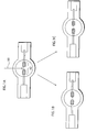
- the inventors of the present invention firstly tried to melt-cut the part of the electrode assembly by horizontally irradiating the part with the laser beam.
- the inventors found that it is impossible to control which electrode' s side the melted electrode material moves toward (see FIG. 1B and FIG.1C).
- the above-described discharge lamp manufacturing method is a result of keen examinations for solving the problem.
- the discharge lamp manufacturing method according to the present invention can appropriately control which electrode's tip is to be processed so as to have a semi-sphere shape, and therefore it is clear which electrode should be subjected to the second laser irradiation.
- the predetermined angle ⁇ 1 is equal to or less than 45 ° .
- the lower limit of the predetermined angle ⁇ 1 is acceptable if it is more than 0°, it is preferable that ⁇ 1 is not less than 5°. If this angle is too large, the shape of a site on the electrode assembly, where is irradiated with the laser beam, becomes an ellipse, and the site might not be heated enough for the melt-cutting, or the lens effect of the glass material included in the arc tube part might have influence on energy efficiency of the laser beam. Therefore, it is preferable that the angle ⁇ 1 is equal to or less than 45°.
- the upper limit of the angle ⁇ 1 depends on the type of the lamp and the shape and the material of the arc tube part. According to the examination performed by the inventors of the present invention, it is preferable that the angle ⁇ 1 is between approximately 5° and approximately 15°.
- a center point of the predetermined site is nearer to the one of the electrodes than a center point C of the electrode assembly within a discharge space is, the discharge space being formed after each side tube part is sealed.
- a center point of the predetermined site By setting a center point of the predetermined site nearer to the one of the electrodes than a center point C of the electrode assembly within a discharge space is, it becomes possible to more surely shaping the tip of the one of the electrodes.
- the center point of the predetermined site is substantially identical with the center point C , it is sometimes impossible to properly process the desired position, maybe because the laser beam has a width.
- an incidence rate of such problem depends on several conditions, such as the structure of the electrode assembly, that is presence or absence of covering materials, which are described later, and the shapes and the positions of the covering materials.
- the discharge lamp manufacturing method may further comprise another laser irradiation step of irradiating the other one of the electrodes with a laser beam, thereby shaping a tip of the other one of the electrodes.
- the present invention is not limited to this, and it is possible to form the electrodes by performing the laser irradiation only once.
- direct-current discharge lamps can be manufactured by performing the laser irradiation only once, from a practical view point. However, presumably, there are many cases where it is preferable to perform the second laser irradiation.
- the second laser irradiation may be performed by irradiating the tip of the electrode with a laser beam at an angle, it is confirmed that the laser irradiationmay be performed by horizontally irradiating the tip as well.
- the number of laser irradiation is not limited to twice, and it may be performed three times or more to arrange the shape of the tip of the electrode.
- the present invention may be the discharge lamp manufacturing method, wherein the electrode assembly is a tungsten rod to which two covering members are attached, the covering members to be respectively fixed to the tips of the electrodes, in the laser irradiation step, the tungsten rod is cut, and a portion of the tungsten rod, which is to be formed into the one of the electrodes, and a part of one of the covering members are melted and integrated together, and the tip of the one of the electrodes is shaped so as to have a semi-sphere shape, and in the another laser irradiation step, a portion of the tungsten rod, where is to be formed into the other one of the electrodes, and a part of the other one of the covering members are melted and integrated together, and the tip of the other one of the electrodes is shaped so as to have a semi-sphere shape.
- the covering members may be in coil shapes. However, the present invention is not limited to this.
- the covering members may be in cylindrical shape.
- D (mm) is a distance between the electrodes in final form, and it is preferable that D is equal to or less than 2mm.
- D is a distance between the electrodes in final form, and it is preferable that D is equal to or less than 2mm.
- FIG.2 to FIG.4 are used for explaining a high-pressure mercury lamp manufacturing method as an example of the discharge lamp manufacturing method according to the present invention.
- a discharge-lamp glass bulb 50 (hereinafter simply called the "glass bulb") and an electrode assembly 40 including an electrode structure 42, which is to be formed as a pair of electrodes, are firstly prepared, and then the electrode assembly is inserted into the glass bulb 50.
- the glass bulb 50 includes an arc tube part 10, which is in a substantially spherical shape and to be formed as an arc tube of the discharge lamp, and side tube parts 22, which are extended from the arc tube part 10. A part of each side tube part becomes a sealing part of the discharge lamp.
- the glass bulb 50 may be held by chucks 52. In this embodiment, the glass bulb 50 is held horizontally. However, the glass bulb 50 may be held vertically.
- the glass bulb 50 is made of silica glass, for instance.
- the arc tube part 10 in the glass bulb 50 used in the embodiment has an inside diameter of 6mm and a thickness of 3mm, and each of the side tube parts 22 has an inside diameter of 3.4mm and a length of 250mm in the longitudinal direction.
- the electrode assembly 40 includes a tungsten rod 16 that constitutes the electrode structure 42, and metal foils 24 and 24'that are respectively connected to both ends of the tungsten rod 16.
- Each of the metal foils 24 and 24' are made of a molybdenum foil, for instance.
- the tungsten rod 16 is to be processed so as to form the electrode rod of each of the pair of the electrodes included in the discharge lamp.
- the length of the tungsten rod 16 is 20mm for instance, and the outside diameter of the tungsten rod 16 is 0.4mm for instance.
- a melt-cut part 18 is in the middle of the tungsten rod 16, which is to be melt-cut in a later step. Both outside ends of the melt-cut part 18 are to be processed so as to form the tips of the electrodes.
- coils 14 and 14' as covering members are attached to those outside ends.
- the distance between the tips of the coils is approximately 1mm to 1.5mm. In this case, the distance D between the electrodes in final form becomes approximately 1mm.
- each of the coils 14 and 14' is formed so that the inside diameter of each coil at the time it is wound up becomes shorter than the diameter of the tungsten rod 16, and the tungsten rod 16 is press-fitted into the coils.
- the coils 14 and 14' wind around the tungsten rod 16 evenly, and when the melt-cut part is melt-cut by the laser irradiation, for instance, in a later step, the amount of the heat radiated from each coil becomes homogeneous.
- the tungsten rod 16 may be attached to the coils by resistance welding after it is inserted into the coils 14 and 14' that have larger inside diameters.
- each of the coils 14 and 14' has a function to prevent the tips of the electrodes from being overheated when the produced discharge lamp is lit up. Therefore, the shapes of the covering members are not limited to the coil shapes.
- the covering members may have cylindrical shapes. Note that the outside diameter of each of the parts where the coils 14 and 14' are attached is approximately 1.4mm for instance.
- the electrode structure, which is to be formed into the pair of electrodes is constituted of the one tungsten rod 16. Therefore, the central axes of the pair of the electrodes are naturally the same.
- the tungsten rod 16 and the metal foil 24, and the tungsten rod 16 and the metal foil 24' are connected to each other by welding.
- the metal foils 24 and 24' are rectangular flat plates, and the sizes thereof may be adjusted according to requirements. Note that the other ends of the metal foils, which are not connected to the tungsten rod 16, are connected, by welding, with external leads 30 made of molybdenum.
- the electrode assembly 40 is inserted into the glass bulb 50 so that the electrode structure 42 is positioned within the arc tube part 10 of the glass bulb 50.
- the sealing parts 20 and 20' of the discharge lamp are formed by closely attaching the side tube parts 22 of the glass bulb 50 to parts (the metal foils 24 and 24') of the electrode assembly 40.
- the side tube parts 22 are closely attached (sealed) to the metal foils 24 and 24' by a method in public domain. For instance, after the state of the glass bulb 50 is made ready for reducing the pressure within the glass bulb, the pressure within the glass bulb 50 is reduced (e. g. 20kPa).
- the sealing part 20 is formable by closely attaching one of the side tube parts 22 and the metal foil 24, by heating and softening the side tubes 22 of the glass bulb 50 with use of a burner under the reduced pressure while rotating the glass bulb 50 with use of the chucks 52.
- the arc tube part 10 encloses therein amercury 118 as the light-emittingmaterial (e.g. 150-200mg/cm 3 ), a rare gas at 5-20kPa (e.g. argon), and a small amount of halogen (e.g. bromine).
- the halogen is not limited to an elementary substance (e.g. Br 2 ), and may be enclosed in the form of a halogen precursor. In this embodiment, the bromine is enclosed in the form of CH 2 Br 2 .
- the enclosed halogen (or the halogen induced from the halogen precursor) has a function for performing the process of a halogen cycle while the discharge lamp is operating.
- a pair of electrodes 12 and 12' having predetermined distance D therebetween is obtainable by selectively cutting the melt-cut part 18 disposed within the arc tube part 10.
- the tips of the electrodes 12 and 12' are processed so as to be in the semi-sphere shape by the laser irradiation from outside as described later.
- the discharge lamp 100 in which the pair of the electrodes 12 and 12' are formed within the arc tube part 10, is obtainable.
- the manufacturing method for the discharge lamp in this embodiment has a characteristic that the first laser irradiation for melt-cutting the melt-cut part 15 is performed in such a manner that a laser beam 60 is emitted from a direction that forms a predetermined angle ⁇ 1 with a plane S1 (see FIG.5A) that is substantially orthogonal to the longitudinal direction of the tungsten rod 16.
- FIG.5 shows such a laser irradiation.
- the laser beam 60 when performing the first laser irradiation for melt-cutting the melt-cut part 18, the laser beam 60 is emitted from the direction that forms the predetermined angle ⁇ 1 with the plane S1 that is orthogonal to the longitudinal direction of the electrode assembly, as shown in FIG. 5A.
- FIG. 5B shows the cross section of the arc tube part 10 along the plane S1 shown in FIG.5A.
- FIG.5B shows that the laser beam 60 is horizontally emitted to the arc tube part10, the direction of the emission is not limited to this.
- the advantageous effect of the present invention can be gained as long as the laser beam is emitted from the direction that forms the predetermined angle with the plane S1.
- the melt-cut part 18 is melt-cut, the tungsten rod 16 and the coil 14' are partly melted and integrated with each other, and the tip of the electrode 12' is processed so as to be in the semi-sphere shape as shown in FIG.5.
- the predetermined angle ⁇ 1 is preferably more than 0° and not more than 45°. If this angle is too large, the shape of a site on the tungsten rod 16, where is irradiated with the laser beam, becomes an ellipse, and the site might not be heated enough for the melt-cutting. Further, the lens effect of the silica glass might have influence, depending on the shape of the arc tube part 10. The inventors of the present invention confirmed that it is more preferable that the angle is not less than 5° and not more than 15°.
- a center point of the site is nearer to the electrode whose tip is to be processed than a center point C of the electrode assembly within the discharge space is, as shown in FIG.6. (Although the center point C and the central axis 61 are displaced from each other so as to have a distance ⁇ therebetween, the distance is not limited to the distance ⁇ .) This causes a difference between the pair of electrodes in cooling level of the electrode assembly, after the laser irradiation is stopped.
- the inventers speculate that while the electrodes are gradually cooled from the parts near to the bases of the respective electrodes by radiating heat via the tungsten rod 16, the electrode including the coil 14 is more readily cooled than the other electrode because the center point C and the central axis 61 are displaced from each other, and the melt cutting by the surface tension is readily caused.
- the tip of the tungsten rod 16 and the coil 14' are melted and integrated with each other and the tip is processed so as to be in the semi-sphere shape, in order to form the electrode 12'.
- the tip of the other electrode is processed by performing the second irradiation.
- FIG.7 shows the process in which the second irradiation is performed.
- the laser beam 60 is emitted to the tip of the coil 14 from an angle ⁇ 2 with respect to a plane that is substantial orthogonal to the tungsten rod 16.
- the electrode 12, of which the tungsten rod 16 and the coil 14 are partly melted and integrated with each other and its tip is processed so as to be in the semi-sphere shape, is formed by the second laser irradiation.
- FIG.8 shows the arc tube part 10 in which the electrode 12 is formed. Note that after the electrode 12 is formed in the arc tube part 10, the distance D between the electrodes is preferably more than 0mm and not more than 4.5mm. It is more preferable that the electrode 12 is not more than 2mm. As described above, the distance D between the electrodes in final form is approximately 1mm in this embodiment.
- the discharge lamp produced by the above-describe manufacturing method according to the embodiment can be attached to a projector, such as a liquid crystal projector and a projector using a DMD, and used as a light source for the projector.
- a projector such as a liquid crystal projector and a projector using a DMD
- the discharge lamp can be used as a light source for a UV stepper, a light source for a sports stadium, a light source for a headlight of an automobile, and so on.
- the present invention is suitable for mass production of discharge lamps.
Landscapes
- Engineering & Computer Science (AREA)
- Manufacturing & Machinery (AREA)
- Discharge Lamp (AREA)
Applications Claiming Priority (2)
| Application Number | Priority Date | Filing Date | Title |
|---|---|---|---|
| JP2003086488A JP4027252B2 (ja) | 2003-03-26 | 2003-03-26 | 放電ランプの製造方法 |
| PCT/JP2004/004330 WO2004086442A1 (ja) | 2003-03-26 | 2004-03-26 | 放電ランプの製造方法 |
Publications (2)
| Publication Number | Publication Date |
|---|---|
| EP1643531A1 true EP1643531A1 (de) | 2006-04-05 |
| EP1643531A4 EP1643531A4 (de) | 2008-01-23 |
Family
ID=33095066
Family Applications (1)
| Application Number | Title | Priority Date | Filing Date |
|---|---|---|---|
| EP04723784A Withdrawn EP1643531A4 (de) | 2003-03-26 | 2004-03-26 | Herstellungsverfahren für entladungslampen |
Country Status (5)
| Country | Link |
|---|---|
| US (1) | US20060148367A1 (de) |
| EP (1) | EP1643531A4 (de) |
| JP (1) | JP4027252B2 (de) |
| CN (1) | CN1764997A (de) |
| WO (1) | WO2004086442A1 (de) |
Families Citing this family (2)
| Publication number | Priority date | Publication date | Assignee | Title |
|---|---|---|---|---|
| JP4887916B2 (ja) * | 2006-06-08 | 2012-02-29 | ウシオ電機株式会社 | 放電ランプおよび放電ランプ用の金属箔 |
| JP6578533B1 (ja) * | 2018-06-13 | 2019-09-25 | 株式会社Nsc | 液晶パネル製造方法 |
Family Cites Families (12)
| Publication number | Priority date | Publication date | Assignee | Title |
|---|---|---|---|---|
| US4508514A (en) * | 1983-09-19 | 1985-04-02 | Gte Products Corporation | Single-ended metal halide discharge lamp arc gap fabricating process |
| JP2683292B2 (ja) * | 1990-06-15 | 1997-11-26 | 株式会社小糸製作所 | 放電灯用電極及び電極の加工方法 |
| CA2108761A1 (en) * | 1992-10-23 | 1994-04-24 | Koichi Haruta | Method and apparatus for welding material by laser beam |
| JP3465750B2 (ja) * | 1993-07-29 | 2003-11-10 | 東芝ライテック株式会社 | 放電灯の製造方法及びその放電灯、照明器具 |
| JPH0969353A (ja) * | 1995-08-31 | 1997-03-11 | Toshiba Lighting & Technol Corp | 高圧放電ランプおよびこれを用いた投光装置並びにプロジェクタ装置 |
| JP3298466B2 (ja) * | 1997-07-17 | 2002-07-02 | ウシオ電機株式会社 | ショートアーク型放電ランプ、およびその製造方法 |
| JP3136293B2 (ja) * | 1999-02-10 | 2001-02-19 | 松下電子工業株式会社 | 高圧水銀ランプ、高圧放電ランプ、高圧放電ランプ用電極、高圧放電ランプ用電極の製造方法、並びに高圧放電ランプを用いた |
| US6705914B2 (en) * | 2000-04-18 | 2004-03-16 | Matsushita Electric Industrial Co., Ltd. | Method of forming spherical electrode surface for high intensity discharge lamp |
| JP3327895B2 (ja) * | 2000-04-28 | 2002-09-24 | 松下電器産業株式会社 | 高圧放電ランプ、当該ランプの製造方法および当該ランプの点灯方法並びに点灯装置 |
| CN1217372C (zh) * | 2000-06-26 | 2005-08-31 | 松下电器产业株式会社 | 放电灯的制造方法 |
| JP3330592B2 (ja) * | 2000-06-26 | 2002-09-30 | 松下電器産業株式会社 | 放電ランプの製造方法および放電ランプ |
| JP2003051282A (ja) * | 2001-08-06 | 2003-02-21 | Nec Lighting Ltd | 高圧放電ランプとその製造方法 |
-
2003
- 2003-03-26 JP JP2003086488A patent/JP4027252B2/ja not_active Expired - Fee Related
-
2004
- 2004-03-26 WO PCT/JP2004/004330 patent/WO2004086442A1/ja not_active Ceased
- 2004-03-26 US US10/546,577 patent/US20060148367A1/en not_active Abandoned
- 2004-03-26 EP EP04723784A patent/EP1643531A4/de not_active Withdrawn
- 2004-03-26 CN CN200480008037.3A patent/CN1764997A/zh active Pending
Also Published As
| Publication number | Publication date |
|---|---|
| CN1764997A (zh) | 2006-04-26 |
| EP1643531A4 (de) | 2008-01-23 |
| WO2004086442A1 (ja) | 2004-10-07 |
| JP4027252B2 (ja) | 2007-12-26 |
| US20060148367A1 (en) | 2006-07-06 |
| JP2004296246A (ja) | 2004-10-21 |
Similar Documents
| Publication | Publication Date | Title |
|---|---|---|
| CN100449678C (zh) | 短弧型超高压水银灯 | |
| US6135840A (en) | Discharge lamp of the short arc type and process for production thereof | |
| JP2007531230A (ja) | ライトバーナ及びライトバーナを製造するための方法 | |
| US20060055329A1 (en) | Extra-high pressure mercury lamp | |
| EP1168408A1 (de) | Verfahren zur Herstellung einer Entladungslampe und Entladungslampe | |
| EP1643531A1 (de) | Herstellungsverfahren für entladungslampen | |
| US6876151B2 (en) | Discharge lamp and lamp unit | |
| CN101714492A (zh) | 短弧型放电灯 | |
| EP1603149A1 (de) | Entladungslampenherstellungsverfahren | |
| JP3927136B2 (ja) | 放電ランプの製造方法 | |
| JP4587130B2 (ja) | 高圧放電ランプおよびその製造方法並びに光照射装置 | |
| EP1160836A2 (de) | Kurzbogen-Quecksilberlampe und Lampeneinheit | |
| JP6960804B2 (ja) | 放電ランプ | |
| JP3330592B2 (ja) | 放電ランプの製造方法および放電ランプ | |
| JP4293878B2 (ja) | 放電ランプの製造方法 | |
| JP5216934B1 (ja) | 高圧放電ランプおよび当該高圧放電ランプを用いたプロジェクタ | |
| JP4199571B2 (ja) | 高圧放電ランプの製造方法 | |
| JP2005259386A (ja) | 高圧放電ランプの製造方法 | |
| JP2021150177A (ja) | 放電ランプ | |
| JP2007214069A (ja) | 高圧放電ランプ、ランプユニット、画像表示装置および高圧放電ランプの製造方法 | |
| JP2002367570A (ja) | 管 球 | |
| JP2001351578A (ja) | 放電ランプおよびランプユニット | |
| JP2018092860A (ja) | 放電ランプ | |
| JP2005203285A (ja) | 発光管の製造方法、発光管および高圧放電ランプ |
Legal Events
| Date | Code | Title | Description |
|---|---|---|---|
| PUAI | Public reference made under article 153(3) epc to a published international application that has entered the european phase |
Free format text: ORIGINAL CODE: 0009012 |
|
| 17P | Request for examination filed |
Effective date: 20050829 |
|
| AK | Designated contracting states |
Kind code of ref document: A1 Designated state(s): BE DE |
|
| RIN1 | Information on inventor provided before grant (corrected) |
Inventor name: UENO, HIRONOBU Inventor name: KIKUCHI, AKIO Inventor name: OGINO, YUICHIROC/O MATSUSHITA EL. IND. CO., LTD. Inventor name: MINO, YOSHIMITSU |
|
| DAX | Request for extension of the european patent (deleted) | ||
| RBV | Designated contracting states (corrected) |
Designated state(s): BE DE |
|
| A4 | Supplementary search report drawn up and despatched |
Effective date: 20071227 |
|
| STAA | Information on the status of an ep patent application or granted ep patent |
Free format text: STATUS: THE APPLICATION IS DEEMED TO BE WITHDRAWN |
|
| 18D | Application deemed to be withdrawn |
Effective date: 20080328 |