EP1643540A2 - Elément chauffant à lampe halogène et son procédé de fabrication - Google Patents
Elément chauffant à lampe halogène et son procédé de fabrication Download PDFInfo
- Publication number
- EP1643540A2 EP1643540A2 EP05018769A EP05018769A EP1643540A2 EP 1643540 A2 EP1643540 A2 EP 1643540A2 EP 05018769 A EP05018769 A EP 05018769A EP 05018769 A EP05018769 A EP 05018769A EP 1643540 A2 EP1643540 A2 EP 1643540A2
- Authority
- EP
- European Patent Office
- Prior art keywords
- refractive index
- bulb
- type heater
- lamp type
- low refractive
- Prior art date
- Legal status (The legal status is an assumption and is not a legal conclusion. Google has not performed a legal analysis and makes no representation as to the accuracy of the status listed.)
- Withdrawn
Links
Images


Classifications
-
- H—ELECTRICITY
- H05—ELECTRIC TECHNIQUES NOT OTHERWISE PROVIDED FOR
- H05B—ELECTRIC HEATING; ELECTRIC LIGHT SOURCES NOT OTHERWISE PROVIDED FOR; CIRCUIT ARRANGEMENTS FOR ELECTRIC LIGHT SOURCES, IN GENERAL
- H05B3/00—Ohmic-resistance heating
- H05B3/02—Details
- H05B3/04—Waterproof or air-tight seals for heaters
-
- H—ELECTRICITY
- H01—ELECTRIC ELEMENTS
- H01K—ELECTRIC INCANDESCENT LAMPS
- H01K1/00—Details
- H01K1/28—Envelopes; Vessels
- H01K1/32—Envelopes; Vessels provided with coatings on the walls; Vessels or coatings thereon characterised by the material thereof
-
- H—ELECTRICITY
- H05—ELECTRIC TECHNIQUES NOT OTHERWISE PROVIDED FOR
- H05B—ELECTRIC HEATING; ELECTRIC LIGHT SOURCES NOT OTHERWISE PROVIDED FOR; CIRCUIT ARRANGEMENTS FOR ELECTRIC LIGHT SOURCES, IN GENERAL
- H05B3/00—Ohmic-resistance heating
- H05B3/0033—Heating devices using lamps
- H05B3/009—Heating devices using lamps heating devices not specially adapted for a particular application
-
- H—ELECTRICITY
- H05—ELECTRIC TECHNIQUES NOT OTHERWISE PROVIDED FOR
- H05B—ELECTRIC HEATING; ELECTRIC LIGHT SOURCES NOT OTHERWISE PROVIDED FOR; CIRCUIT ARRANGEMENTS FOR ELECTRIC LIGHT SOURCES, IN GENERAL
- H05B2203/00—Aspects relating to Ohmic resistive heating covered by group H05B3/00
- H05B2203/032—Heaters specially adapted for heating by radiation heating
Definitions
- the present invention relates to a lamp type heater and a manufacturing method thereof, using a halogen lamp including an optical filter film on an outer surface of a radiation transmissive bulb.
- a halogen lamp heater in which a plurality of high refractive index films and low refractive index films are formed on an outer surface of a bulb of a lamp in which a tungsten filament is accommodated inside a radiation transmissive bulb, is used as an infrared ray light source having a glare-proof effect in which a wavelength region of a visible light is cut and the wavelength region of the infrared ray is selectively transmitted (for example, refer to Japanese Patent Application Laid-open No. Hei 3-226959, Page 2 and FIG. 2).
- An object of the present invention is to provide a lamp type heater and a manufacturing method thereof capable of controlling a luminescent color easily without changing a manufacturing condition and a film material by forming films while varying a film thickness into concave and convex, to thereby adjust the film thickness.
- a lamp type heater includes: a bulb having a radiation transmissive property in which low refractive index films and high refractive index films are alternately formed in plural layers on an outer surface; and an electrical resistance wire sealed inside the bulb, and wherein a concave and convex with a predetermined depth is formed on the outer surface of the bulb, and the low refractive index films and the high refractive index films are formed on the concave and convex surface.
- the concave and convex formed on the outer surface of the bulb may be made by a Frost process with a predetermined depth.
- the low refractive index film may be the low refractive index film including SiO 2
- the high refractive index film may be the high refractive index film including metal oxide
- the electrical resistance wire may be essentially consisted of a fire-resistant metal .
- the depth of the concave and convex formed on the outer surface of the bulb may be over 4 ⁇ m, or it may be 2 ⁇ m or more and 4 ⁇ m or less.
- the low refractive index films and the high refractive index films alternately formed in plural layers may be formed so as to satisfy a relation of 0.05 ⁇ Dmin/Dmax ⁇ 1 when a maximum value of a film thickness as a whole is set as Dmax, and a minimum value thereof is set as Dmin.
- a manufacturing method of a lamp type heater which includes a bulb having a radiation transmissive property and an electrical resistance wire sealed inside the bulb includes: performing a Frost process with a predetermined depth on a surface of the radiation transmissive bulb; forming a low refractive index film of a first layer by coating and thereafter baking a low refractive index film solution whose major constituent is SiO 2 on the surface of the radiation transmissive bulb; forming a high refractive index film of a second layer by coating and thereafter baking a high refractive index film solution whose major constituent is Fe 2 O 3 on the first layer; and repeatedly forming the low refractive index films and the high refractive index films of a third and subsequent layers alternately in plural layers.
- FIG. 1 and FIG. 2 are views for explaining a first embodiment of the present invention
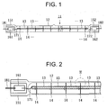
- FIG. 1 is a configuration view showing an entire configuration of a halogen lamp
- FIG. 2 is an enlarged view of a substantial part of FIG. 1
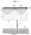
- FIG. 3 is an enlarged view of a substantial part of FIG. 2 with further enlargement.
- a reference numeral 11 denotes a halogen lamp, and it is a tubular halogen lamp which is in heavy use as, for example, a heater for keeping heats in foods and so on.
- the halogen lamp 11 has a bulb 12 made of quartz glass and so on, having a radiation transmissive property.
- the bulb 12 accommodates a tungsten filament 13 being an example of a heat source in a concentric state inside thereof.
- a concentric structure of this filament 13 relative to the bulb 12 is held by anchors 14 plurally arranged in an axial direction within the bulb 12.
- a predetermined amount of a halogen gas is sealed in the bulb 12 together with an inert gas such as argon.
- a pair of sealing end portions 151 and 152 in rectangular flattened shapes are formed at both end portions in the axial direction of the bulb 12 by pinch seals crushing in diametrical direction of the bulb 12.
- Molybdenum foils 161 and 162 in rectangular foil states are respectively embedded in the sealing end portions 151 and 152.
- Both ends of the filament 13 in the axial direction are connected to respective inner end portions of the molybdenum foils 161 and 162 via a pair of inner lead lines 171 and 172, and similarly, a pair of outer lead lines 181 and 182 are respectively connected to respective outer end portions thereof.
- the respective outer lead lines 181 and 182 are extending outside from the respective sealing end portions 151 and 152 while keeping an air-tightness.
- a Frost with a depth of approximately over 4 ⁇ m is formed by a Frost process for forming a fine concave and convex by using, for example, a sandblaster (fine-grained sand).
- a low refractive index film 21 whose major constituent is SiO 2 is formed on a Frost 19
- a high refractive index film 22 whose major constituent is, for example, Fe 2 O 3 being metal oxide is formed on this low refractive index film 21.
- the low refractive index films 21 and the high refractive index films 22 are formed alternately in plural layers.
- FIG. 4 shows an example in which the Frost 19 is formed on an outer surface of a bulb 12, the low refractive index films 21 and the high refractive index films 22 are alternately formed in plural layers, and the films are formed while varying the film thickness in a concave and convex state as shown in FIG. 3.
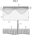
- three kinds of lamps A, B, and C having different Dmin/Dmax produced with varying the depth of the Frost 19, and a lamp produced by alternately forming the low refractive index films 21 and the high refractive index films 22 in plural layers without a Frost are compared.
Landscapes
- Vessels And Coating Films For Discharge Lamps (AREA)
- Resistance Heating (AREA)
Applications Claiming Priority (1)
| Application Number | Priority Date | Filing Date | Title |
|---|---|---|---|
| JP2004287011A JP2006100198A (ja) | 2004-09-30 | 2004-09-30 | 電球形ヒータ、電球形ヒータの製造方法 |
Publications (2)
| Publication Number | Publication Date |
|---|---|
| EP1643540A2 true EP1643540A2 (fr) | 2006-04-05 |
| EP1643540A3 EP1643540A3 (fr) | 2010-01-06 |
Family
ID=35510984
Family Applications (1)
| Application Number | Title | Priority Date | Filing Date |
|---|---|---|---|
| EP05018769A Withdrawn EP1643540A3 (fr) | 2004-09-30 | 2005-08-30 | Elément chauffant à lampe halogène et son procédé de fabrication |
Country Status (2)
| Country | Link |
|---|---|
| EP (1) | EP1643540A3 (fr) |
| JP (1) | JP2006100198A (fr) |
Cited By (1)
| Publication number | Priority date | Publication date | Assignee | Title |
|---|---|---|---|---|
| WO2014036762A1 (fr) * | 2012-09-07 | 2014-03-13 | Lee Wen-Ching | Dispositif de chauffage |
Families Citing this family (1)
| Publication number | Priority date | Publication date | Assignee | Title |
|---|---|---|---|---|
| JP6880874B2 (ja) * | 2017-03-17 | 2021-06-02 | 東芝ライテック株式会社 | ヒータ |
Citations (2)
| Publication number | Priority date | Publication date | Assignee | Title |
|---|---|---|---|---|
| JPH03226959A (ja) | 1990-01-31 | 1991-10-07 | Ushio Inc | 管形白熱電球 |
| JPH0374361B2 (fr) | 1982-12-06 | 1991-11-26 |
Family Cites Families (5)
| Publication number | Priority date | Publication date | Assignee | Title |
|---|---|---|---|---|
| KR890004640B1 (ko) * | 1984-09-28 | 1989-11-21 | 가부시끼 가이샤 도시바 | 광확산코우팅 및 그 형성방법과 코우팅한 램프 |
| JPH0628151B2 (ja) * | 1988-02-10 | 1994-04-13 | 東芝ライテック株式会社 | ハロゲン電球 |
| JPH0279357A (ja) * | 1988-09-14 | 1990-03-19 | Matsushita Electron Corp | 白熱電球 |
| CA2116950A1 (fr) * | 1993-03-22 | 1994-09-23 | Pamela K. Whitman | Lampe a filtre infrarouge et revetement diffusant |
| JP2005108685A (ja) * | 2003-09-30 | 2005-04-21 | Harison Toshiba Lighting Corp | 管球 |
-
2004
- 2004-09-30 JP JP2004287011A patent/JP2006100198A/ja not_active Withdrawn
-
2005
- 2005-08-30 EP EP05018769A patent/EP1643540A3/fr not_active Withdrawn
Patent Citations (2)
| Publication number | Priority date | Publication date | Assignee | Title |
|---|---|---|---|---|
| JPH0374361B2 (fr) | 1982-12-06 | 1991-11-26 | ||
| JPH03226959A (ja) | 1990-01-31 | 1991-10-07 | Ushio Inc | 管形白熱電球 |
Cited By (1)
| Publication number | Priority date | Publication date | Assignee | Title |
|---|---|---|---|---|
| WO2014036762A1 (fr) * | 2012-09-07 | 2014-03-13 | Lee Wen-Ching | Dispositif de chauffage |
Also Published As
| Publication number | Publication date |
|---|---|
| EP1643540A3 (fr) | 2010-01-06 |
| JP2006100198A (ja) | 2006-04-13 |
Similar Documents
| Publication | Publication Date | Title |
|---|---|---|
| US5646472A (en) | Metal halide lamp | |
| EP0617092B1 (fr) | Article ayant un revêtement diffusant la lumière, préparation et usage | |
| KR890004640B1 (ko) | 광확산코우팅 및 그 형성방법과 코우팅한 램프 | |
| JP4653369B2 (ja) | 電気ランプ | |
| EP1643540A2 (fr) | Elément chauffant à lampe halogène et son procédé de fabrication | |
| KR20070039131A (ko) | 적외선 램프 제조 방법 | |
| US6384535B1 (en) | Lamp with shading film | |
| JPH0320960A (ja) | 白熱電球 | |
| CN100459022C (zh) | 高压气体放电灯 | |
| EP1616206A2 (fr) | Lampe | |
| CN101601120A (zh) | 荧光灯、使用了荧光灯的发光装置和显示装置 | |
| EP1670288A1 (fr) | Tube a extremites spheriques | |
| JP2974193B2 (ja) | 自動車前照灯用メタルハライドランプ | |
| JPH03192649A (ja) | 白熱電球 | |
| JP3928499B2 (ja) | 自動車用高色温度白熱電球 | |
| JP2851660B2 (ja) | 白熱電球 | |
| JPH0945295A (ja) | 白熱電球およびこれを用いた反射形照明装置ならびに車両用前照灯 | |
| JPH07320688A (ja) | メタルハライドランプ | |
| JP2011150970A (ja) | 紫外線遮蔽層、蛍光ランプ、及び紫外線遮蔽層の製造方法 | |
| JP2008185637A (ja) | 光学フィルタ | |
| JP5064128B2 (ja) | 蛍光ランプ | |
| JPH09153342A (ja) | メタルハライドランプ | |
| JP2006286398A (ja) | 電球型ヒータ、灯具装置 | |
| JP3716788B2 (ja) | 白熱電球 | |
| JP2809814B2 (ja) | ハロゲン電球 |
Legal Events
| Date | Code | Title | Description |
|---|---|---|---|
| PUAI | Public reference made under article 153(3) epc to a published international application that has entered the european phase |
Free format text: ORIGINAL CODE: 0009012 |
|
| 17P | Request for examination filed |
Effective date: 20050830 |
|
| AK | Designated contracting states |
Kind code of ref document: A2 Designated state(s): AT BE BG CH CY CZ DE DK EE ES FI FR GB GR HU IE IS IT LI LT LU LV MC NL PL PT RO SE SI SK TR |
|
| AX | Request for extension of the european patent |
Extension state: AL BA HR MK YU |
|
| PUAL | Search report despatched |
Free format text: ORIGINAL CODE: 0009013 |
|
| AK | Designated contracting states |
Kind code of ref document: A3 Designated state(s): AT BE BG CH CY CZ DE DK EE ES FI FR GB GR HU IE IS IT LI LT LU LV MC NL PL PT RO SE SI SK TR |
|
| AX | Request for extension of the european patent |
Extension state: AL BA HR MK YU |
|
| 17Q | First examination report despatched |
Effective date: 20100803 |
|
| AKX | Designation fees paid |
Designated state(s): DE FR GB IT |
|
| STAA | Information on the status of an ep patent application or granted ep patent |
Free format text: STATUS: THE APPLICATION IS DEEMED TO BE WITHDRAWN |
|
| 18D | Application deemed to be withdrawn |
Effective date: 20101214 |