EP1643601B1 - Gehäuse zur Aufnahme elektronischer Baugruppen, insbesondere für einen Lufterhitzer - Google Patents
Gehäuse zur Aufnahme elektronischer Baugruppen, insbesondere für einen Lufterhitzer Download PDFInfo
- Publication number
- EP1643601B1 EP1643601B1 EP04023221A EP04023221A EP1643601B1 EP 1643601 B1 EP1643601 B1 EP 1643601B1 EP 04023221 A EP04023221 A EP 04023221A EP 04023221 A EP04023221 A EP 04023221A EP 1643601 B1 EP1643601 B1 EP 1643601B1
- Authority
- EP
- European Patent Office
- Prior art keywords
- housing
- plug part
- cable
- collar
- plug
- Prior art date
- Legal status (The legal status is an assumption and is not a legal conclusion. Google has not performed a legal analysis and makes no representation as to the accuracy of the status listed.)
- Expired - Lifetime
Links
Images
Classifications
-
- H—ELECTRICITY
- H01—ELECTRIC ELEMENTS
- H01R—ELECTRICALLY-CONDUCTIVE CONNECTIONS; STRUCTURAL ASSOCIATIONS OF A PLURALITY OF MUTUALLY-INSULATED ELECTRICAL CONNECTING ELEMENTS; COUPLING DEVICES; CURRENT COLLECTORS
- H01R13/00—Details of coupling devices of the kinds covered by groups H01R12/70 or H01R24/00 - H01R33/00
- H01R13/46—Bases; Cases
- H01R13/52—Dustproof, splashproof, drip-proof, waterproof, or flameproof cases
- H01R13/5202—Sealing means between parts of housing or between housing part and a wall, e.g. sealing rings
-
- F—MECHANICAL ENGINEERING; LIGHTING; HEATING; WEAPONS; BLASTING
- F24—HEATING; RANGES; VENTILATING
- F24H—FLUID HEATERS, e.g. WATER OR AIR HEATERS, HAVING HEAT-GENERATING MEANS, e.g. HEAT PUMPS, IN GENERAL
- F24H3/00—Air heaters
- F24H3/02—Air heaters with forced circulation
- F24H3/022—Air heaters with forced circulation using electric energy supply
-
- H—ELECTRICITY
- H01—ELECTRIC ELEMENTS
- H01R—ELECTRICALLY-CONDUCTIVE CONNECTIONS; STRUCTURAL ASSOCIATIONS OF A PLURALITY OF MUTUALLY-INSULATED ELECTRICAL CONNECTING ELEMENTS; COUPLING DEVICES; CURRENT COLLECTORS
- H01R13/00—Details of coupling devices of the kinds covered by groups H01R12/70 or H01R24/00 - H01R33/00
- H01R13/46—Bases; Cases
- H01R13/52—Dustproof, splashproof, drip-proof, waterproof, or flameproof cases
- H01R13/5213—Covers
-
- H—ELECTRICITY
- H01—ELECTRIC ELEMENTS
- H01R—ELECTRICALLY-CONDUCTIVE CONNECTIONS; STRUCTURAL ASSOCIATIONS OF A PLURALITY OF MUTUALLY-INSULATED ELECTRICAL CONNECTING ELEMENTS; COUPLING DEVICES; CURRENT COLLECTORS
- H01R24/00—Two-part coupling devices, or either of their cooperating parts, characterised by their overall structure
- H01R24/60—Contacts spaced along planar side wall transverse to longitudinal axis of engagement
- H01R24/62—Sliding engagements with one side only, e.g. modular jack coupling devices
- H01R24/64—Sliding engagements with one side only, e.g. modular jack coupling devices for high frequency, e.g. RJ 45
Definitions
- the invention relates to a housing for receiving electrical components, in particular for an air heater, with an electronic connector having at least one chamber in which at least one electronic control device can be arranged, which is connectable via at least one arranged in the chamber of the housing connector part with a data line wherein the housing has in a housing wall at least one plug-in opening aligned with the contact element of the plug part for a mating plug part located on the data line and insertable into the plug part arranged on the other side of the housing wall.
- the RJ-45 connector is a standard for IEC 606 03-7 and is used worldwide for connectors in communication and data networks.
- Such a connector comprises a plug and a socket.
- the socket is usually arranged in a socket, a rack or a device.
- RJ-45 connectors which meet protection class IP 67. These consist of two corresponding connector parts, which are designed as a socket and plug and equipped with sealing elements.
- the disadvantage here is that always both connector parts must be used together and can not be combined with connector parts of another manufacturer, the cost of such a system are far beyond the cost of the standard connector.
- Connectors of this type have a protective sleeve, which protects the connector against external environmental influences, in particular against dirt and moisture.
- the application of the protective sleeve on the already plugged connector is annoying, since, for example, the protective sleeve must be screwed onto the housing of the connector.
- Such a connector is shown in WO 01/20729 A1.
- DE 101 24 932 C1 discloses a plug connector which has a protective sleeve, which is equipped with detent rockers, which engage in the housing of the mating connector part, when the protective sleeve is pushed over the housing.
- an electrical connector for connecting a arranged within an automatic transmission for motor vehicles electronic module with a supply line provided outside the housing is known.
- the electronics module has a plug that passes through a hole in the housing with clearance.
- the supply line is provided with a mating connector in the form of a socket, wherein grooves and ribs are formed on the plug parts, which act as a bayonet lock.
- a molded seal is introduced, which is deformed when plugging the mating connector and hermetically seals the bore.
- the invention is therefore based on the object to propose a splash-proof connection housing, in particular for an air heater, for receiving electrical components and an electrical connector that receives a non-splashproof, connected to a cable connector and protects the connector and the electrical components from environmental influences ,
- connection housing with the features of claim 1. Further advantageous embodiments can be found in the dependent claims.
- the insertion opening is arranged in alignment with the contact elements of the plug part in a housing wall and has a cylindrical collar which receives a rubber-elastic cable feedthrough.
- the rubber-elastic cable feedthrough is larger in diameter than the insertion opening. As a result, it is by a corresponding pressing surface pressure on the cable side Pressed end of the mating connector due to the collar wall, thus sealing this and the insertion.
- the housing has a splash-proof chamber in the housing interior, which receives the electronic control devices and the connector and protects against environmental influences.
- the electronic circuits of the control devices are arranged on a printed circuit board which has a plug portion for connection to the data line.
- connection cable with an attached not splash-proof with the cable molded mating connector part is guided through an insertion into the splash-proof chamber of the connection housing and connected to the plug part of the circuit board.
- the connecting cable and the mating connector part fixed thereto are aligned by a connector part of the printed circuit board Passed breakthrough in the cable gland, wherein the mating connector part is at least partially received by the cable gland.
- the cable bushing has on the side facing the plug part a recess for a locking element of the mating plug part, so that it is not unlocked by the cable gland. After removal of the cable gland, the mating plug part can be unlocked from the outside through the insertion opening.
- the cable bushing may have additional bulges, ribs or the like on the circumference and thickenings on the inner end, which prevent expression of the cable feedthrough due to overpressure in the housing.
- a gap is formed between the collar of the connection housing and the mating plug part, which accommodates the cable feedthrough, wherein the cable feedthrough closes the gap.
- the contact surfaces of the cable gland and the corresponding contact surfaces of the walls of the collar and the mating connector part are designed as sealing surfaces.
- the sealing surfaces of the housing and the mating connector part are arranged coaxially with each other and overlapping. All sealing surfaces are smooth-walled.
- the rubber-elastic grommet with its also coaxial sealing surfaces is positively and under pressure on the inner wall of the housing collar and on the mating connector part and thereby seals the chamber of the connection housing against splashing.
- the cable bushing on the opposite side of the connector on a circumferential ridge, which is aligned with the end face of the cable bushing and rests against the front side of the collar.
- This web seals the gap in addition, since the contact surface is offset at the collar by 90 ° to the coaxial sealing surfaces and thus forms a labyrinth for impinging spray water.
- he offers one Attack surface to remove the grommet if the connector may need loosening to disconnect the device from the data line.
- joining aids are attached to the end faces of the collar and to the end face of the cable leadthrough facing the plug part. These are designed as circumferential chamfers on the end faces and facilitate the insertion of the cable guide when the connector is made.
- the cable bushing according to the invention is designed as a one-piece, homogeneous rubber-elastic molded part. It can thus be produced inexpensively from rubber or from a rubber-like material as an injection molded part. It is therefore easily possible to produce a variant without a passage opening which can be used as a blanking plug for sealing unused insertion openings.
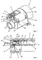
- connection housing 1 for accommodating electrical assemblies 3 is designed in several parts and consists of a housing body 15 and a cover 16, which is screwed tightly to the housing body 15 by means of screws 17. This is a connection housing 1 of an air heater 1 'shown in FIGS. 3 and 4.
- an insertion opening 6 with a cable feedthrough 9 and an opening 21 for a cable 10 with a plug At the housing wall 5 provided for the connections there is an insertion opening 6 with a cable feedthrough 9 and an opening 21 for a cable 10 with a plug.
- the dummy plug 20, which closes a further insertion opening 19, is produced as a variant of the cable feedthrough 9 without opening 21 and seals off unused insertion openings on the housing 1.
- Openings 22 for the electrical power connection and including an opening 23 for the supplied from an external fan and to be heated air.
- a connection collar 24 for the heating element 25 ( Figure 3) and a cap 26 ( Figures 3 and 4) is provided on the opposite side of the terminal housing 1.
- a sealed chamber 2 for receiving the electrical components 3, in particular a control / regulating device arranged.
- the electronic assemblies 3 have a printed circuit board 18 which carries electronic components and a plug part 4 and is fixed in the chamber 2.
- the insertion opening 6 in the side wall 5 is aligned with the plug part 4.
- the plug part 4 is connected via an inserted mating connector part 7 which is electrically connected to a cable 10 to a data line.
- the plug part 4 and the mating connector part 7 are RJ-45 connectors and are cuboidal. This is the usual cheap with the cable 10 potted RJ-45 connector without any special, especially waterproof, training.
- a circumferential collar 8 is formed around the insertion openings 6 and 19 each.
- the collar 8 of the insertion opening 6 receives the mating connector part 7 completely, wherein a gap 11 remains between the collar 8 and the mating connector part 7.
- the gap 7 is filled by a cable bushing 9, which is designed as a rubber-elastic molded part and is pressed by the wall of the collar 8 on the mating connector part 7.
- the grommet 9 is annular and has an aligned with the mating connector part 7 opening 21, through which the mating connector part 7 and the connecting cable 10 are guided.
- On the mating connector part 7 side facing the cable bushing 9 has a recess 27 in which the lever 28 for unlocking the Mating plug 7 ends.
- the grommet 9, the collar 8 and the mating connector part 7 have corresponding sealing surfaces 12, 12 ', which are preferably made smooth-walled.
- the sealing surfaces 12, 12 'of the grommet 9 are positively pressed against the corresponding contact surfaces and thus seal the chamber 2 of the connection housing 1 and the recorded connectors 4, 7 against splashing off.
- the wall of the grommet 9 is made slightly thicker than the gap 11 to be filled is wide, whereby the gap 11 is completely filled.
- the cable bushing 9 has at its plug connection 4, 7 opposite side a circumferential web 14 which is aligned with the end face of the cable bushing 9 and rests against the end face of the collar 8.
- the circumferential web 14 additionally seals against the end face of the collar 8, wherein a labyrinth-like seal to the chamber 2 is generated.
- the cable bushing 9 has a recess 27 for the actuating lever 28 of the RJ-45 connector 7.
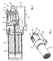
- FIG. 3 shows an overall sectional illustration of the air heater 1 'with the heating element 25 and a cover cap 26 on the connection collar 24, and
- FIG. 4 shows the overall perspective view.
- This embodiment of the connection housing 1 of the air heater 1 ' is a cost-effective protection against splash water and dust guaranteed.
Landscapes
- Connector Housings Or Holding Contact Members (AREA)
- Insertion, Bundling And Securing Of Wires For Electric Apparatuses (AREA)
- Devices For Blowing Cold Air, Devices For Blowing Warm Air, And Means For Preventing Water Condensation In Air Conditioning Units (AREA)
- Direct Air Heating By Heater Or Combustion Gas (AREA)
Description
- Die Erfindung betrifft ein Gehäuse zur Aufnahme von elektrischen Baugruppen, insbesondere für einen Lufterhitzer, mit einem elektronischen Steckverbinder mit mindestens einer Kammer, in der mindestens eine elektronische Steuereinrichtung anordenbar ist, die über mindestens ein in der Kammer des Gehäuses angeordnetes Steckerteil mit einer Datenleitung verbindbar ist, wobei das Gehäuse in einer Gehäusewand mindestens eine mit dem Kontaktelement des Steckerteils fluchtende Einstecköffnung für ein an der Datenleitung befindliches Gegensteckerteil aufweist, das in das auf der anderen Seite der Gehäusewand angeordnete Steckerteil einsteckbar ist.
- Es sind eine Vielzahl von modular ausgestalteten Steckverbindungssystemen bekannt, um beispielsweise Telefonleitungen, Computersysteme oder Netzwerke miteinander oder mit Geräten zu verbinden. So ist beispielsweise die RJ-45-Steckverbindung ein nach der IEC 606 03-7 genormter und weltweit angewandter Standard für Steckverbinder in Kommunikations- und Datennetzen. Eine derartige Steckverbindung umfasst einen Stecker sowie eine Steckbuchse. Die Steckbuchse ist üblicherweise in einer Steckdose, einem Rack oder einem Gerät angeordnet.
- Modern ausgerüstete Gebäude weisen heutzutage eine sogenannte universelle Gebäudeverkabelung mit einer Vielzahl von Steckbuchsen auf, um je nach Bedarf Telefone, Telefaxgeräte, Computer, Drucker und Modems miteinander oder mit anderen Geräten zu verbinden. Nachteilig an diesen bekannten Steckverbindungen ist die Tatsache, dass sie für industrielle Anwendungen kaum geeignet sind, da eine sichere Netzwerkfunktion zur Steuerung von elektrischen Geräten, beispielsweise einen Lufterhitzer mittels eines Bussystems, unter harten Umweltbedingungen, wie diese heute in der Industrie auftreten, nicht gewährleistet ist. So können bekannte Steckverbindungen basierend auf dem RJ-45-Steckverbindungssystem eine Schutzklasse wie die IP 67 gemäß Norm IEC 60529 häufig nicht erfüllen, was bedeutet, dass die an sich sehr weit verbreitete und kostengünstige RJ-45-Steckverbindung im industriellen Umfeld mit erhöhten Anforderungen nicht geeignet ist, weil Außeneinwirkungen wie Vibrationen oder Schock bzw. Beeinträchtigungen durch Feuchtigkeit, Schmutz oder Staub auftreten können.
- Für kritische Anwendungsfälle sind speziell ausgeführte RJ-45-Steckverbindungen bekannt, welche die Schutzklasse IP 67 erfüllen. Diese bestehen aus jeweils zwei korrespondierenden Steckverbinderteilen, die als Buchse und Stecker ausgeführt und mit Dichtelementen ausgestattet sind. Nachteilig ist dabei, dass immer beide Steckverbinderteile gemeinsam eingesetzt werden müssen und sich nicht mit Steckverbinderteilen eines anderen Herstellers kombinieren lassen, wobei die Kosten eines solchen Systems weit über den Kosten des Standardsteckverbinders liegen.
- Steckverbinder dieser Gattung weisen eine Schutzhülse auf, die die Steckverbindung gegen äußere Umwelteinflüsse, insbesondere gegen Schmutz und Feuchtigkeit, schützt. Bei den bekannten Steckverbindern ist das Aufbringen der Schutzhülse über die bereits gesteckte Steckverbindung lästig, da beispielsweise die Schutzhülse auf das Gehäuse des Steckverbinders aufgeschraubt werden muss. Einen solchen Steckverbinder zeigt die WO 01/20729 A1. In der DE 101 24 932 C1 wird ein Steckverbinder offenbart, der eine Schutzhülse aufweist, die mit Rastwippen ausgestattet ist, welche in das Gehäuse des Gegenverbinderteils einrasten, wenn die Schutzhülse über das Gehäuse geschoben wird.
- Aus der US 6,290,537 B1 ist eine elektrische Steckverbindung zum Verbinden eines innerhalb eines Automatikgetriebes für Kraftfahrzeuge angeordneten Elektronikmoduls mit einer außerhalb des Gehäuses vorgesehenen Zuleitung bekannt. Das Elektronikmodul weist einen Stecker auf, der mit Spiel eine Bohrung im Gehäuse durchsetzt. Die Zuleitung ist mit einem Gegenstecker in Form einer Buchse versehen, wobei an den Steckerteilen Nuten und Rippen ausgebildet sind, die als Bajonettverriegelung wirken. Im Raum zwischen dem Stecker und der Gehäusebohrung ist eine Formdichtung eingebracht, die beim Aufstecken des Gegensteckers verformt wird und die Bohrung hermetisch abdichtet.
- Der Erfindung liegt daher die Aufgabe zu Grunde, ein spritzwassergeschütztes Anschlussgehäuse, insbesondere für einen Lufterhitzer, zur Aufnahme von elektrischen Baugruppen und einer elektrischen Steckverbindung vorzuschlagen, die einen nicht spritzwassergeschützten, mit einem Anschlusskabel verbundenen Steckverbinder aufnimmt und die Steckverbindung und die elektrischen Baugruppen vor Umwelteinflüssen schützt.
- Diese Aufgabe wird erfindungsgemäß durch ein Anschlussgehäuse mit den Merkmalen des Anspruchs 1 gelöst. Weitere vorteilhafte Ausgestaltungen sind den Unteransprüchen zu entnehmen.
- Bei dem erfindungsgemäßen Anschlussgehäuse zur Aufnahme von elektronischen Baugruppen, vorzugsweise elektronischen Steuereinrichtungen, ist die Einstecköffnung fluchtend zu den Kontaktelementen des Steckerteils in einer Gehäusewand angeordnet und weist einen zylindrischen Kragen auf, der eine gummielastische Kabeldurchführung aufnimmt. Die gummielastische Kabeldurchführung ist im Durchmesser größer als die Einstecköffnung. Dadurch wird es durch einen entsprechenden Pressflächendruck auf das kabelseitige Ende des Gegensteckers aufgrund der Kragenwand gepresst und dichtet damit diesen und die Einstecköffnung ab. Das Gehäuse weist eine spritzwassergeschützte Kammer im Gehäuseinnern auf, welche die elektronischen Steuereinrichtungen und die Steckverbindung aufnimmt und gegen Umwelteinflüsse schützt. Die elektronischen Schaltungen der Steuereinrichtungen sind auf einer Leiterplatte angeordnet, die einen Steckeranteil zum Anschluss an die Datenleitung aufweist. Das Anschlusskabel mit einem daran befestigten nicht spritzwassergeschützten mit dem Kabel vergossenen Gegensteckerteil ist durch eine Einstecköffnung in die spritzwasserdichte Kammer des Anschlussgehäuses geführt und mit dem Steckerteil der Leiterplatte verbunden. Das Anschlusskabel und das daran fixierte Gegensteckerteil sind durch einen mit dem Steckerteil der Leiterplatte fluchtenden Durchbruch in der Kabeldurchführung geführt, wobei das Gegensteckerteil zumindest teilweise von der Kabeldurchführung aufgenommen ist.
- Die Kabeldurchführung weist auf der dem Steckerteil zugewandten Seite eine Ausnehmung für ein Verriegelungselement des Gegensteckerteils auf, damit dies nicht durch die Kabeldurchführung entriegelt wird. Nach der Entnahme der Kabeldurchführung kann das Gegensteckerteil von außen durch die Einstecköffnung hindurch entriegelt werden. Zusätzlich kann die Kabeldurchführung noch am Umfang zusätzliche Wülste, Rippen oder ähnliches sowie am inneren Ende Verdickungen aufweisen, die ein Ausdrücken der Kabeldurchführung aufgrund eines Überdruckes in dem Gehäuse verhindern.
- Durch das Einstecken des Gegensteckerteils in das Steckerteil der Steuerschaltung wird zwischen dem Kragen des Anschlussgehäuses und dem Gegensteckerteil ein Spalt ausgebildet, welcher die Kabeldurchführung aufnimmt, wobei die Kabeldurchführung den Spalt verschließt.
- Zweckmäßigerweise sind die Anlageflächen der Kabeldurchführung und die korrespondierenden Anlageflächen der Wände des Kragens und des Gegensteckerteils als Dichtflächen ausgeführt. Erfindungsgemäß sind die Dichtflächen des Gehäuses und des Gegensteckerteils koaxial zueinander und überlappend angeordnet. Alle Dichtflächen sind glattwandig ausgeführt. Die gummielastische Kabeldurchführung liegt mit ihren ebenfalls koaxial angeordneten Dichtflächen formschlüssig und unter Druck an der Innenwand des Gehäusekragens und am Gegensteckerteil an und dichtet die Kammer des Anschlussgehäuses dadurch gegen Spritzwasser ab.
- In einer weiteren vorteilhaften Ausgestaltung weist die Kabeldurchführung an der der Steckverbindung gegenüberliegenden Seite einen umlaufenden Steg auf, der mit der Stirnfläche der Kabeldurchführung fluchtet und an der Stirnseite des Kragens anliegt. Dieser Steg dichtet den Spalt zusätzlich ab, da dessen Anlagefläche am Kragen um 90° zu den koaxial angeordneten Dichtflächen versetzt ist und somit ein Labyrinth für auftreffendes Spritzwasser bildet. Zusätzlich bietet er eine Angriffsfläche zum Entfernen der Kabeldurchführung, falls die Steckverbindung eventuell gelöst werden muss, um das Gerät von der Datenleitung zu trennen.
- Vorteilhafterweise sind an den Stirnflächen des Kragens und an der zum Steckerteil weisenden Stirnfläche der Kabeldurchführung Fügehilfen angebracht. Diese sind als umlaufende Fasen an den Stirnflächen ausgebildet und erleichtern das Einstecken der Kabelführung, wenn die Steckverbindung hergestellt ist.
- Die erfindungsgemäße Kabeldurchführung ist als ein einstückiges, homogenes gummielastisches Formteil ausgebildet. Es kann somit kostengünstig aus Gummi oder aus einem gummiähnlichen Material als Spritzgießteil produziert werden. Es ist daher leicht möglich, eine Variante ohne Durchführungsöffnung herzustellen, die als Blindstopfen zum Abdichten unbenutzter Einstecköffnungen verwendbar ist.
- Nachfolgend wird die Erfindung anhand eines in der Zeichnung dargestellten Ausführungsbeispiels näher erläutert. Es zeigen:
- Figur 1
- eine perspektivische Ansicht eines erfindungsgemäßen Anschlussgehäuses;
- Figur 2
- eine Schnittdarstellung des Anschlussbereichs des Anschlussgehäuses gemäß Figur 1;
- Figur 3
- einen Längsschnitt durch einen Lufterhitzer; und
- Figur 4
- eine perspektivische Ansicht eines Lufterhitzers.
- Das in der Figur1 dargestellte, erfindungsgemäße Anschlussgehäuse 1 zur Aufnahme von elektrischen Baugruppen 3 ist mehrstückig ausgeführt und besteht aus einem Gehäusekörper 15 und einem Deckel 16, der dicht mit dem Gehäusekörper 15 mittels Schrauben 17 verschraubt ist. Es handelt sich hierbei um ein Anschlussgehäuse 1 eines in den Figuren 3 und 4 dargestellten Lufterhitzers 1'.
- An der für die Anschlüsse vorgesehenen Gehäusewand 5 befindet sich eine Einstecköffnung 6 mit einer Kabeldurchführung 9 und einer Öffnung 21 für ein Kabel 10 mit einem Stecker. Der Blindstopfen 20, der eine weitere Einstecköffnung 19 verschließt, wird als Variante der Kabeldurchführung 9 ohne Öffnung 21 hergestellt und dichtet unbenutzte Einstecköffnungen am Gehäuse 1 ab. Unterhalb der Einstecköffnungen 6, 19 befinden sich Öffnungen 22 für den elektrischen Leistungsanschluss und darunter eine Öffnung 23 für die von einem externen Gebläse zugeführte und zu erhitzende Luft. Auf der gegenüberliegenden Seite des Anschlussgehäuses 1 ist ein Anschlussbund 24 für das Heizelement 25 (Figur 3) und eine Abdeckkappe 26 (Figuren 3 und 4) vorgesehen.
- Unter dem abnehmbaren Deckel 16 ist gemäß Figur 2 eine dichte Kammer 2 zur Aufnahme der elektrischen Baugruppen 3, insbesondere einer Steuer-/Regeleinrichtung, angeordnet. Die elektronischen Baugruppen 3 weisen eine Leiterplatte 18 auf, die elektronische Bauteile und ein Steckerteil 4 trägt und in der Kammer 2 fixiert ist. Die Einstecköffnung 6 in der Seitenwand 5 fluchtet mit dem Steckerteil 4. Das Steckerteil 4 ist über ein eingestecktes Gegensteckerteil 7, das mit einem Kabel 10 elektrisch leitend verbunden ist, an einer Datenleitung angeschlossen. Das Steckerteil 4 und das Gegensteckerteil 7 sind RJ-45-Steckverbinder und sind quaderförmig ausgeführt. Es handelt sich hier um übliche kostengünstig mit dem Kabel 10 vergossene RJ-45-Steckverbinder ohne sonstige besondere, insbesondere wasserdichte, Ausbildungen. An die Gehäusewand 5 ist um die Einstecköffnungen 6 und 19 je ein umlaufender Kragen 8 angeformt. Der Kragen 8 der Einstecköffnung 6 nimmt das Gegensteckerteil 7 komplett auf, wobei zwischen dem Kragen 8 und dem Gegensteckerteil 7 ein Spalt 11 verbleibt. Der Spalt 7 wird durch eine Kabeldurchführung 9 ausgefüllt, der als gummielastisches Formteil ausgeführt ist und durch die Wand des Kragens 8 auf das Gegensteckerteil 7 gepresst wird. Die Kabeldurchführung 9 ist ringförmig gestaltet und weist eine mit dem Gegensteckerteil 7 fluchtende Öffnung 21 auf, durch die das Gegensteckerteil 7 und das Anschlusskabel 10 geführt sind. Auf der dem Gegensteckerteil 7 zugewandten Seite weist die Kabeldurchführung 9 eine Ausnehmung 27 auf, in der der Hebel 28 zum Entriegeln des Gegensteckteils 7 endet. Die Kabeldurchführung 9, der Kragen 8 und das Gegensteckerteil 7 weisen korrespondierende Dichtflächen 12, 12' auf, die vorzugsweise glattwandig ausgeführt sind. Dies ermöglicht ein nachträgliches Verschlie-ßen des Spaltes 11 durch Eindrücken der Kabeldurchführung 9 in die Einstecköffnung 6, nachdem das Gegensteckerteil 7 in das Steckerteil 4 eingesteckt ist,. Die Dichtflächen 12, 12' der Kabeldurchführung 9 sind formschlüssig an die korrespondierenden Anlageflächen angepresst und dichten somit die Kammer 2 des Anschlussgehäuses 1 und die aufgenommenen Steckverbindungen 4, 7 gegen Spritzwasser ab. Zweckmäßigerweise ist die Wandung der Kabeldurchführung 9 etwas dicker ausgeführt als der auszufüllende Spalt 11 breit ist, wodurch der Spalt 11 komplett ausgefüllt wird. Die Kabeldurchführung 9 weist an ihrem der Steckverbindung 4, 7 gegenüberliegenden Seite einen umlaufenden Steg 14 auf, der mit der Stirnfläche der Kabeldurchführung 9 fluchtet und an der Stirnfläche des Kragens 8 anliegt. Der umlaufende Steg 14 dichtet zusätzlich gegen die Stirnfläche des Kragens 8 ab, wobei eine labyrinthartige Abdichtung zur Kammer 2 erzeugt wird. Um das Eindrücken der Kabeldurchführung 9 zu erleichtern, sind an den Stirnflächen der Kabeldurchführung 9 und des Kragens 8 Fügehilfen 13, 13' angeordnet, die als umlaufende Fasen angeformt sind. An der der Steckverbindung 4, 7 zugewandten Seite weist die Kabeldurchführung 9 eine Ausnehmung 27 für den Betätigungshebel 28 des RJ-45-Steckers 7 auf.
- Figur 3 zeigt in einer Gesamtschnittdarstellung den Lufterhitzer 1' mit dem Heizelement 25 und einer Abdeckkappe 26 an dem Anschlussbund 24 und die Figur 4 die perspektivische Gesamtansicht. Durch diese Ausgestaltung des Anschlussgehäuses 1 des Lufterhitzers 1' ist ein kostengünstiger Schutz vor Spritzwasser und auch Staub gewährleistet.
Claims (7)
- Gehäuse (1) zur Aufnahme von elektrischen Baugruppen (3), insbesondere Lufterhitzer (1'), mit mindestens einer Kammer (2), in der mindestens eine elektronische Steuereinrichtung (3) anordenbar ist, die über mindestens ein in der Kammer (2) des Gehäuses (1) angeordnetes Steckerteil (4) mit einem Datenleitungskabel (10) verbindbar ist, wobei das Gehäuse (1) in einer Gehäusewand (5) mindestens eine mit dem Kontaktelement des Steckerteils (4) fluchtende Einstecköffnung (6) für ein an der Datenleitung (10) befindliches Gegensteckerteil (7) aufweist, das in das auf der anderen Seite der Gehäusewand (5) angeordnete Steckerteil (4) einsteckbar ist, dadurch gekennzeichnet, dass außen an der Gehäusewand (5) ein Kragen (8) angeformt ist, in den eine elastische Kabeldurchführung (9), nachdem das Steckerteil (4) mit dem Gegensteckerteil (7) verbunden ist, einsteckbar ist, die das Gegensteckerteil (7) und einen Endabschnitt des Kabels (10) zumindest teilweise übergreifend aufnimmt, wobei die Kabeldurchführung (9) die in der Kammer (2) des Gehäuses (1) angeordneten Steckerteile (4, 7) sowie die elektrischen Baugruppen (3) vor Umwelteinflüssen, insbesondere Feuchtigkeit schützt.
- Gehäuse nach einem der vorgenannten Ansprüche, dadurch gekennzeichnet, dass die Kabeldurchführung (9) auf der dem Steckerteil (4) zugewandten Seite eine Ausnehmung (27) für ein Verriegelungselement (28) des Gegensteckerteils (7) aufweist.
- Gehäuse nach einem der vorgenannten Ansprüche, dadurch gekennzeichnet, dass die Kabeldurchführung (9) im Außendurchmesser größer ist als Innendurchmesser des Kragens (8).
- Gehäuse nach einem der vorgenannten Ansprüche, dadurch gekennzeichnet, dass die Kabeldurchführung (9) Dichtflächen (12) aufweist, die an Wänden des Kragens (8) sowie des Gegensteckerteils (7) angepresst sind.
- Gehäuse nach einem der vorgenannten Ansprüche, dadurch gekennzeichnet, dass die Kabeldurchführung (9) an ihrem äußeren Ende einen umlaufenden Steg (14) aufweist, der an der Stirnseite des Kragens (8) anliegt.
- Gehäuse nach einem der vorgenannten Ansprüche, dadurch gekennzeichnet, dass die Kabeldurchführung (9) als ein einstückiges homogenes Formteil ausgebildet ist.
- Gehäuse nach einem der vorgenannten Ansprüche, dadurch gekennzeichnet, dass das Steckerteil (4) und das Gegensteckerteil (7) RJ-45-Steckverbinder sind.
Priority Applications (3)
| Application Number | Priority Date | Filing Date | Title |
|---|---|---|---|
| EP04023221A EP1643601B1 (de) | 2004-09-29 | 2004-09-29 | Gehäuse zur Aufnahme elektronischer Baugruppen, insbesondere für einen Lufterhitzer |
| AT04023221T ATE331321T1 (de) | 2004-09-29 | 2004-09-29 | Gehäuse zur aufnahme elektronischer baugruppen, insbesondere für einen lufterhitzer |
| DE502004000851T DE502004000851D1 (de) | 2004-09-29 | 2004-09-29 | Gehäuse zur Aufnahme elektronischer Baugruppen, insbesondere für einen Lufterhitzer |
Applications Claiming Priority (1)
| Application Number | Priority Date | Filing Date | Title |
|---|---|---|---|
| EP04023221A EP1643601B1 (de) | 2004-09-29 | 2004-09-29 | Gehäuse zur Aufnahme elektronischer Baugruppen, insbesondere für einen Lufterhitzer |
Publications (2)
| Publication Number | Publication Date |
|---|---|
| EP1643601A1 EP1643601A1 (de) | 2006-04-05 |
| EP1643601B1 true EP1643601B1 (de) | 2006-06-21 |
Family
ID=34926781
Family Applications (1)
| Application Number | Title | Priority Date | Filing Date |
|---|---|---|---|
| EP04023221A Expired - Lifetime EP1643601B1 (de) | 2004-09-29 | 2004-09-29 | Gehäuse zur Aufnahme elektronischer Baugruppen, insbesondere für einen Lufterhitzer |
Country Status (3)
| Country | Link |
|---|---|
| EP (1) | EP1643601B1 (de) |
| AT (1) | ATE331321T1 (de) |
| DE (1) | DE502004000851D1 (de) |
Families Citing this family (1)
| Publication number | Priority date | Publication date | Assignee | Title |
|---|---|---|---|---|
| CN113097796B (zh) * | 2021-04-29 | 2024-06-21 | 克拉玛依市尚正石油科技有限公司 | 一种井下电缆湿对接装置 |
Family Cites Families (4)
| Publication number | Priority date | Publication date | Assignee | Title |
|---|---|---|---|---|
| US4520256A (en) * | 1983-05-16 | 1985-05-28 | Conair Corporation | Hot air curler having a remote air inlet and a slide switch and actuating arm within its handle |
| US4822293A (en) * | 1987-11-20 | 1989-04-18 | General Dynamics, Pomona Division | Bell housing sealing assembly for mounted connector |
| DE19848725B4 (de) * | 1998-10-22 | 2006-08-31 | Zf Friedrichshafen Ag | Elektrische Steckverbindung |
| DE10124932C1 (de) * | 2001-05-21 | 2002-10-10 | Ria Btr Prod Gmbh | Elektrischer Steckverbinder |
-
2004
- 2004-09-29 DE DE502004000851T patent/DE502004000851D1/de not_active Expired - Lifetime
- 2004-09-29 EP EP04023221A patent/EP1643601B1/de not_active Expired - Lifetime
- 2004-09-29 AT AT04023221T patent/ATE331321T1/de not_active IP Right Cessation
Also Published As
| Publication number | Publication date |
|---|---|
| ATE331321T1 (de) | 2006-07-15 |
| EP1643601A1 (de) | 2006-04-05 |
| DE502004000851D1 (de) | 2006-08-03 |
Similar Documents
| Publication | Publication Date | Title |
|---|---|---|
| EP2332221B1 (de) | Steckverbinderbuchse für die Daten- und Kommunikationstechnik | |
| US6475009B2 (en) | Industrial telecommunications connector | |
| EP1814202B1 (de) | Kupplung | |
| EP0368115A2 (de) | Zentrale Stromverteilungsanordnung, insbesondere für Kraftfahrzeuge | |
| EP1413013A1 (de) | Schutzvorrichtung für eine steckverbindung | |
| EP1088374B1 (de) | Durchführungsadapter für schaltschränke | |
| DE102015119002A1 (de) | Elektronikeinheit | |
| EP1746698B1 (de) | Kabeldurchführung mit Membranventil | |
| WO2007082647A2 (de) | Anschlussadapter für sensoren oder aktuatoren | |
| EP3869622A1 (de) | Ladebuchse für ein elektrofahrzeug | |
| EP4135168A1 (de) | Elektrische schnittstelleneinrichtung für einen elektromotor | |
| DE102012102842B4 (de) | Befestigung und Abdichtung von Steckanschlussmodulen in einer Gehäusewand | |
| DE19816216C2 (de) | Elektrischer Stecker und Steckverbindung | |
| DE102019128575A1 (de) | Kraftrad mit USB-Ladeanschluss | |
| EP1643601A1 (de) | Gehäuse zur Aufnahme elektronischer Baugruppen, insbesondere für einen Lufterhitzer | |
| DE10110470C2 (de) | Vorrichtung zur Schutzgraderhöhung | |
| DE10162405A1 (de) | Steckverbindung | |
| EP2255603A1 (de) | Verfahren zur aufnahme eines elektrischen/elektronischen bauteils und entsprechendes montageverfahren sowie abdeckung für eine solche vorrichtung | |
| EP2991165B1 (de) | Elektrischer steckverbinder, verbinderelement und verwendung | |
| WO2005122340A1 (de) | Verbindungssystem zur geschützten verbindung von leitungen | |
| EP4139998B1 (de) | Steckverbindersystem | |
| DE102017104294B4 (de) | Anordnung mit einem Leiterplattengehäuse | |
| DE102008058926B4 (de) | Elektromotorische Antriebseinheit für Stellantriebe in Kraftfahrzeug | |
| EP1134850A2 (de) | Durchführungsadapter und Steckverbinder für einen Durchführungsadapter | |
| EP0634086B1 (de) | Steckbare schraubklemmenanordnung für kompakte automatisierungsgeräte |
Legal Events
| Date | Code | Title | Description |
|---|---|---|---|
| GRAP | Despatch of communication of intention to grant a patent |
Free format text: ORIGINAL CODE: EPIDOSNIGR1 |
|
| GRAS | Grant fee paid |
Free format text: ORIGINAL CODE: EPIDOSNIGR3 |
|
| PUAI | Public reference made under article 153(3) epc to a published international application that has entered the european phase |
Free format text: ORIGINAL CODE: 0009012 |
|
| 17P | Request for examination filed |
Effective date: 20050204 |
|
| AK | Designated contracting states |
Kind code of ref document: A1 Designated state(s): AT CH DE FR GB IT LI |
|
| GRAA | (expected) grant |
Free format text: ORIGINAL CODE: 0009210 |
|
| AK | Designated contracting states |
Kind code of ref document: B1 Designated state(s): AT BE CH DE ES FI FR GB IT LI NL SE |
|
| PG25 | Lapsed in a contracting state [announced via postgrant information from national office to epo] |
Ref country code: IT Free format text: LAPSE BECAUSE OF FAILURE TO SUBMIT A TRANSLATION OF THE DESCRIPTION OR TO PAY THE FEE WITHIN THE PRESCRIBED TIME-LIMIT;WARNING: LAPSES OF ITALIAN PATENTS WITH EFFECTIVE DATE BEFORE 2007 MAY HAVE OCCURRED AT ANY TIME BEFORE 2007. THE CORRECT EFFECTIVE DATE MAY BE DIFFERENT FROM THE ONE RECORDED. Effective date: 20060621 Ref country code: LI Free format text: LAPSE BECAUSE OF THE APPLICANT RENOUNCES Effective date: 20060621 Ref country code: FI Free format text: LAPSE BECAUSE OF FAILURE TO SUBMIT A TRANSLATION OF THE DESCRIPTION OR TO PAY THE FEE WITHIN THE PRESCRIBED TIME-LIMIT Effective date: 20060621 Ref country code: CH Free format text: LAPSE BECAUSE OF THE APPLICANT RENOUNCES Effective date: 20060621 Ref country code: NL Free format text: LAPSE BECAUSE OF FAILURE TO SUBMIT A TRANSLATION OF THE DESCRIPTION OR TO PAY THE FEE WITHIN THE PRESCRIBED TIME-LIMIT Effective date: 20060621 Ref country code: GB Free format text: LAPSE BECAUSE OF FAILURE TO SUBMIT A TRANSLATION OF THE DESCRIPTION OR TO PAY THE FEE WITHIN THE PRESCRIBED TIME-LIMIT Effective date: 20060621 |
|
| REG | Reference to a national code |
Ref country code: GB Ref legal event code: FG4D Free format text: NOT ENGLISH |
|
| REG | Reference to a national code |
Ref country code: CH Ref legal event code: EP |
|
| PG25 | Lapsed in a contracting state [announced via postgrant information from national office to epo] |
Ref country code: DE Free format text: LAPSE BECAUSE OF THE APPLICANT RENOUNCES Effective date: 20060726 |
|
| REF | Corresponds to: |
Ref document number: 502004000851 Country of ref document: DE Date of ref document: 20060803 Kind code of ref document: P |
|
| REG | Reference to a national code |
Ref country code: SE Ref legal event code: TRGR |
|
| REG | Reference to a national code |
Ref country code: CH Ref legal event code: PL |
|
| PG25 | Lapsed in a contracting state [announced via postgrant information from national office to epo] |
Ref country code: BE Free format text: LAPSE BECAUSE OF NON-PAYMENT OF DUE FEES Effective date: 20060930 |
|
| NLV1 | Nl: lapsed or annulled due to failure to fulfill the requirements of art. 29p and 29m of the patents act | ||
| AKX | Designation fees paid |
Designated state(s): AT BE CH DE ES FI FR GB IT LI NL SE |
|
| GBV | Gb: ep patent (uk) treated as always having been void in accordance with gb section 77(7)/1977 [no translation filed] |
Effective date: 20060621 |
|
| PLBE | No opposition filed within time limit |
Free format text: ORIGINAL CODE: 0009261 |
|
| STAA | Information on the status of an ep patent application or granted ep patent |
Free format text: STATUS: NO OPPOSITION FILED WITHIN TIME LIMIT |
|
| EN | Fr: translation not filed | ||
| 26N | No opposition filed |
Effective date: 20070322 |
|
| PG25 | Lapsed in a contracting state [announced via postgrant information from national office to epo] |
Ref country code: AT Free format text: LAPSE BECAUSE OF NON-PAYMENT OF DUE FEES Effective date: 20060929 |
|
| BERE | Be: lapsed |
Owner name: LEISTER PROCESS TECHNOLOGIES Effective date: 20060930 |
|
| PG25 | Lapsed in a contracting state [announced via postgrant information from national office to epo] |
Ref country code: SE Free format text: LAPSE BECAUSE OF NON-PAYMENT OF DUE FEES Effective date: 20070930 Ref country code: FR Free format text: LAPSE BECAUSE OF FAILURE TO SUBMIT A TRANSLATION OF THE DESCRIPTION OR TO PAY THE FEE WITHIN THE PRESCRIBED TIME-LIMIT Effective date: 20070504 |
|
| EUG | Se: european patent has lapsed | ||
| PGFP | Annual fee paid to national office [announced via postgrant information from national office to epo] |
Ref country code: SE Payment date: 20060725 Year of fee payment: 3 |
|
| PG25 | Lapsed in a contracting state [announced via postgrant information from national office to epo] |
Ref country code: FR Free format text: LAPSE BECAUSE OF FAILURE TO SUBMIT A TRANSLATION OF THE DESCRIPTION OR TO PAY THE FEE WITHIN THE PRESCRIBED TIME-LIMIT Effective date: 20060621 |
|
| PG25 | Lapsed in a contracting state [announced via postgrant information from national office to epo] |
Ref country code: ES Free format text: LAPSE BECAUSE OF NON-PAYMENT OF DUE FEES Effective date: 20060930 |