EP1643617A2 - Corps de rotor et correspondant procédé de production pour une machine électrique - Google Patents
Corps de rotor et correspondant procédé de production pour une machine électrique Download PDFInfo
- Publication number
- EP1643617A2 EP1643617A2 EP05013672A EP05013672A EP1643617A2 EP 1643617 A2 EP1643617 A2 EP 1643617A2 EP 05013672 A EP05013672 A EP 05013672A EP 05013672 A EP05013672 A EP 05013672A EP 1643617 A2 EP1643617 A2 EP 1643617A2
- Authority
- EP
- European Patent Office
- Prior art keywords
- rotor
- shaft
- projections
- band
- rotor body
- Prior art date
- Legal status (The legal status is an assumption and is not a legal conclusion. Google has not performed a legal analysis and makes no representation as to the accuracy of the status listed.)
- Withdrawn
Links
Images




Classifications
-
- H—ELECTRICITY
- H02—GENERATION; CONVERSION OR DISTRIBUTION OF ELECTRIC POWER
- H02K—DYNAMO-ELECTRIC MACHINES
- H02K1/00—Details of the magnetic circuit
- H02K1/06—Details of the magnetic circuit characterised by the shape, form or construction
- H02K1/22—Rotating parts of the magnetic circuit
- H02K1/27—Rotor cores with permanent magnets
- H02K1/2706—Inner rotors
- H02K1/272—Inner rotors the magnetisation axis of the magnets being perpendicular to the rotor axis
- H02K1/274—Inner rotors the magnetisation axis of the magnets being perpendicular to the rotor axis the rotor consisting of two or more circumferentially positioned magnets
- H02K1/2753—Inner rotors the magnetisation axis of the magnets being perpendicular to the rotor axis the rotor consisting of two or more circumferentially positioned magnets the rotor consisting of magnets or groups of magnets arranged with alternating polarity
- H02K1/276—Magnets embedded in the magnetic core, e.g. interior permanent magnets [IPM]
- H02K1/2766—Magnets embedded in the magnetic core, e.g. interior permanent magnets [IPM] having a flux concentration effect
- H02K1/2773—Magnets embedded in the magnetic core, e.g. interior permanent magnets [IPM] having a flux concentration effect consisting of tangentially magnetized radial magnets
-
- H—ELECTRICITY
- H02—GENERATION; CONVERSION OR DISTRIBUTION OF ELECTRIC POWER
- H02K—DYNAMO-ELECTRIC MACHINES
- H02K15/00—Processes or apparatus specially adapted for manufacturing, assembling, maintaining or repairing of dynamo-electric machines
- H02K15/02—Processes or apparatus specially adapted for manufacturing, assembling, maintaining or repairing of dynamo-electric machines of stator or rotor bodies
- H02K15/03—Processes or apparatus specially adapted for manufacturing, assembling, maintaining or repairing of dynamo-electric machines of stator or rotor bodies having permanent magnets
Definitions
- the invention relates to a rotor body for a rotor of an electrical machine and to a method for producing a rotor body.
- the rotor body according to the invention can be used in many types of electrical machines, such as DC motors and generators.
- a preferred field of application of the invention are brushless DC motors and other permanent magnet motors.
- motors it is generally known to provide permanent magnets on the circumference of a rotor yoke or embed in this.
- the invention is further applicable to electric motors or generators which may be configured as an internal rotor motor or external rotor motor.
- Electric motors with an internal rotor configuration have a rotor return, which is applied to a shaft, and one or more permanent magnets, which are applied to the rotor yoke or embedded in these.
- the motors include a stator assembly of e.g. a number of packetized metal sheets forming an annular stator yoke from which pole pieces protrude inwardly. On the pole pieces phase windings are applied.
- the rotor assembly is coaxially inserted into the stator assembly. In an external rotor configuration, the rotor assembly coaxially surrounds the stator.
- the invention is particularly applicable to an internal rotor motor having a rotor assembly with embedded permanent magnets.
- Fig. 8 shows basically the structure of an electric motor with a housing 100 in which a stator assembly 112, a rotor assembly 114 and bearings 116, 118 are accommodated for rotatably supporting the rotor assembly.
- the stator assembly 112 includes packetized metal sheets 120 and windings 122 and defines an interior space into which the rotor assembly 114 is inserted.
- the rotor assembly 114 includes the motor shaft 126, an iron yoke 128 and permanent magnets 130.
- the bearings 116, 118 for supporting the rotor assembly may be integrated into a flange 132 of the motor housing 100.
- Fig. 8 serves to explain the basic structure of an electric motor. As stated at the outset, In the preferred embodiment, the invention relates to a rotor yoke for such an electric motor, wherein the permanent magnets are embedded in the rotor yoke.
- Rotors with embedded magnets are well known in the art.
- a rotor configuration with a multipolar, spoke-like arrangement of radially extending embedded magnets is known e.g. in EP 0 691 727 A1.
- This publication shows a plurality of permanent magnets inserted in slots formed in the rotor body for inserting the magnets from outside into the rotor body.
- a rotor body or rotor yoke for receiving the permanent magnets is often formed in the prior art from a stamped sheet stack or package, wherein each return plate is annular and has slots or recesses for receiving the permanent magnets.
- the rotor body is e.g. applied in a press fit on a motor shaft. It is also known to overmold the rotor body and the shaft in a form-fitting manner with plastic.
- the invention provides a rotor body for a rotor of an electric machine with at least one rotor plate, which is formed in the manner of a band with a series of projections along a longitudinal edge of the band and bent in the plane of the band into a ring, wherein after bending the Rotor laminations have the projections inward and the rotor plate has a substantially closed outer edge. Due to the construction according to the invention, it is possible to construct the rotor body from sheets, which initially have the shape of an elongated strip, which can be punched out of a sheet with little waste. Preferably, the rotor body also has the function of a rotor yoke.
- this invention is made of an elongated metal strip, it follows that the rotor yoke in the radial direction, a uniform magnetic preferred direction having.
- the projections are spaced apart along the longitudinal edge of the band and conically shaped.
- the flanks of two adjacent projections come to lie after bending of the sheet parallel to each other and thus preferably delimit a slot for receiving a permanent magnet.
- the projections can also be arranged and designed so that after bending of the rotor plate, a still largely closed rotor body results, in which case the permanent magnets are expediently applied to the outer circumference of the rotor body.
- the projections are arranged without spacing next to one another along the longitudinal edge of the band.
- the rotor plate is formed so that in each case two rotor plates can be punched out of a sheet metal strip, wherein the plates are opposite to each other and the projections engage with each other. This results in optimal material utilization.
- the rotor laminations After punching out the rotor laminations, these are usually first connected to a sheet stack and then bent into a rotor body and closed at an interface, such as by laser welding. This results in a circular rotor body with closed outer periphery and inwardly open slots for introducing the permanent magnets.
- the individual rotor laminations can be arranged relative to each other such that their seams are aligned or aligned in groups or that the joints of all rotor laminations are offset from each other.
- the rotor laminations are preferably made of a magnetically active material, so that the rotor body also serves as a conclusion.
- the sheets can also be made of a non-magnetic material to form a non-magnetic rotor body, if the magnetization of the permanent magnets allows, for example when using a Halbach magnetization.
- the rotor body according to the invention is preferably applied to a shaft by being wound directly around the shaft.
- the shaft may have on its outer periphery a toothing, which engages with the projections of the rotor body.
- the shaft is treated in another way to ensure the adhesion of the rotor body to the shaft; For example, by roughening, outsert technique or Knife Edges.
- a toothing could be incorporated in the shaft or formed in a body which is applied to the shaft or formed integrally therewith.
- Fig. 1a shows two return plates 12, 14, which were punched out of a sheet metal strip.
- Fig. 1b shows a single return plate 12 which has been punched out of the sheet metal strip.
- Each return plate 12, 14 is formed in the manner of a band with a series of projections 16 along a longitudinal edge 11 of the band 12 or 14.
- the projections 16 are arranged at a uniform distance a along the length of the belt and have a conical shape, as shown in Fig. 1a and 1b.
- the cone of each of the projections 16 is connected at its base by means of webs 17 with adjacent projections 16.
- the projections 16 opposite longitudinal edge 13 of the belt 12 or 14 forms a preferably rectilinear outer edge.
- each return plate 12, 14 can be punched out with minimum waste from a sheet-metal strip or a flat sheet metal.
- the return plate 12 bent in the plane of the belt to form a ring whose profile substantially corresponds to the sheet metal section of a conventional rotor yoke.
- the ring has a gap 18 which can be closed, for example, by welding, in particular by laser welding.
- the conical projections 16 are dimensioned so that after bending the return plate 12 to form a ring slots or recesses 20 having substantially parallel side edges can be inserted into the permanent magnets 130.
- the tips 22 of the projections 16 can engage with teeth or recesses in the shaft.
- a toothing for the rotor yoke can be integrated directly into the motor shaft and manufactured, for example, by cold forming or by material removal. At high volumes the cold forming technique will be more economical. It is also possible to inject a gear body for the rotor yoke directly on the motor shaft, for example by using the outsert technology.
- elevations 24 are also indicated on the return plate 12, which serve as connection points for connection to other return plates to form a sheet stack.
- Fig. 3 shows an embodiment of the rotor yoke 28 according to the invention, in which the individual return plates are stacked in the unwound state to form a laminated core and joined together before the rotor yoke is bent into a closed ring.
- the individual return plates could each be bent into a ring and then connected to form a sheet stack. It is possible to weld the individual sheets or the entire stack of sheets at the resulting seam after closing the ring.
- Fig. 4 shows an embodiment in which the rotor yoke 28, as shown in Fig. 3, first assembled into a sheet stack and then wound onto a shaft 38, as shown at 40.
- the shaft has a toothing or similar counterpart that engages the tips of the projections 16 of the rotor yoke 40 to positively connect the rotor yoke to the shaft 38.
- the rotor yoke 40 is closed at an interface 42, for example by welding.
- the coiled rotor 40 may be held together by a tube that is slid over the rotor body, end caps, collars, or the like.
- slots or recesses 20 permanent magnets can either be inserted before the winding of the rotor yoke on the shaft 38 or thereafter inserted in the axial direction.
- the cone of the projections 16 can be achieved that the slots or recesses 20 preferably have parallel side walls for receiving the permanent magnets after bending the rotor yoke.
- FIG. 5 shows an embodiment of the invention in which a first group of return plates forms a first return section 44 and a second group of return plates forms a second return section 46. It is possible to wind the yoke portions 44, 46 successively on the shaft 38 or, alternatively, to first close each of the yoke portions 44, 46 into a ring, then connect them together and then apply the entire rotor yoke to the shaft. In this case, the seams 48 each of a return path portion 44, 46 are arranged relative to each other so that they are not aligned. If two yoke sections are provided, it is advisable to arrange the seams with an offset of 180 ° in order to achieve a balanced weight distribution of the rotor. With this arrangement, a symmetrical magnetic field geometry additionally results. Instead of a weld can also be provided, the return plates to close by a pipe, end caps, clamping rings or the like at the seams.
- the rotor yoke shown in Fig. 5 is on the shaft 38 via a body 50 with a toothing, in which the projections 16 engage held.
- this body 50 may be sprayed directly onto the shaft 38 or integrally formed with the shaft, as mentioned above.
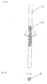
- FIGS. 6a and 6b show a side view and a sectional view through a shaft 52, to which the rotor yoke according to the invention can be applied.
- grooves 54 may be machined in the shaft 52 with which the projections 16 are engaged.
- the rotor yoke according to the invention has the advantage that it can be wound directly onto a shaft of the type shown in FIGS. 6 a, 6 b, so that the tips 22 of the projections 16 engage with the grooves 54. The rotor yoke can thus be mounted without any problems even if the diameter of the toothing base on the shaft is smaller than the outer diameter of the shaft.
- a body 50 is applied to the shaft 38, which has a toothing 56 which can be positively connected to the projections 16 of the return body.
- the body 50 may be made of plastic, for example, and be sprayed onto the shaft 38 or integrally formed with the shaft 38.
- the rotor body according to the invention has the great advantage that it can be constructed almost without waste of rotor laminations, which have the same rolling direction.
- the rotor laminations are first produced in the manner of a band and then bent in the band plane to form a ring.
- each annular rotor plate has the same preferred magnetic direction or, in other words, in each rotor region has the same preferred magnetic direction of the rotor material. This results in isotropic, homogeneous material properties of the rotor body and thus a quiet engine running.
- the rotor body according to the invention has the advantage that it can be connected without any problems with a shaft form-fitting, which has a toothing for receiving the tips of the projections, which has a tooth base with a smaller diameter than the shaft outer diameter.
Landscapes
- Engineering & Computer Science (AREA)
- Power Engineering (AREA)
- Manufacturing & Machinery (AREA)
- Iron Core Of Rotating Electric Machines (AREA)
- Manufacture Of Motors, Generators (AREA)
- Permanent Field Magnets Of Synchronous Machinery (AREA)
Applications Claiming Priority (1)
| Application Number | Priority Date | Filing Date | Title |
|---|---|---|---|
| DE102004047311A DE102004047311A1 (de) | 2004-09-29 | 2004-09-29 | Rotorkörper für einen Rotor einer elektrischen Maschine und Verfahren zur Herstellung eines Rotorkörpers |
Publications (2)
| Publication Number | Publication Date |
|---|---|
| EP1643617A2 true EP1643617A2 (fr) | 2006-04-05 |
| EP1643617A3 EP1643617A3 (fr) | 2007-06-20 |
Family
ID=34937647
Family Applications (1)
| Application Number | Title | Priority Date | Filing Date |
|---|---|---|---|
| EP05013672A Withdrawn EP1643617A3 (fr) | 2004-09-29 | 2005-06-24 | Corps de rotor et correspondant procédé de production pour une machine électrique |
Country Status (4)
| Country | Link |
|---|---|
| US (1) | US20060066166A1 (fr) |
| EP (1) | EP1643617A3 (fr) |
| JP (1) | JP2006121893A (fr) |
| DE (1) | DE102004047311A1 (fr) |
Cited By (1)
| Publication number | Priority date | Publication date | Assignee | Title |
|---|---|---|---|---|
| EP2942858A3 (fr) * | 2014-05-05 | 2015-12-23 | Siemens Aktiengesellschaft | Paquet de tôles de rotor |
Families Citing this family (9)
| Publication number | Priority date | Publication date | Assignee | Title |
|---|---|---|---|---|
| US7661185B2 (en) * | 2006-10-10 | 2010-02-16 | Canopy Technologies, Llc | Method for assembling rotor of permanent magnet motor |
| JP5877777B2 (ja) | 2012-09-26 | 2016-03-08 | 日立オートモティブシステムズ株式会社 | 回転電機、磁極ピース製造方法 |
| KR102268571B1 (ko) * | 2016-04-29 | 2021-06-24 | 삼성전자주식회사 | 공기조화기용 팬 모터 |
| CN106341018B (zh) * | 2016-09-26 | 2020-06-23 | 威灵(芜湖)电机制造有限公司 | 自启动电机转子、自启动永磁电机以及家用电器 |
| CN106341019B (zh) * | 2016-09-26 | 2019-11-22 | 威灵(芜湖)电机制造有限公司 | 自启动电机转子、自启动永磁电机以及家用电器 |
| CN106451981B (zh) * | 2016-09-26 | 2020-04-03 | 威灵(芜湖)电机制造有限公司 | 自启动电机转子、自启动永磁电机以及家用电器 |
| DE102018105738A1 (de) * | 2018-03-13 | 2019-09-19 | Bühler Motor GmbH | Rotor für einen Elektromotor und Herstellungsverfahren |
| WO2023108908A1 (fr) * | 2021-12-17 | 2023-06-22 | 淮安威灵电机制造有限公司 | Feuille de poinçonnage de rotor préfabriquée, ensemble rotor, moteur électrique et dispositif électrique |
| CN114189079A (zh) * | 2021-12-17 | 2022-03-15 | 淮安威灵电机制造有限公司 | 预制转子冲片、转子组件、电机和电器设备 |
Family Cites Families (10)
| Publication number | Priority date | Publication date | Assignee | Title |
|---|---|---|---|---|
| US1234567A (en) * | 1915-09-14 | 1917-07-24 | Edward J Quigley | Soft collar. |
| NL151580B (nl) * | 1968-10-31 | 1976-11-15 | Sev Alternateurs | Synchrone inductormachine. |
| DE2629532A1 (de) * | 1975-07-03 | 1977-01-27 | Sev Alternateurs | Verfahren und vorrichtung fuer einen stator oder rotor einer elektrischen rotationsmaschine |
| US4894905A (en) * | 1987-03-12 | 1990-01-23 | Mitsubishi Denki Kabushiki Kaisha | Method of forming armature core of electric rotating machine |
| DE4436626A1 (de) * | 1994-01-31 | 1996-01-04 | Baumueller Nuernberg Gmbh | Herstellungsverfahren für Ständer- oder Läuferbleche von elektrischen Maschinen und Synchronmotor |
| DE4423620A1 (de) * | 1994-07-06 | 1996-01-11 | Philips Patentverwaltung | Mittels Permanentmagneten erregbarer elektrischer Motor, insbesondere Innenläufer- oder Außenläufermotor |
| EP1109286B1 (fr) * | 1999-12-14 | 2005-03-02 | Mitsubishi Denki Kabushiki Kaisha | Noyau en fer pour machine électrique rotative et sa méthode de fabrication |
| JP2004153893A (ja) * | 2002-10-29 | 2004-05-27 | Toshiba Corp | 永久磁石型モータ及び磁極ヨークの製造方法 |
| DE60212406T2 (de) * | 2002-11-15 | 2007-02-01 | Minebea Co., Ltd. | Läufer mit eingebetteten Dauermagneten |
| EP1450462B1 (fr) * | 2003-02-18 | 2008-07-09 | Minebea Co., Ltd. | Rotor et stator de machine électrique avec des pulsations de couple réduites |
-
2004
- 2004-09-29 DE DE102004047311A patent/DE102004047311A1/de not_active Withdrawn
-
2005
- 2005-06-24 EP EP05013672A patent/EP1643617A3/fr not_active Withdrawn
- 2005-09-14 US US11/225,062 patent/US20060066166A1/en not_active Abandoned
- 2005-09-29 JP JP2005284708A patent/JP2006121893A/ja active Pending
Cited By (1)
| Publication number | Priority date | Publication date | Assignee | Title |
|---|---|---|---|---|
| EP2942858A3 (fr) * | 2014-05-05 | 2015-12-23 | Siemens Aktiengesellschaft | Paquet de tôles de rotor |
Also Published As
| Publication number | Publication date |
|---|---|
| DE102004047311A1 (de) | 2006-04-13 |
| US20060066166A1 (en) | 2006-03-30 |
| EP1643617A3 (fr) | 2007-06-20 |
| JP2006121893A (ja) | 2006-05-11 |
Similar Documents
| Publication | Publication Date | Title |
|---|---|---|
| EP2005555B1 (fr) | Stator pour machine electrique multiphasee et procede pour sa fabrication | |
| EP2507896B1 (fr) | Procédé de fabrication d'un stator de moteur électrique | |
| EP2017944B2 (fr) | Petit entraînement électrique ainsi qu'élément de reflux et son procédé de fabrication | |
| DE102007032872A1 (de) | Stator für Elektromotor | |
| DE102007024822B3 (de) | Verfahren zum Zusammenbau eines Stators für eine elektrische Maschine und Stator für eine elektrische Maschine | |
| EP1657801A2 (fr) | Rotor pour une machine électrique et procédé de fabrication d'un rotor | |
| AT522826A1 (de) | Rotor | |
| DE102017201178A1 (de) | Maschinenbauelement sowie Verfahren zum Herstellen eines Maschinenbauelements | |
| DE102012100332A1 (de) | Stator für eine rotierende elektrische Maschine und Verfahren zu seiner Herstellung | |
| EP3130057A1 (fr) | Module comprenant un noyau feuilleté pour une machine électrique, procédé de fabrication d'un tel module et machine électrique | |
| DE102004050374B4 (de) | Elektrische Maschine, insbesondere Gleichstrommotor | |
| EP2601726A2 (fr) | Dent d'enroulement et composant pour une machine électrique permettant de réduire les courants de foucault | |
| WO2004021548A1 (fr) | Empilage de toles pour machine electrique | |
| DE102004047311A1 (de) | Rotorkörper für einen Rotor einer elektrischen Maschine und Verfahren zur Herstellung eines Rotorkörpers | |
| EP2876789B1 (fr) | Procédé de fabrication d'un rotor | |
| DE102017102255A1 (de) | Stator für einen Elektromotor | |
| DE102005024653A1 (de) | Stator einer sich drehenden elektrischen Maschine und Herstellungsverfahren des Stators | |
| DE102005017517B4 (de) | Statoranordnung für eine elektrische Maschine und Verfahren zum Herstellen einer Statoranordnung | |
| EP1162720A2 (fr) | Tôles pour noyaux feuilletés de machines électriques tournantes et procédé de fabrication de telles tôles | |
| DE102021122126A1 (de) | Stator einer elektrischen Rotationsmaschine, Verfahren zur Herstellung des Stators sowie elektrische Rotationsmaschine | |
| DE102015222271A1 (de) | Rotor sowie elektrische Maschine | |
| DE102012006172A1 (de) | Elektromotor mit einem Rotor und Verfahren zum Herstellen eines Motors | |
| DE102021122128A1 (de) | Stator einer elektrischen Rotationsmaschine, Verfahren zur Herstellung des Stators sowie elektrische Rotationsmaschine | |
| DE102021122130A1 (de) | Stator einer elektrischen Rotationsmaschine, Verfahren zur Herstellung des Stators sowie elektrische Rotationsmaschine | |
| DE10327700A1 (de) | Blechpaket für eine elektrische Maschine |
Legal Events
| Date | Code | Title | Description |
|---|---|---|---|
| PUAI | Public reference made under article 153(3) epc to a published international application that has entered the european phase |
Free format text: ORIGINAL CODE: 0009012 |
|
| AK | Designated contracting states |
Kind code of ref document: A2 Designated state(s): AT BE BG CH CY CZ DE DK EE ES FI FR GB GR HU IE IS IT LI LT LU MC NL PL PT RO SE SI SK TR |
|
| AX | Request for extension of the european patent |
Extension state: AL BA HR LV MK YU |
|
| PUAL | Search report despatched |
Free format text: ORIGINAL CODE: 0009013 |
|
| AK | Designated contracting states |
Kind code of ref document: A3 Designated state(s): AT BE BG CH CY CZ DE DK EE ES FI FR GB GR HU IE IS IT LI LT LU MC NL PL PT RO SE SI SK TR |
|
| AX | Request for extension of the european patent |
Extension state: AL BA HR LV MK YU |
|
| AKX | Designation fees paid | ||
| STAA | Information on the status of an ep patent application or granted ep patent |
Free format text: STATUS: THE APPLICATION IS DEEMED TO BE WITHDRAWN |
|
| 18D | Application deemed to be withdrawn |
Effective date: 20071221 |
|
| REG | Reference to a national code |
Ref country code: DE Ref legal event code: 8566 |