EP1644197B1 - Dispositif d'ejection de fluides - Google Patents
Dispositif d'ejection de fluides Download PDFInfo
- Publication number
- EP1644197B1 EP1644197B1 EP04756240A EP04756240A EP1644197B1 EP 1644197 B1 EP1644197 B1 EP 1644197B1 EP 04756240 A EP04756240 A EP 04756240A EP 04756240 A EP04756240 A EP 04756240A EP 1644197 B1 EP1644197 B1 EP 1644197B1
- Authority
- EP
- European Patent Office
- Prior art keywords
- fluid
- inner layer
- layer
- outer layers
- nozzles
- Prior art date
- Legal status (The legal status is an assumption and is not a legal conclusion. Google has not performed a legal analysis and makes no representation as to the accuracy of the status listed.)
- Expired - Lifetime
Links
- 239000012530 fluid Substances 0.000 title claims abstract description 150
- 230000037361 pathway Effects 0.000 claims abstract description 43
- 239000010409 thin film Substances 0.000 claims description 27
- 239000000463 material Substances 0.000 claims description 15
- 239000000758 substrate Substances 0.000 claims description 15
- 238000000034 method Methods 0.000 claims description 13
- 238000010304 firing Methods 0.000 claims description 11
- 239000011521 glass Substances 0.000 claims description 11
- 230000004888 barrier function Effects 0.000 claims description 9
- 229910052751 metal Inorganic materials 0.000 claims description 5
- 239000011156 metal matrix composite Substances 0.000 claims description 4
- 229920000642 polymer Polymers 0.000 claims description 4
- 239000002184 metal Substances 0.000 claims description 3
- 239000012811 non-conductive material Substances 0.000 claims description 3
- OKTJSMMVPCPJKN-UHFFFAOYSA-N Carbon Chemical compound [C] OKTJSMMVPCPJKN-UHFFFAOYSA-N 0.000 claims description 2
- 229910052799 carbon Inorganic materials 0.000 claims description 2
- 229910010293 ceramic material Inorganic materials 0.000 claims description 2
- 239000002131 composite material Substances 0.000 claims description 2
- 230000003213 activating effect Effects 0.000 claims 1
- 239000000976 ink Substances 0.000 description 49
- 238000007641 inkjet printing Methods 0.000 description 7
- 238000003491 array Methods 0.000 description 3
- 238000007639 printing Methods 0.000 description 3
- VYPSYNLAJGMNEJ-UHFFFAOYSA-N Silicium dioxide Chemical compound O=[Si]=O VYPSYNLAJGMNEJ-UHFFFAOYSA-N 0.000 description 2
- 230000004913 activation Effects 0.000 description 2
- 238000004891 communication Methods 0.000 description 2
- 239000007788 liquid Substances 0.000 description 2
- 239000002905 metal composite material Substances 0.000 description 2
- 229910052715 tantalum Inorganic materials 0.000 description 2
- GUVRBAGPIYLISA-UHFFFAOYSA-N tantalum atom Chemical compound [Ta] GUVRBAGPIYLISA-UHFFFAOYSA-N 0.000 description 2
- 229920002799 BoPET Polymers 0.000 description 1
- 239000005041 Mylar™ Substances 0.000 description 1
- 229910052581 Si3N4 Inorganic materials 0.000 description 1
- 230000006978 adaptation Effects 0.000 description 1
- 238000004026 adhesive bonding Methods 0.000 description 1
- RVSGESPTHDDNTH-UHFFFAOYSA-N alumane;tantalum Chemical compound [AlH3].[Ta] RVSGESPTHDDNTH-UHFFFAOYSA-N 0.000 description 1
- 229910052782 aluminium Inorganic materials 0.000 description 1
- XAGFODPZIPBFFR-UHFFFAOYSA-N aluminium Chemical compound [Al] XAGFODPZIPBFFR-UHFFFAOYSA-N 0.000 description 1
- 230000002950 deficient Effects 0.000 description 1
- 238000010586 diagram Methods 0.000 description 1
- 239000010408 film Substances 0.000 description 1
- 230000009969 flowable effect Effects 0.000 description 1
- PCHJSUWPFVWCPO-UHFFFAOYSA-N gold Chemical compound [Au] PCHJSUWPFVWCPO-UHFFFAOYSA-N 0.000 description 1
- 229910052737 gold Inorganic materials 0.000 description 1
- 239000010931 gold Substances 0.000 description 1
- 238000009413 insulation Methods 0.000 description 1
- 229910001092 metal group alloy Inorganic materials 0.000 description 1
- 230000003287 optical effect Effects 0.000 description 1
- 238000002161 passivation Methods 0.000 description 1
- 229910021420 polycrystalline silicon Inorganic materials 0.000 description 1
- 230000003134 recirculating effect Effects 0.000 description 1
- HBMJWWWQQXIZIP-UHFFFAOYSA-N silicon carbide Chemical compound [Si+]#[C-] HBMJWWWQQXIZIP-UHFFFAOYSA-N 0.000 description 1
- 229910010271 silicon carbide Inorganic materials 0.000 description 1
- 235000012239 silicon dioxide Nutrition 0.000 description 1
- 239000000377 silicon dioxide Substances 0.000 description 1
- HQVNEWCFYHHQES-UHFFFAOYSA-N silicon nitride Chemical compound N12[Si]34N5[Si]62N3[Si]51N64 HQVNEWCFYHHQES-UHFFFAOYSA-N 0.000 description 1
Images



Classifications
-
- B—PERFORMING OPERATIONS; TRANSPORTING
- B41—PRINTING; LINING MACHINES; TYPEWRITERS; STAMPS
- B41J—TYPEWRITERS; SELECTIVE PRINTING MECHANISMS, i.e. MECHANISMS PRINTING OTHERWISE THAN FROM A FORME; CORRECTION OF TYPOGRAPHICAL ERRORS
- B41J2/00—Typewriters or selective printing mechanisms characterised by the printing or marking process for which they are designed
- B41J2/005—Typewriters or selective printing mechanisms characterised by the printing or marking process for which they are designed characterised by bringing liquid or particles selectively into contact with a printing material
- B41J2/01—Ink jet
- B41J2/135—Nozzles
- B41J2/14—Structure thereof only for on-demand ink jet heads
- B41J2/14016—Structure of bubble jet print heads
- B41J2/14072—Electrical connections, e.g. details on electrodes, connecting the chip to the outside...
-
- B—PERFORMING OPERATIONS; TRANSPORTING
- B41—PRINTING; LINING MACHINES; TYPEWRITERS; STAMPS
- B41J—TYPEWRITERS; SELECTIVE PRINTING MECHANISMS, i.e. MECHANISMS PRINTING OTHERWISE THAN FROM A FORME; CORRECTION OF TYPOGRAPHICAL ERRORS
- B41J2/00—Typewriters or selective printing mechanisms characterised by the printing or marking process for which they are designed
- B41J2/005—Typewriters or selective printing mechanisms characterised by the printing or marking process for which they are designed characterised by bringing liquid or particles selectively into contact with a printing material
- B41J2/01—Ink jet
- B41J2/135—Nozzles
- B41J2/14—Structure thereof only for on-demand ink jet heads
- B41J2/14016—Structure of bubble jet print heads
- B41J2/14032—Structure of the pressure chamber
- B41J2/1404—Geometrical characteristics
-
- B—PERFORMING OPERATIONS; TRANSPORTING
- B41—PRINTING; LINING MACHINES; TYPEWRITERS; STAMPS
- B41J—TYPEWRITERS; SELECTIVE PRINTING MECHANISMS, i.e. MECHANISMS PRINTING OTHERWISE THAN FROM A FORME; CORRECTION OF TYPOGRAPHICAL ERRORS
- B41J2/00—Typewriters or selective printing mechanisms characterised by the printing or marking process for which they are designed
- B41J2/005—Typewriters or selective printing mechanisms characterised by the printing or marking process for which they are designed characterised by bringing liquid or particles selectively into contact with a printing material
- B41J2/01—Ink jet
- B41J2/135—Nozzles
- B41J2/14—Structure thereof only for on-demand ink jet heads
- B41J2002/14379—Edge shooter
Definitions
- the ink is ejected from the cavity through the nozzle by a piezoelectric actuator on the side of the first plate remote from the central plate.
- the wall of the first plate is thin at the position of the piezoelectric actuator to allow the actuator to reduce the volume of the ink cavity to eject the ink.
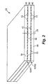
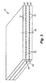
- printhead assembly 12 is a multi-layered assembly and includes outer layers 30 and 40, and at least one inner layer 50.
- Outer layers 30 and 40 have a face or side 32 and 42, respectively, and an edge 34 and 44, respectively, contiguous with the respective side 32 and 42.
- Outer layers 30 and 40 are positioned on opposite sides of inner layer 50 such that sides 32 and 42 face inner layer 50 and are adjacent inner layer 50. As such, inner layer 50 and outer layers 30 and 40 are stacked along an axis 29.
- nozzles 13 of rows 61 and 62 are substantially aligned. More specifically, each nozzle 13 of row 61 is substantially aligned with one nozzle 13 of row 62 along a print line oriented substantially parallel to axis 29.
- the embodiment of Figure 2 provides nozzle redundancy since fluid (or ink) can be ejected through multiple nozzles along a given print line. Thus, a defective or inoperative nozzle can be compensated for by another aligned nozzle.
- nozzle redundancy provides the ability to alternate nozzle activation amongst aligned nozzles.
- each fluid pathway 80 includes a fluid inlet 84, a fluid chamber 86, and a fluid outlet 88 such that fluid chamber 86 communicates with fluid inlet 84 and fluid outlet 88.
- Fluid inlet 84 communicates with a supply of fluid (or ink), as described below, and supplies fluid (or ink) to fluid chamber 86.
- Fluid outlet 88 communicates with fluid chamber 86 and, in one embodiment, forms a portion of a respective nozzle 13 when outer layers 30 and 40 are positioned on opposite sides of inner layer 50.
- each drop ejecting element 70 includes a firing resistor 72 formed within fluid chamber 86 of a respective fluid pathway 80.
- Firing resistor 72 includes, for example, a heater resistor which, when energized, heats fluid within fluid chamber 86 to produce a bubble within fluid chamber 86 and generate a droplet of fluid which is ejected through nozzle 13.
- a respective fluid chamber 86, firing resistor 72, and nozzle 13 form a drop generator of a respective drop ejecting element 70.
- outer layers 30 and 40 are joined to inner layer 50 at barriers 82.
- barriers 82 are formed of a photo-imageable polymer or glass
- outer layers 30 and 40 are bonded to inner layer 50 by temperature and pressure.
- Other suitable joining or bonding techniques can also be used to join outer layers 30 and 40 to inner layer 50.
- inner layers 251, 252, and 253 are joined together by glass frit bonding.
- glass frit material is deposited and patterned on inner layers 251, 252, and/or 253, and inner layers 251, 252, and 253 are bonded together under temperature and pressure.
- joints between inner layers 251, 252, and 253 are thermally matched.
- inner layers 251, 252, and 253 are joined together by anodic bonding.
- inner layers 251, 252, and 253 are brought into intimate contact and a voltage is applied across the layers.
- joints between inner layers 251, 252, and 253 are thermally matched and chemically inert since no additional material is used.
- inner layers 251, 252, and 253 are joined together by adhesive bonding. Other suitable joining or bonding techniques, however, can also be used to join inner layers 251, 252, and 253.
Landscapes
- Physics & Mathematics (AREA)
- Geometry (AREA)
- Particle Formation And Scattering Control In Inkjet Printers (AREA)
- Nozzles (AREA)
Abstract
Claims (14)
- Ensemble d'éjection de fluide, comprenant :au moins une couche interne (50, 150, 250) comprenant un passage de fluide (154, 254) défini à l'intérieur ; etdes première et seconde couches externes (30, 40) positionnées sur des côtés opposés de la au moins une couche interne,les première et seconde couches externes incluant chacune un substrat (90) et une structure à film mince (92) formée sur le substrat, et des éléments d'éjection de goutte (70, 72) formés sur la structure à film mince, la structure à film mince et les éléments d'éjection de goutte étant du côté de la couche externe adjacente à la au moins une couche interne,chaque couche externe définissant des chemins de fluide (80) communiquant avec les éléments d'éjection de goutte respectifs de la couche,dans lequel les chemins de fluide (80) des première et seconde couches externes communiquent avec le passage de fluide (154, 254) de la au moins une couche interne (50, 150, 250), etdans lequel la au moins une couche interne et les chemins de fluide de la première couche externe forment une première rangée (61) de buses (13), et la au moins une couche interne et les chemins de fluide de la seconde couche externe forment une seconde rangée (62) de buses (13).
- Ensemble d'éjection de fluide selon la revendication 1, dans lequel la au moins une couche interne inclut une couche interne unique (150) comprenant un premier côté (151) et un second côté (152) opposé au premier côté, dans lequel la première couche externe est adjacente au premier côté et la seconde couche externe est adjacente au second côté.
- Ensemble d'éjection de fluide selon la revendication 1, dans lequel la au moins une couche interne inclut une première couche interne (251) adjacente à la première couche externe, une deuxième couche interne (252) adjacente à la seconde couche externe, et une troisième couche interne (253) interposée entre la première couche interne et la deuxième couche interne.
- Ensemble d'éjection de fluide selon la revendication 1, dans lequel les éléments d'éjection de goutte de la première couche externe sont adaptés pour éjecter des gouttes de fluide à travers la première rangée de buses sensiblement parallèles audit premier côté de ladite première couche externe, et dans lequel les éléments d'éjection de goutte de la seconde couche externe sont adaptés pour éjecter des gouttes de fluide à travers la seconde rangée de buses sensiblement parallèles audit côté de la seconde couche externe.
- Ensemble d'éjection de fluide selon la revendication 1, dans lequel les première et seconde couches externes comprennent chacune un bord (34, 44) contigu avec ledit côté de celles-ci, dans lequel la première rangée de buses s'étend le long du bord de la première couche externe et la seconde rangée de buses s'étend le long du bord de la seconde couche externe.
- Ensemble d'éjection de fluide selon la revendication 1, dans lequel chacun des chemins de fluide des première et seconde couches externes inclut une entrée de fluide (84), une chambre de fluide (86) communiquant avec l'entrée de fluide, et une sortie de fluide (88) communiquant avec la chambre de fluide, et dans lequel les éléments d'éjection de goutte (70) sont formés au sein de chambres de fluide respectives de chemins respectifs parmi les chemins de fluide.
- Ensemble d'éjection de fluide selon la revendication 1, dans lequel le substrat de chacune des première et seconde couches externes inclut un matériau non conducteur, dans lequel le matériau non conducteur inclut un élément parmi le verre, un matériau céramique, un matériau composite de carbone, et un oxyde formé d'un élément parmi un métal et un matériau composite à matrice métallique.
- Ensemble d'éjection de fluide selon la revendication 1, dans lequel la structure à film mince inclut un circuit de commande (74) des éléments d'éjection de goutte, dans lequel le circuit de commande inclut des transistors à film mince.
- Ensemble d'éjection de fluide selon la revendication 1, dans lequel les première et seconde couches externes incluent chacune des barrières (82) formées entre les chemins de fluide, dans lequel les barrières sont formées sur la structure à film mince des première et seconde couches externes et sont formées d'un élément parmi un polymère photoimageable et du verre.
- Ensemble d'éjection de fluide selon l'une quelconque des revendications précédentes, dans lequel les éléments d'éjection de goutte sont des résistances d'allumage.
- Procédé de formation d'un ensemble d'éjection de fluide, le procédé comprenant les étapes suivantes :définition d'un passage de fluide (154, 254) dans au moins une couche interne (50, 150, 250) ;formation des première et seconde couches externes comprenant la formation d'une structure à film mince (92) sur un substrat de chacune des première et seconde couches, et la formation d'éléments d'éjection de goutte (70) sur un côté (32, 42) de la structure à film mince des première et seconde couches externes (30, 40) ;formation des chemins de fluide (80) dudit côté de chacune des première et seconde couches externes, comprenant le fait de faire communiquer les chemins de fluide avec les éléments d'éjection de goutte ; etpositionnement des première et seconde couches externes sur des côtés opposés de la au moins une couche interne avec ledit côté de chaque couche externe adjacente à la couche interne, comprenant le fait de faire communiquer les chemins de fluide des première et seconde couches externes avec le passage de fluide de la au moins une couche interne, etformation d'une première rangée (61) de buses (13), avec au moins une couche interne et les chemins de fluide de la première couche externe et formation d'une seconde rangée (62) de buses (13) avec la au moins une couche interne et les chemins de fluide de la seconde couche externe.
- Procédé selon la revendication 11, comprenant en outre l'étape consistant à former un circuit de commande dans la structure à film mince pour les éléments d'éjection de goutte, le circuit de commande comprenant des transistors à film mince.
- Procédé selon la revendication 11 ou 12, dans lequel les éléments d'éjection de goutte sont des résistances d'allumage.
- Procédé d'actionnement de l'ensemble d'éjection de fluide de l'une quelconque des revendications 1 à 10, le procédé comprenant les étapes suivantes :distribution d'un fluide dans les chemins de fluide (80) à travers le passage de fluide (154, 254) défini dans la au moins une couche interne (50) ; etactivation des éléments d'éjection de goutte formés sur la structure à film mince (92), éjectant ainsi des gouttes du fluide à travers la première rangée (61) de buses et à travers la seconde rangée (62) de buses (13).
Applications Claiming Priority (2)
| Application Number | Priority Date | Filing Date | Title |
|---|---|---|---|
| US10/613,471 US6890067B2 (en) | 2003-07-03 | 2003-07-03 | Fluid ejection assembly |
| PCT/US2004/020677 WO2005007412A1 (fr) | 2003-07-03 | 2004-06-25 | Dispositif d'ejection de fluides |
Publications (2)
| Publication Number | Publication Date |
|---|---|
| EP1644197A1 EP1644197A1 (fr) | 2006-04-12 |
| EP1644197B1 true EP1644197B1 (fr) | 2011-03-09 |
Family
ID=33552701
Family Applications (1)
| Application Number | Title | Priority Date | Filing Date |
|---|---|---|---|
| EP04756240A Expired - Lifetime EP1644197B1 (fr) | 2003-07-03 | 2004-06-25 | Dispositif d'ejection de fluides |
Country Status (9)
| Country | Link |
|---|---|
| US (1) | US6890067B2 (fr) |
| EP (1) | EP1644197B1 (fr) |
| JP (1) | JP2007527332A (fr) |
| CN (1) | CN100436139C (fr) |
| AR (1) | AR044998A1 (fr) |
| CL (1) | CL2004000953A1 (fr) |
| DE (1) | DE602004031735D1 (fr) |
| TW (1) | TWI296971B (fr) |
| WO (1) | WO2005007412A1 (fr) |
Families Citing this family (12)
| Publication number | Priority date | Publication date | Assignee | Title |
|---|---|---|---|---|
| US6890067B2 (en) | 2003-07-03 | 2005-05-10 | Hewlett-Packard Development Company, L.P. | Fluid ejection assembly |
| US20050206679A1 (en) * | 2003-07-03 | 2005-09-22 | Rio Rivas | Fluid ejection assembly |
| US7540593B2 (en) * | 2005-04-26 | 2009-06-02 | Hewlett-Packard Development Company, L.P. | Fluid ejection assembly |
| US7380914B2 (en) | 2005-04-26 | 2008-06-03 | Hewlett-Packard Development Company, L.P. | Fluid ejection assembly |
| US20070171261A1 (en) * | 2006-01-24 | 2007-07-26 | Samsung Electronics Co., Ltd | Array inkjet printhead |
| US8679694B2 (en) * | 2007-03-21 | 2014-03-25 | Societe Bic | Fluidic control system and method of manufacture |
| US8133629B2 (en) * | 2007-03-21 | 2012-03-13 | SOCIéTé BIC | Fluidic distribution system and related methods |
| ES2504215T3 (es) * | 2007-03-21 | 2014-10-08 | SOCIéTé BIC | Colector de fluido y procedimiento para el mismo |
| US7938513B2 (en) * | 2008-04-11 | 2011-05-10 | Lexmark International, Inc. | Heater chips with silicon die bonded on silicon substrate and methods of fabricating the heater chips |
| US8459779B2 (en) | 2008-04-11 | 2013-06-11 | Lexmark International, Inc. | Heater chips with silicon die bonded on silicon substrate, including offset wire bonding |
| US20100116423A1 (en) * | 2008-11-07 | 2010-05-13 | Zachary Justin Reitmeier | Micro-fluid ejection device and method for assembling a micro-fluid ejection device by wafer-to-wafer bonding |
| EP3160751B1 (fr) * | 2014-06-30 | 2020-02-12 | Hewlett-Packard Development Company, L.P. | Structure d'éjection de fluide |
Family Cites Families (51)
| Publication number | Priority date | Publication date | Assignee | Title |
|---|---|---|---|---|
| US4894464A (en) * | 1980-01-21 | 1990-01-16 | Pfizer Inc. | Branched amides of L-aspartyl-D-amino acid dipeptides |
| AT372651B (de) * | 1980-12-15 | 1983-11-10 | Philips Nv | Tintenstrahlschreibkopf und verfahren zur herstellung eines solchen tintenstrahlschreibkopfes |
| JPS57102366A (en) | 1980-12-18 | 1982-06-25 | Canon Inc | Ink jet head |
| EP0067653A3 (fr) * | 1981-06-13 | 1983-11-09 | Konica Corporation | Tête d'impression pour imprimante à jet d'encre |
| US4611219A (en) | 1981-12-29 | 1986-09-09 | Canon Kabushiki Kaisha | Liquid-jetting head |
| DE3361450D1 (en) | 1982-02-25 | 1986-01-23 | Boa Ag | Transducing and compensating device for angle variations in pipelines |
| US4438191A (en) | 1982-11-23 | 1984-03-20 | Hewlett-Packard Company | Monolithic ink jet print head |
| US4646110A (en) | 1982-12-29 | 1987-02-24 | Canon Kabushiki Kaisha | Liquid injection recording apparatus |
| JPH0624855B2 (ja) | 1983-04-20 | 1994-04-06 | キヤノン株式会社 | 液体噴射記録ヘッド |
| JPH0613219B2 (ja) | 1983-04-30 | 1994-02-23 | キヤノン株式会社 | インクジェットヘッド |
| JPH062416B2 (ja) | 1984-01-30 | 1994-01-12 | キヤノン株式会社 | 液体噴射記録ヘッドの製造方法 |
| US4730197A (en) | 1985-11-06 | 1988-03-08 | Pitney Bowes Inc. | Impulse ink jet system |
| US4680595A (en) | 1985-11-06 | 1987-07-14 | Pitney Bowes Inc. | Impulse ink jet print head and method of making same |
| US4965594A (en) | 1986-02-28 | 1990-10-23 | Canon Kabushiki Kaisha | Liquid jet recording head with laminated heat resistive layers on a support member |
| US4894664A (en) | 1986-04-28 | 1990-01-16 | Hewlett-Packard Company | Monolithic thermal ink jet printhead with integral nozzle and ink feed |
| US4695854A (en) | 1986-07-30 | 1987-09-22 | Pitney Bowes Inc. | External manifold for ink jet array |
| US4897668A (en) | 1987-03-02 | 1990-01-30 | Kabushiki Kaisha Toshiba | Apparatus for transferring ink from ink ribbon to a recording medium by applying heat to the medium, thereby recording data on the medium |
| US4823149A (en) * | 1987-03-09 | 1989-04-18 | Dataproducts Corporation | Ink jet apparatus employing plate-like structure |
| US5068674A (en) | 1988-06-07 | 1991-11-26 | Canon Kabushiki Kaisha | Liquid jet recording head stabilization |
| EP0345724B1 (fr) | 1988-06-07 | 1995-01-18 | Canon Kabushiki Kaisha | Tête d'enregistrement par jet de liquide et appareil d'enregistrement muni de cette tête |
| JP2849109B2 (ja) | 1989-03-01 | 1999-01-20 | キヤノン株式会社 | 液体噴射記録ヘッドの製造方法およびその方法により製造された液体噴射記録ヘッド |
| NL8903025A (nl) | 1989-12-08 | 1991-07-01 | Oce Nederland Bv | Stapelbare druppelgenerator voor een ink-jet printer. |
| US5469199A (en) | 1990-08-16 | 1995-11-21 | Hewlett-Packard Company | Wide inkjet printhead |
| US5132707A (en) | 1990-12-24 | 1992-07-21 | Xerox Corporation | Ink jet printhead |
| US5604519A (en) * | 1992-04-02 | 1997-02-18 | Hewlett-Packard Company | Inkjet printhead architecture for high frequency operation |
| US5825382A (en) | 1992-07-31 | 1998-10-20 | Francotyp-Postalia Ag & Co. | Edge-shooter ink jet print head and method for its manufacture |
| DE4225799A1 (de) | 1992-07-31 | 1994-02-03 | Francotyp Postalia Gmbh | Tintenstrahldruckkopf und Verfahren zu seiner Herstellung |
| JP3143549B2 (ja) | 1993-09-08 | 2001-03-07 | キヤノン株式会社 | 熱記録ヘッド用基体、該基体を用いたインクジェット記録ヘッド、インクジェットカートリッジ、インクジェット記録装置、及び記録ヘッドの駆動方法 |
| DE4336416A1 (de) | 1993-10-19 | 1995-08-24 | Francotyp Postalia Gmbh | Face-Shooter-Tintenstrahldruckkopf und Verfahren zu seiner Herstellung |
| JPH07137270A (ja) * | 1993-11-16 | 1995-05-30 | Canon Inc | インクジェット記録装置 |
| SG64335A1 (en) | 1993-12-28 | 1999-04-27 | Seiko Epson Corp | Ink jet recording head |
| US5565900A (en) | 1994-02-04 | 1996-10-15 | Hewlett-Packard Company | Unit print head assembly for ink-jet printing |
| DE4424771C1 (de) | 1994-07-05 | 1995-11-23 | Francotyp Postalia Gmbh | Tintendruckkopf aus einzelnen Tintendruckmodulen |
| DE59509149D1 (de) | 1994-08-03 | 2001-05-10 | Francotyp Postalia Gmbh | Anordnung für plattenförmige Piezoaktoren und Verfahren zu deren Herstellung |
| US5748214A (en) | 1994-08-04 | 1998-05-05 | Seiko Epson Corporation | Ink jet recording head |
| JP3196811B2 (ja) | 1994-10-17 | 2001-08-06 | セイコーエプソン株式会社 | 積層型インクジェット式記録ヘッド、及びその製造方法 |
| US6135586A (en) | 1995-10-31 | 2000-10-24 | Hewlett-Packard Company | Large area inkjet printhead |
| US6209991B1 (en) | 1997-03-04 | 2001-04-03 | Hewlett-Packard Company | Transition metal carbide films for applications in ink jet printheads |
| US6155674A (en) | 1997-03-04 | 2000-12-05 | Hewlett-Packard Company | Structure to effect adhesion between substrate and ink barrier in ink jet printhead |
| AUPO794697A0 (en) | 1997-07-15 | 1997-08-07 | Silverbrook Research Pty Ltd | A device (MEMS10) |
| US6286939B1 (en) | 1997-09-26 | 2001-09-11 | Hewlett-Packard Company | Method of treating a metal surface to increase polymer adhesion |
| US6024440A (en) * | 1998-01-08 | 2000-02-15 | Lexmark International, Inc. | Nozzle array for printhead |
| US5969736A (en) * | 1998-07-14 | 1999-10-19 | Hewlett-Packard Company | Passive pressure regulator for setting the pressure of a liquid to a predetermined pressure differential below a reference pressure |
| US6328428B1 (en) | 1999-04-22 | 2001-12-11 | Hewlett-Packard Company | Ink-jet printhead and method of producing same |
| JP2001001522A (ja) | 1999-06-23 | 2001-01-09 | Fuji Xerox Co Ltd | インクジェット記録ヘッド |
| KR20010045298A (ko) | 1999-11-04 | 2001-06-05 | 윤종용 | 잉크를 이용한 열압축방식의 유체분사장치 |
| US6652053B2 (en) | 2000-02-18 | 2003-11-25 | Canon Kabushiki Kaisha | Substrate for ink-jet printing head, ink-jet printing head, ink-jet cartridge, ink-jet printing apparatus, and method for detecting ink in ink-jet printing head |
| US6409323B1 (en) | 2000-05-23 | 2002-06-25 | Silverbrook Research Pty Ltd | Laminated ink distribution assembly for a printer |
| US6281912B1 (en) | 2000-05-23 | 2001-08-28 | Silverbrook Research Pty Ltd | Air supply arrangement for a printer |
| US6478404B2 (en) * | 2001-01-30 | 2002-11-12 | Hewlett-Packard Company | Ink jet printhead |
| US6890067B2 (en) | 2003-07-03 | 2005-05-10 | Hewlett-Packard Development Company, L.P. | Fluid ejection assembly |
-
2003
- 2003-07-03 US US10/613,471 patent/US6890067B2/en not_active Expired - Lifetime
-
2004
- 2004-03-26 TW TW093108367A patent/TWI296971B/zh not_active IP Right Cessation
- 2004-05-04 CL CL200400953A patent/CL2004000953A1/es unknown
- 2004-06-25 WO PCT/US2004/020677 patent/WO2005007412A1/fr not_active Ceased
- 2004-06-25 CN CNB2004800254229A patent/CN100436139C/zh not_active Expired - Fee Related
- 2004-06-25 DE DE602004031735T patent/DE602004031735D1/de not_active Expired - Lifetime
- 2004-06-25 EP EP04756240A patent/EP1644197B1/fr not_active Expired - Lifetime
- 2004-06-25 JP JP2006518699A patent/JP2007527332A/ja active Pending
- 2004-07-02 AR ARP040102339A patent/AR044998A1/es unknown
Also Published As
| Publication number | Publication date |
|---|---|
| US6890067B2 (en) | 2005-05-10 |
| CN1845824A (zh) | 2006-10-11 |
| US20050001886A1 (en) | 2005-01-06 |
| TW200513391A (en) | 2005-04-16 |
| JP2007527332A (ja) | 2007-09-27 |
| CN100436139C (zh) | 2008-11-26 |
| WO2005007412A1 (fr) | 2005-01-27 |
| AR044998A1 (es) | 2005-10-12 |
| CL2004000953A1 (es) | 2005-04-15 |
| TWI296971B (en) | 2008-05-21 |
| EP1644197A1 (fr) | 2006-04-12 |
| DE602004031735D1 (de) | 2011-04-21 |
Similar Documents
| Publication | Publication Date | Title |
|---|---|---|
| US6880926B2 (en) | Circulation through compound slots | |
| WO2014018008A1 (fr) | Dispositif d'éjection de fluide ayant une extension de film mince tolérante aux particules | |
| EP1644197B1 (fr) | Dispositif d'ejection de fluides | |
| EP2158088B1 (fr) | Collecteur de fluide pour dispositif d'éjection de fluide | |
| US20080197108A1 (en) | Fluid Ejection Assembly | |
| US7540593B2 (en) | Fluid ejection assembly | |
| US20050206679A1 (en) | Fluid ejection assembly | |
| US20210197561A1 (en) | Fluid ejection die |
Legal Events
| Date | Code | Title | Description |
|---|---|---|---|
| PUAI | Public reference made under article 153(3) epc to a published international application that has entered the european phase |
Free format text: ORIGINAL CODE: 0009012 |
|
| 17P | Request for examination filed |
Effective date: 20060131 |
|
| AK | Designated contracting states |
Kind code of ref document: A1 Designated state(s): DE FR GB |
|
| DAX | Request for extension of the european patent (deleted) | ||
| RBV | Designated contracting states (corrected) |
Designated state(s): DE FR GB |
|
| RIN1 | Information on inventor provided before grant (corrected) |
Inventor name: DIEST, KENNETH Inventor name: LEBRON, HECTOR Inventor name: HOCK, SCOTT W. Inventor name: CRIVELLI, PAUL |
|
| 17Q | First examination report despatched |
Effective date: 20090703 |
|
| GRAP | Despatch of communication of intention to grant a patent |
Free format text: ORIGINAL CODE: EPIDOSNIGR1 |
|
| GRAS | Grant fee paid |
Free format text: ORIGINAL CODE: EPIDOSNIGR3 |
|
| GRAA | (expected) grant |
Free format text: ORIGINAL CODE: 0009210 |
|
| AK | Designated contracting states |
Kind code of ref document: B1 Designated state(s): DE FR GB |
|
| REG | Reference to a national code |
Ref country code: GB Ref legal event code: FG4D |
|
| REF | Corresponds to: |
Ref document number: 602004031735 Country of ref document: DE Date of ref document: 20110421 Kind code of ref document: P |
|
| REG | Reference to a national code |
Ref country code: DE Ref legal event code: R096 Ref document number: 602004031735 Country of ref document: DE Effective date: 20110421 |
|
| PLBE | No opposition filed within time limit |
Free format text: ORIGINAL CODE: 0009261 |
|
| STAA | Information on the status of an ep patent application or granted ep patent |
Free format text: STATUS: NO OPPOSITION FILED WITHIN TIME LIMIT |
|
| 26N | No opposition filed |
Effective date: 20111212 |
|
| REG | Reference to a national code |
Ref country code: DE Ref legal event code: R097 Ref document number: 602004031735 Country of ref document: DE Effective date: 20111212 |
|
| REG | Reference to a national code |
Ref country code: FR Ref legal event code: PLFP Year of fee payment: 13 |
|
| REG | Reference to a national code |
Ref country code: FR Ref legal event code: PLFP Year of fee payment: 14 |
|
| REG | Reference to a national code |
Ref country code: FR Ref legal event code: PLFP Year of fee payment: 15 |
|
| PGFP | Annual fee paid to national office [announced via postgrant information from national office to epo] |
Ref country code: DE Payment date: 20200519 Year of fee payment: 17 Ref country code: FR Payment date: 20200520 Year of fee payment: 17 |
|
| PGFP | Annual fee paid to national office [announced via postgrant information from national office to epo] |
Ref country code: GB Payment date: 20200525 Year of fee payment: 17 |
|
| REG | Reference to a national code |
Ref country code: DE Ref legal event code: R119 Ref document number: 602004031735 Country of ref document: DE |
|
| GBPC | Gb: european patent ceased through non-payment of renewal fee |
Effective date: 20210625 |
|
| PG25 | Lapsed in a contracting state [announced via postgrant information from national office to epo] |
Ref country code: GB Free format text: LAPSE BECAUSE OF NON-PAYMENT OF DUE FEES Effective date: 20210625 Ref country code: DE Free format text: LAPSE BECAUSE OF NON-PAYMENT OF DUE FEES Effective date: 20220101 |
|
| PG25 | Lapsed in a contracting state [announced via postgrant information from national office to epo] |
Ref country code: FR Free format text: LAPSE BECAUSE OF NON-PAYMENT OF DUE FEES Effective date: 20210630 |