EP1644219B1 - Scheinwerfereinheit für kraftfahrzeug und entsprechendes fahrzeug - Google Patents
Scheinwerfereinheit für kraftfahrzeug und entsprechendes fahrzeug Download PDFInfo
- Publication number
- EP1644219B1 EP1644219B1 EP04767577A EP04767577A EP1644219B1 EP 1644219 B1 EP1644219 B1 EP 1644219B1 EP 04767577 A EP04767577 A EP 04767577A EP 04767577 A EP04767577 A EP 04767577A EP 1644219 B1 EP1644219 B1 EP 1644219B1
- Authority
- EP
- European Patent Office
- Prior art keywords
- support
- headlamp
- vehicle
- bumper
- projector
- Prior art date
- Legal status (The legal status is an assumption and is not a legal conclusion. Google has not performed a legal analysis and makes no representation as to the accuracy of the status listed.)
- Expired - Lifetime
Links
Images

Classifications
-
- B—PERFORMING OPERATIONS; TRANSPORTING
- B60—VEHICLES IN GENERAL
- B60Q—ARRANGEMENT OF SIGNALLING OR LIGHTING DEVICES, THE MOUNTING OR SUPPORTING THEREOF OR CIRCUITS THEREFOR, FOR VEHICLES IN GENERAL
- B60Q1/00—Arrangement of optical signalling or lighting devices, the mounting or supporting thereof or circuits therefor
- B60Q1/02—Arrangement of optical signalling or lighting devices, the mounting or supporting thereof or circuits therefor the devices being primarily intended to illuminate the way ahead or to illuminate other areas of way or environments
- B60Q1/04—Arrangement of optical signalling or lighting devices, the mounting or supporting thereof or circuits therefor the devices being primarily intended to illuminate the way ahead or to illuminate other areas of way or environments the devices being headlights
- B60Q1/0408—Arrangement of optical signalling or lighting devices, the mounting or supporting thereof or circuits therefor the devices being primarily intended to illuminate the way ahead or to illuminate other areas of way or environments the devices being headlights built into the vehicle body, e.g. details concerning the mounting of the headlamps on the vehicle body
- B60Q1/0433—Arrangement of optical signalling or lighting devices, the mounting or supporting thereof or circuits therefor the devices being primarily intended to illuminate the way ahead or to illuminate other areas of way or environments the devices being headlights built into the vehicle body, e.g. details concerning the mounting of the headlamps on the vehicle body the housing being fastened onto the vehicle body using screws
-
- B—PERFORMING OPERATIONS; TRANSPORTING
- B60—VEHICLES IN GENERAL
- B60Q—ARRANGEMENT OF SIGNALLING OR LIGHTING DEVICES, THE MOUNTING OR SUPPORTING THEREOF OR CIRCUITS THEREFOR, FOR VEHICLES IN GENERAL
- B60Q1/00—Arrangement of optical signalling or lighting devices, the mounting or supporting thereof or circuits therefor
- B60Q1/02—Arrangement of optical signalling or lighting devices, the mounting or supporting thereof or circuits therefor the devices being primarily intended to illuminate the way ahead or to illuminate other areas of way or environments
- B60Q1/04—Arrangement of optical signalling or lighting devices, the mounting or supporting thereof or circuits therefor the devices being primarily intended to illuminate the way ahead or to illuminate other areas of way or environments the devices being headlights
- B60Q1/0408—Arrangement of optical signalling or lighting devices, the mounting or supporting thereof or circuits therefor the devices being primarily intended to illuminate the way ahead or to illuminate other areas of way or environments the devices being headlights built into the vehicle body, e.g. details concerning the mounting of the headlamps on the vehicle body
- B60Q1/0475—Arrangement of optical signalling or lighting devices, the mounting or supporting thereof or circuits therefor the devices being primarily intended to illuminate the way ahead or to illuminate other areas of way or environments the devices being headlights built into the vehicle body, e.g. details concerning the mounting of the headlamps on the vehicle body with provisions for pre-mounting, for temporary holding the headlamp before or during final mounting
-
- B—PERFORMING OPERATIONS; TRANSPORTING
- B60—VEHICLES IN GENERAL
- B60Q—ARRANGEMENT OF SIGNALLING OR LIGHTING DEVICES, THE MOUNTING OR SUPPORTING THEREOF OR CIRCUITS THEREFOR, FOR VEHICLES IN GENERAL
- B60Q1/00—Arrangement of optical signalling or lighting devices, the mounting or supporting thereof or circuits therefor
- B60Q1/02—Arrangement of optical signalling or lighting devices, the mounting or supporting thereof or circuits therefor the devices being primarily intended to illuminate the way ahead or to illuminate other areas of way or environments
- B60Q1/04—Arrangement of optical signalling or lighting devices, the mounting or supporting thereof or circuits therefor the devices being primarily intended to illuminate the way ahead or to illuminate other areas of way or environments the devices being headlights
- B60Q1/0491—Shock absorbing devices therefor
-
- B—PERFORMING OPERATIONS; TRANSPORTING
- B60—VEHICLES IN GENERAL
- B60R—VEHICLES, VEHICLE FITTINGS, OR VEHICLE PARTS, NOT OTHERWISE PROVIDED FOR
- B60R19/00—Wheel guards; Radiator guards, e.g. grilles; Obstruction removers; Fittings damping bouncing force in collisions
- B60R19/02—Bumpers, i.e. impact receiving or absorbing members for protecting vehicles or fending off blows from other vehicles or objects
- B60R19/24—Arrangements for mounting bumpers on vehicles
-
- B—PERFORMING OPERATIONS; TRANSPORTING
- B60—VEHICLES IN GENERAL
- B60R—VEHICLES, VEHICLE FITTINGS, OR VEHICLE PARTS, NOT OTHERWISE PROVIDED FOR
- B60R19/00—Wheel guards; Radiator guards, e.g. grilles; Obstruction removers; Fittings damping bouncing force in collisions
- B60R19/02—Bumpers, i.e. impact receiving or absorbing members for protecting vehicles or fending off blows from other vehicles or objects
- B60R19/18—Bumpers, i.e. impact receiving or absorbing members for protecting vehicles or fending off blows from other vehicles or objects characterised by the cross-section; Means within the bumper to absorb impact
- B60R2019/1886—Bumper fascias and fastening means therefor
Definitions
- the invention relates to a projector block comprising a projector and a projector support, the motor vehicle including a shield. It also relates to a vehicle equipped with such a projector block.
- the projector block according to the invention is particularly intended for the front of a vehicle.
- a first device is to fix on the front cross member of the vehicle a complex shaped part on which the front portion of the underside of the projector can be fixed, the rear part of the projector being fixed to a fixed upper structure of the vehicle.
- This device has the disadvantage of requiring many delicate settings for proper fixation and orientation of the projectors.
- the shield of the vehicle is then attached to the vehicle by its central portion and its side parts, but is not supported at the headlights. This lack of support can be troublesome for the resistance of the shield and the projectors during a shock and also produces an unsightly irregular space between the shield and the projectors.
- Another device consists in producing premounted front faces comprising the shield and the integral headlamps of a reference piece intended to be fixed to the front structure of the vehicle, as described in the document FR-2 783 797 .
- the document FR-2 827 251 also discloses a device of this kind, in which the reference piece presses the shield against the underside of the projector, without space. This device allows a fast and simple assembly but can however be used only for vehicles designed for this purpose and can not be adapted to vehicles that do not have pre-assembled front faces.
- a headlamp according to the preamble of claim 1 is known from EP-A-1232932 .
- the invention aims to overcome these disadvantages by providing a projector block that can be easily attached to a vehicle, without being part of a front face in block, and which also provides a shield support now the latter at a substantially constant distance of the projector.
- a first object of the invention relates to a projector block for a motor vehicle. According to the features of claim 1.
- the shield support means extends continuously over at least a portion of the periphery of the support body. In another embodiment, the shield support means are regularly distributed over a part of the periphery of the support body. This latter configuration makes it possible to pass between the support means of the projector equipment, such as a nozzle, or other elements of the vehicle. These embodiments provide effective shield support at the projector.
- the shield support means extend along and below the visible portion of the edge of the underside of the projector. A constant space between the shield and the projector is thus provided at the visible portion of the projector, improving the aesthetics of the assembly.
- the shield support means have at least one bearing surface on which the shield rests, which extends substantially parallel to the underside of the projector, below it.
- the shield support means have at least one support lug rigidly connected to the support body and whose upper part forms said at least one bearing surface.
- said at least one bearing surface of the support lug may be a substantially flat surface, the largest of which dimension extends along the periphery of the support body. A very stable support of the shield is then obtained.
- the shield support means have a plurality of support lugs whose respective bearing surfaces are substantially flat surfaces whose largest dimension extends substantially perpendicular to the periphery of the support body.
- the body of the support is provided with means for positioning and fixing the headlamp, and fastening means on the vehicle.
- the positioning and fixing means of the projector facilitate the placement of the projector on its support, which reduces the assembly time and limit adjustments.
- the positioning and fixing means comprise positioning tongues adapted to be inserted in corresponding parts of the lower face of the projector and fixing tongues adapted to be fixed rigidly on the lower face of the projector at its part. back. It is thus sufficient to separate the fixing tabs to move the projector relative to its support and then to remove it completely from the support. This displacement can be used advantageously when changing the bulbs of the projector, to facilitate access to the latter without completely disassemble the projector of its support.
- Another object of the invention relates to a vehicle comprising a shield having a substantially horizontal upper edge secured to a substantially vertical wall and a projector block according to the invention.
- the fixing means of the projector support on the vehicle comprise at least one bracket on a fixed upper structure of the vehicle and at least one bracket on a lower fixed structure of the vehicle. This two-point fixation of the structure ensures a good stability to the projector support.
- the vehicle comprising a spar forming a lower fixed structure, said at least one fixing lug is connected to the spar by an inverted L-shaped part, the small part of which wing is secured to said at least one bracket and the large wing is secured to the spar.
- a hubcap element is fixed on the upper edge of the shield so as to close the space between the shield and the projector in the vertical direction, to improve the aesthetics of the front of the vehicle.
- the shield support means are shaped so as to be at a predetermined distance from the front wall of the shield in a direction substantially perpendicular to the periphery of the support body in a substantially horizontal plane, and so as to be at a distance from predetermined distance from the projector in the same direction so that the edge of the shield is distant from the projector.
- This configuration has several advantages.
- the spaces between the front wall of the shield and the support on the one hand, and between the edge of the shield and the projector on the other hand allow the shield to move during weak impacts without damaging the support and / or the projector .
- the space between the edge of the shield and the projector plays the role of a clearance space of the projector: the latter can be advanced to the shield support means, thus freeing up space on its rear face, for example, to change bulbs or other items.
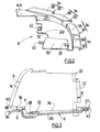
- the figure 1 represents a projector block 2 comprising a light projector 4 and a projector holder 6.
- This projector block 2 is intended for the front of a motor vehicle of which only the front shield 8 is shown.
- the latter is for example fixed in known manner at the body of the vehicle by its lateral extremities and at the front crossbar by its median part.
- the shield 8 has a substantially horizontal upper edge 10 visible on the figure 4 , secured to a substantially vertical wall 12.
- the projector 4 comprises an external mirror 14 comprising a front wall 16 and a substantially horizontal lower edge 18 in the mounted position ( figure 4 ).
- the outer glass 14 is hermetically secured to a housing 20 having a rear base 22 and a base 24 substantially horizontal.
- the lower edge is located in a plane above the base 24.
- the "lower face of the projector" is the lower edge 18 of the window 14 and the base 24 of the housing 20.
- the underside of the projector may be formed solely of the base 24 of the housing, for example when the ice 14 has no lower edge 18.
- the projector 4 comprises at least two fastening tabs 26 on fixed parts of the vehicle.
- three fastening lugs 26 integral with the housing 20 are provided.
- the housing 20 also has at least two brackets 27 on the projector support 6, located near its base 24 ( figure 3 ). These lugs 26, 27 comprise an orifice for fixing them by screws or the like to the vehicle or the support.
- the tabs 26 are for example fixed on the upper front cross member and on the vehicle body (not shown).
- the base 24 of the projector also has positioning means with respect to the projector support 6.
- These positioning means consist of at least two housings 28, only one of which is visible on the figure 4 . They are oriented in the same direction, for example in the longitudinal direction of the vehicle, and are able to cooperate with corresponding tabs disposed on the support 6.
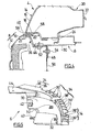
- the projector support 6 is described with reference to the figure 2 . It comprises a body 30 adapted to receive and support at least partly the underside of the projector.
- the body 30 supports the base 24 of the projector. Its shape is therefore substantially complementary to the shape of the base 24.
- Two tongues 32 cut in the thickness of the body 30 and protruding above its surface, form positioning means of the projector. They are designed so that they can be engaged in the slots 28 of the base 24 of the projector ( figure 3 ).
- the tongues 32 are engaged in the recesses 28 in the longitudinal direction of the vehicle, towards the front of the latter.
- the body 30 is provided with shield support means 34 for at least partially supporting the upper edge 10 of the shield.
- these means comprise lugs 36, rigidly secured to the periphery of the body 30, and each having a substantially flat upper bearing surface 38.
- the tabs 36 are shaped so that when the projector is in place on the support 6, the bearing surfaces 38 extend at a substantially constant distance d below the underside of the projector in a substantially vertical direction. ( figure 3 ).
- These bearing surfaces 38 serve to support the edge 10 of the shield, as shown in FIG. figure 4 .
- the largest dimension of these bearing surfaces 38 extends along the periphery of the body 30.
- the tabs 36 preferably extend along and below the visible portion 40 of the edge of the lower face of the projector 4. They are preferably distributed regularly along this length. part 40, but can form a single continuous leg along it.
- the body 30 also comprises means for fixing the headlamp, such as, for example, fixing lugs 42 provided with orifices arranged on the rear part of the body 30 ( figure 2 ). These lugs 42 are fixed to the lugs 27 of the headlamp, by screwing or the like ( figure 3 ).
- the body 30 also has fastening means on fixed parts of the vehicle. These means comprise, for example, at least one leg 44 substantially horizontal or vertical provided with an orifice, and fixed on the upper lateral part of the vehicle body (not shown). They also comprise at least one lug 46 located on the underside of the body 30, parallel to the latter ( figure 4 ), away from the tab 44.
- This lug 46 is fixed on a lower fixed part of the vehicle.
- the lug 46 is fixed to a longitudinal member 48 of the vehicle via a piece 50 in the shape of an inverted L.
- the small wing of the piece 50 is thus inserted between the tab 46 and the body 30 and fixed thereto by means of a screw 52 or the like, while the large wing of the piece 50 is fixed to the spar 48 by means of of a screw 54 or the like.
- the tabs 44 and 46 thus ensure a good attachment of the projector support 6 relative to the vehicle, and limit the transmission of forces to the projector.
- the shield support means 34 comprise a tab 36, as described with reference to the figure 2 and tabs 36 'extending in a substantially vertical direction.
- the bearing surfaces 38 'of the shield are then formed by the upper edge of the tabs 36' and are substantially flat surfaces whose largest dimension extends perpendicularly to the periphery of the body.
- some tabs 36 ' may optionally be interconnected by material bridges (not shown).
- legs 36 or 36 'spaced allows to provide spaces for passing equipment of the vehicle.
- a trim member 56 may be attached to the upper edge 10 of the shield ( figures 1 and 4 ). Vertical fastening screws or clips of this hubcap on the shield are then arranged between the tabs 36 or 36 '. Such hubcap member at least partially obturates the distance d between the shield and the projector, for aesthetic purposes.
- the shield support means 34 are configured so that, when the projector is fixed on the support 6 and the shield 8 rests on the tabs 36, 36 ', spaces d1 and d2 are respectively formed between the front wall 12 of the shield and the foremost part of the legs 36, 36 ', and between the end 58 of the upper edge of the shield and the projector, in a direction substantially perpendicular to the periphery of the body of the support ( figure 4 ).
- These spaces make it possible, during weak shocks, to prevent the shield from damaging the support and the projector. They are for example chosen to withstand shocks of the order of 4 Km / h, and may, for example, be about 15 mm.
- a space d2 makes it possible, once the fastening tabs 27 and 26 of the headlamp have been detached, to move the projector 4 from the distance d2 in the direction of the tongues 32 towards the front of the vehicle. as represented by the arrows F on the figure 3 .
- the new position of the projector 4, shown in dashed lines in this figure, makes it possible to free a space on the bottom side 22 of the projector housing, and to access more easily either the projector or other elements of the vehicle arranged behind the projector. projector.
- the mounting of the headlamp unit and the shield is carried out as follows.
- the projector support 6 is first attached to the vehicle by means of the brackets 44 and 46. The spacing between them ensures a very stable attachment of the support.
- the shield 8 is then put in place, its upper edge 10 resting on the shield support means 34 of the support 6.
- a trim element 56 may be fixed on the upper edge 10.
- the projector 4 is then placed on the support of projector 6 so that the housing 28 of the base of the projector are aligned with the tongues 32 of the support 6. The latter are then engaged in the housing 28.
- the projector 4 is finally fixed on the support by means of the brackets 27 and on the vehicle by means of the fixing lugs 26.
- the means for positioning the support relative to the projector can be provided.
- the tabs can be arranged on the projector.
- the number and position of the various fastening tabs may also vary depending on the structure of each vehicle.
Landscapes
- Engineering & Computer Science (AREA)
- Mechanical Engineering (AREA)
- Lighting Device Outwards From Vehicle And Optical Signal (AREA)
Claims (13)
- Scheinwerfereinheit (2) für ein Kraftfahrzeug, die einen Scheinwerfer (4) mit einer Unterseite und eine Scheinwerferhalterung (6) aufweist, wobei das Fahrzeug einen Stoßfänger (8) aufweist, der einen im Wesentlichen waagrechten oberen Rand (10) mit einem Ende (58) hat, welcher fest mit einer im Wesentlichen senkrechten Vorderwand (12) verbunden ist, wobei
die Scheinwerferhalterung (6) einen Körper (30) enthält, der die Unterseite des Scheinwerfers aufnimmt und zumindest teilweise hält, wobei der Körper mit Stoßfängerhalterungsmitteln (34) versehen ist, die zumindest teilweise den oberen Rand des Stoßfängers (10) unter der Unterseite des Scheinwerfers in einem in einer im Wesentlichen senkrechten Richtung im Wesentlichen konstanten Abstand (d) von der Unterseite halten können, wobei die Scheinwerfereinheit (2) Mittel (44, 46, 26) zur Befestigung am Fahrzeug aufweist, und
wobei
der Körper (30) der Halterung mit Mitteln zum Positionieren (32) und zur Befestigung (42) des Scheinwerfers und mit Mitteln (44, 46) zur Befestigung am Fahrzeug versehen ist,
dadurch gekennzeichnet, dass die Mittel (34) zur Halterung des Stoßfängers so gestaltet sind, dass sie sich in einem vorbestimmten Abstand (d1) zur Vorderwand (12) des Stoßfängers in einer Richtung im Wesentlichen lotrecht zum Umriss des Körpers (30) der Halterung in einer im Wesentlichen waagrechten Ebene befinden, und dass sie sich in einem vorbestimmten Abstand zum Scheinwerfer in der gleichen Richtung befinden, so dass das Ende (58) des oberen Rands (10) des Stoßfängers einen Abstand (d2) zum Scheinwerfer (4) hat, wodurch eine Verschiebung des Stoßfängers und des Scheinwerfers erlaubt wird. - Scheinwerfereinheit nach Anspruch 1, dadurch gekennzeichnet, dass die Stoßfängerhalterungsmittel (34) sich durchgehend über mindestens einen Teil des Umrisses des Körpers (30) der Halterung erstrecken.
- Scheinwerfereinheit nach Anspruch 1, dadurch gekennzeichnet, dass die Stoßfängerhalterungsmittel (34) gleichmäßig über einen Teil des Umrisses des Körpers (30) der Halterung verteilt sind.
- Scheinwerfereinheit nach einem der Ansprüche 1 bis 3, dadurch gekennzeichnet, dass die Stoßfängerhalterungsmittel (34) sich entlang und unter dem sichtbaren Bereich (40) des Rands der Unterseite des Scheinwerfers erstrecken.
- Scheinwerfereinheit nach einem der Ansprüche 1 bis 4, dadurch gekennzeichnet, dass die Stoßfängerhalterungsmittel (34) mindestens eine Auflagefläche (38, 38') haben, auf der der Stoßfänger aufliegt, die sich parallel zur Unterseite des Scheinwerfers unter dieser erstreckt.
- Scheinwerfereinheit nach Anspruch 5, dadurch gekennzeichnet, dass die Stoßfängerhalterungsmittel (34) mindestens eine Stützlasche (36, 36') haben, die steif mit dem Körper der Halterung verbunden ist und deren oberer Bereich die mindestens eine Auflagefläche (38, 38') bildet.
- Scheinwerfereinheit nach Anspruch 6, dadurch gekennzeichnet, dass die mindestens eine Auflagefläche (38) der Stützlasche (36) eine im Wesentlichen ebene Fläche ist, deren größte Abmessung sich entlang des Umrisses des Körpers der Halterung erstreckt.
- Scheinwerfereinheit nach Anspruch 6, dadurch gekennzeichnet, dass die Stoßfängerhalterungsmittel (34) mehrere Stützlaschen (36') haben, deren Auflageflächen (38') im Wesentlichen ebene Flächen sind, deren größte Abmessung sich im Wesentlichen lotrecht zum Umriss des Körpers der Halterung erstreckt.
- Scheinwerfereinheit nach einem der Ansprüche 1 bis 7, dadurch gekennzeichnet, dass die Positionier-und Befestigungsmittel Positionierzungen (32), die in entsprechende Bereiche (28) der Unterseite des Scheinwerfers eingefügt werden können, und Befestigungszungen (42) aufweisen, die starr an der Unterseite des Scheinwerfers in Höhe seines hinteren Bereichs befestigt werden können.
- Fahrzeug, das einen Stoßfänger (8), der einen im Wesentlichen waagrechten oberen Rand (10) hat, der fest mit einer im Wesentlichen senkrechten Vorderwand (12) verbunden ist, und eine Scheinwerfereinheit (2) nach einem der Ansprüche 1 bis 9 aufweist.
- Fahrzeug nach Anspruch 10, dadurch gekennzeichnet, dass die Mittel zur Befestigung der Scheinwerferhalterung am Fahrzeug mindestens eine Lasche (44) zur Befestigung an einer oberen festen Struktur des Fahrzeugs und mindestens eine Lasche (46) zur Befestigung an einer unteren festen Struktur des Fahrzeugs aufweisen.
- Fahrzeug nach Anspruch 11, wobei das Fahrzeug einen eine untere feste Struktur bildenden Längsträger (48) aufweist, dadurch gekennzeichnet, dass die mindestens eine Befestigungslasche (46) mit dem Längsträger (48) durch ein Bauteil (50) in Form eines umgedrehten L verbunden ist, dessen kleiner Schenkel fest mit der mindestens einen Befestigungslasche (46) und dessen großer Schenkel fest mit dem Längsträger (48) verbunden ist.
- Fahrzeug nach einem der Ansprüche 10 bis 12, dadurch gekennzeichnet, dass ein Zierleistenelement (56) am oberen Rand (10) des Stoßfängers so befestigt ist, dass der Raum zwischen dem Stoßfänger und dem Scheinwerfer in senkrechter Richtung verschlossen wird.
Applications Claiming Priority (2)
| Application Number | Priority Date | Filing Date | Title |
|---|---|---|---|
| FR0308609A FR2857645B1 (fr) | 2003-07-15 | 2003-07-15 | Bloc projecteur pour vehicule automobile, et vehicule correspondant. |
| PCT/FR2004/001741 WO2005007449A1 (fr) | 2003-07-15 | 2004-07-05 | Bloc projecteur pour vehicule automobile, et vehicule corresppondant |
Publications (2)
| Publication Number | Publication Date |
|---|---|
| EP1644219A1 EP1644219A1 (de) | 2006-04-12 |
| EP1644219B1 true EP1644219B1 (de) | 2009-08-26 |
Family
ID=33548136
Family Applications (1)
| Application Number | Title | Priority Date | Filing Date |
|---|---|---|---|
| EP04767577A Expired - Lifetime EP1644219B1 (de) | 2003-07-15 | 2004-07-05 | Scheinwerfereinheit für kraftfahrzeug und entsprechendes fahrzeug |
Country Status (6)
| Country | Link |
|---|---|
| EP (1) | EP1644219B1 (de) |
| JP (1) | JP4614211B2 (de) |
| AT (1) | ATE440752T1 (de) |
| DE (1) | DE602004022814D1 (de) |
| FR (1) | FR2857645B1 (de) |
| WO (1) | WO2005007449A1 (de) |
Cited By (2)
| Publication number | Priority date | Publication date | Assignee | Title |
|---|---|---|---|---|
| DE102020121799A1 (de) | 2020-08-19 | 2022-02-24 | Bayerische Motoren Werke Aktiengesellschaft | Verbindungselement zur Anbindung einer Scheinwerfereinheit an eine Stoßfängerverkleidung, Fronteinheit sowie Fahrzeug |
| FR3145521A1 (fr) * | 2023-02-08 | 2024-08-09 | Psa Automobiles Sa | Support sous feu arrière de véhicule automobile |
Families Citing this family (19)
| Publication number | Priority date | Publication date | Assignee | Title |
|---|---|---|---|---|
| DE102004012551B4 (de) * | 2004-03-15 | 2018-06-14 | Volkswagen Ag | Vorrichtung zum Befestigen eines Fahrzeugscheinwerfers und eines Anbauteils |
| FR2873652B1 (fr) * | 2004-08-02 | 2008-01-25 | Faurecia Bloc Avant | Ensemble de partie avant d'un vehicule automobile |
| DE102005009926B4 (de) * | 2005-03-04 | 2018-11-08 | Volkswagen Ag | Montageanordnung für eine Stoßfängerverkleidung an einem Fahrzeug |
| DE102005045086A1 (de) * | 2005-09-21 | 2007-04-12 | Volkswagen Ag | Befestigungsvorrichtung für eine Stoßstangen-Leuchten-Baueinheit |
| FR2891798B1 (fr) * | 2005-10-06 | 2009-05-01 | Plastic Omnium Cie | Support pour bloc optique de vehicule automobile. |
| DE102006023803A1 (de) | 2006-05-20 | 2007-11-22 | GM Global Technology Operations, Inc., Detroit | Stoßfängeranordnung in einem oder für ein Kraftfahrzeug |
| FR2903646B1 (fr) * | 2006-07-13 | 2009-04-17 | Peugeot Citroen Automobiles Sa | Dispositif de positionnement d'elements de carrosserie d'une face avant d'un vehicule automobile et vehicule automobile comportant une telle face avant. |
| DE102007008489A1 (de) * | 2007-02-19 | 2008-09-04 | Hbpo Gmbh | Frontendmodul für Fahrzeuge |
| DE102007035279A1 (de) * | 2007-07-27 | 2009-01-29 | Audi Ag | Vorrichtung zur Anbringung eines Frontscheinwerfers an einer Karosserie |
| JP5075557B2 (ja) * | 2007-09-28 | 2012-11-21 | スタンレー電気株式会社 | 車両用灯具の車体取付け構成 |
| FR2923433B1 (fr) * | 2007-11-12 | 2010-04-23 | Faurecia Bloc Avant | Peau de pare-choc pour un module avant de vehicule automobile et vehicule automobile associe |
| DE102008024428A1 (de) * | 2008-05-20 | 2009-11-26 | Dr. Ing. H.C. F. Porsche Aktiengesellschaft | Baugruppe zur Lagerung eines Scheinwerfers eines Kraftfahrzeugs sowie Verfahren zur Bildung der Baugruppe |
| FR2951675A1 (fr) * | 2009-10-28 | 2011-04-29 | Peugeot Citroen Automobiles Sa | Partie arriere de vehicule automobile comprenant deux feux arrieres et des supports pour soutenir le pare-choc |
| DE102013210981A1 (de) * | 2013-06-12 | 2014-12-18 | Bayerische Motoren Werke Aktiengesellschaft | Verbindungsanordnung |
| DE102014005060A1 (de) * | 2014-04-05 | 2015-10-08 | Daimler Ag | Stoßfängerverkleidung für einen Kraftwagen |
| FR3040666B1 (fr) * | 2015-09-03 | 2021-02-19 | Peugeot Citroen Automobiles Sa | Bloc optique pour vehicule automobile comportant un boitier dote d’organes de support de la peau de pare-chocs. |
| FR3094293B1 (fr) * | 2019-03-29 | 2021-03-05 | Psa Automobiles Sa | Dispositif et procédé de montage isostatique sur la caisse d'un véhicule automobile, d'un projecteur lumineux et d'un parechoc montés sur un support commun. |
| FR3118132A1 (fr) | 2020-12-22 | 2022-06-24 | Psa Automobiles Sa | Dispositif de protection contre les chocs à bloc optique intégré en environnement contraint, pour un véhicule |
| FR3158681B1 (fr) * | 2024-01-31 | 2026-03-06 | Renault Sas | Bloc projecteur muni de moyens de support d’un bouclier de véhicule automobile |
Family Cites Families (11)
| Publication number | Priority date | Publication date | Assignee | Title |
|---|---|---|---|---|
| FR2481218A1 (fr) * | 1980-04-25 | 1981-10-30 | Peugeot | Element d'extremite pour carrosserie de vehicule automobile |
| DE4142582A1 (de) * | 1991-12-21 | 1993-06-24 | Porsche Ag | Stossfaenger fuer fahrzeuge, insbesondere kraftfahrzeuge |
| JP3151587B2 (ja) * | 1994-06-03 | 2001-04-03 | 日産車体株式会社 | ヘッドランプとフロントバンパーとの位置決め構造 |
| JPH0858498A (ja) * | 1994-08-24 | 1996-03-05 | Daihatsu Motor Co Ltd | 車両用バンパの支持構造 |
| FR2783797B1 (fr) | 1998-09-30 | 2000-12-29 | Ecia Equip Composants Ind Auto | Vehicule automobile, bloc avant pour ce vehicule et procede de montage de ce vehicule |
| JP4066061B2 (ja) * | 1999-05-27 | 2008-03-26 | 関東自動車工業株式会社 | バンパ取付構造 |
| JP2001225708A (ja) * | 2000-02-16 | 2001-08-21 | Koito Mfg Co Ltd | 車両用灯具・バンパ間接続構造 |
| FR2820706B1 (fr) * | 2001-02-15 | 2003-05-16 | Faurecia Ind | Ensemble de bloc avant de vehicule automobile comportant un dispositif ameliore de fixation des composants, et vehicule equipe d'un tel ensemble |
| FR2827251B1 (fr) | 2001-07-10 | 2003-10-31 | Peguform France | Vehicule comprenant une piece de maintien d'elements de carrosserie de la face avant du vehicule |
| FR2852285B1 (fr) * | 2003-03-11 | 2005-06-10 | Peugeot Citroen Automobiles Sa | Procede et ensemble de montage d'un pare-chocs et d'au moins un dispositif d'eclairage d'un vehicule automobile dans des positions adjacentes |
| FR2855487B1 (fr) * | 2003-06-02 | 2005-08-26 | Faurecia Ind | Ensemble de bloc-avant de vehicule automobile comportant des moyens d'auto-ajustement de la position des blocs optiques, platine amovible de reglage prevue a cet effet, et procede de montage d'un tel bloc avant |
-
2003
- 2003-07-15 FR FR0308609A patent/FR2857645B1/fr not_active Expired - Fee Related
-
2004
- 2004-07-05 JP JP2006519950A patent/JP4614211B2/ja not_active Expired - Fee Related
- 2004-07-05 DE DE602004022814T patent/DE602004022814D1/de not_active Expired - Lifetime
- 2004-07-05 AT AT04767577T patent/ATE440752T1/de not_active IP Right Cessation
- 2004-07-05 WO PCT/FR2004/001741 patent/WO2005007449A1/fr not_active Ceased
- 2004-07-05 EP EP04767577A patent/EP1644219B1/de not_active Expired - Lifetime
Cited By (2)
| Publication number | Priority date | Publication date | Assignee | Title |
|---|---|---|---|---|
| DE102020121799A1 (de) | 2020-08-19 | 2022-02-24 | Bayerische Motoren Werke Aktiengesellschaft | Verbindungselement zur Anbindung einer Scheinwerfereinheit an eine Stoßfängerverkleidung, Fronteinheit sowie Fahrzeug |
| FR3145521A1 (fr) * | 2023-02-08 | 2024-08-09 | Psa Automobiles Sa | Support sous feu arrière de véhicule automobile |
Also Published As
| Publication number | Publication date |
|---|---|
| FR2857645B1 (fr) | 2005-09-16 |
| JP2007516119A (ja) | 2007-06-21 |
| FR2857645A1 (fr) | 2005-01-21 |
| EP1644219A1 (de) | 2006-04-12 |
| ATE440752T1 (de) | 2009-09-15 |
| DE602004022814D1 (de) | 2009-10-08 |
| WO2005007449A1 (fr) | 2005-01-27 |
| JP4614211B2 (ja) | 2011-01-19 |
Similar Documents
| Publication | Publication Date | Title |
|---|---|---|
| EP1644219B1 (de) | Scheinwerfereinheit für kraftfahrzeug und entsprechendes fahrzeug | |
| EP0720935B1 (de) | Vorrichtung zur präzisen Positionierung eines Stossfängers zu einem Kotflügelteil eines Fahrzeuges | |
| EP1232932B1 (de) | Fronteinheit für ein Kraftfahrzeug, und verbesserte Befestigung für Anbauteile, Kraftfahrzeug ausgerüstet mit einer derartigen Befestigung | |
| EP1544035A1 (de) | Vorderer Karosserieaufbau eines Kraftfahrzeuges mit verbesserten Befestigungs- und Lagejustiermitteln, und Kraftfahrzeug ausgestattet mit einem solchen Aufbau | |
| FR2981318A1 (fr) | Support de projecteur pour vehicule automobile et projecteur correspondant | |
| EP2102032B1 (de) | Stützmittelanordnung für einen kraftfahrzeugstossfänger | |
| FR3025756A1 (fr) | Glissieres pour sieges de vehicules, siege de vehicule comportant une telle glissiere | |
| EP1623879B1 (de) | Kraftfahrzeugfrontendmodul | |
| EP1634800B1 (de) | Fronteinheit für ein Kraftfahrzeug | |
| EP2216587A1 (de) | Signalleuchte für Kraftfahrzeug mit Abstandhaltersystem für Lichtleiter | |
| WO2003006302A1 (fr) | Vehicule comprenant une piece de maintien d'element de carrosserie de la face avant du vehicule. | |
| EP1758767B1 (de) | Scheinwerfereinheit für ein kraftfahrzeug | |
| EP1252045B1 (de) | Vorrichtung zur befestigung der seitenschenkel einer stossstange | |
| WO2011095715A2 (fr) | Element pour dispositif d'agencement et dispositif d'agencement pourvu d'un tel element | |
| EP1127740B1 (de) | Kraftfahrzeugscheinwerfer mit Maske und Reflektor | |
| EP3381747A1 (de) | Befestigungselement eines scheinwerfers eines fahrzeugs | |
| EP1475268B1 (de) | Anordnung zur Positionierung und Befestigung eines Ausstatungsteils in einem Kraftfahrzeug | |
| EP1877285B1 (de) | Anordnung für kraftfahrzeugstossdämpfer | |
| EP4380820B1 (de) | Lichtmodul zur befestigung an einer lichtvorrichtung eines kraftfahrzeugs | |
| EP1127741B1 (de) | Kfz-Scheinwerfer mit Maske und Korrektur | |
| FR2917057A1 (fr) | Module de tableau de bord comprenant un dispositif de climatisation | |
| EP1610005B1 (de) | Klammer für die Befestigung einer Schraube an Teile eines Automobils | |
| FR3065703A1 (fr) | Agencement pour vehicule automobile comprenant un element de carrosserie et un dispositif d’eclairage et/ou de signalisation implante dans ledit element de carrosserie. | |
| FR2796535A1 (fr) | Dispositif de support d'etageres reglable en hauteur a creneaux | |
| EP3966496A1 (de) | Tageslichtsignalisierungsmodul für kraftfahrzeuge und beleuchtungs- und signalgebungsanordnung mit diesem modul |
Legal Events
| Date | Code | Title | Description |
|---|---|---|---|
| PUAI | Public reference made under article 153(3) epc to a published international application that has entered the european phase |
Free format text: ORIGINAL CODE: 0009012 |
|
| 17P | Request for examination filed |
Effective date: 20060110 |
|
| AK | Designated contracting states |
Kind code of ref document: A1 Designated state(s): AT BE BG CH CY CZ DE DK EE ES FI FR GB GR HU IE IT LI LU MC NL PL PT RO SE SI SK TR |
|
| DAX | Request for extension of the european patent (deleted) | ||
| 17Q | First examination report despatched |
Effective date: 20070619 |
|
| GRAP | Despatch of communication of intention to grant a patent |
Free format text: ORIGINAL CODE: EPIDOSNIGR1 |
|
| GRAS | Grant fee paid |
Free format text: ORIGINAL CODE: EPIDOSNIGR3 |
|
| GRAA | (expected) grant |
Free format text: ORIGINAL CODE: 0009210 |
|
| AK | Designated contracting states |
Kind code of ref document: B1 Designated state(s): AT BE BG CH CY CZ DE DK EE ES FI FR GB GR HU IE IT LI LU MC NL PL PT RO SE SI SK TR |
|
| REG | Reference to a national code |
Ref country code: GB Ref legal event code: FG4D Free format text: NOT ENGLISH |
|
| REG | Reference to a national code |
Ref country code: CH Ref legal event code: EP |
|
| REG | Reference to a national code |
Ref country code: IE Ref legal event code: FG4D Free format text: LANGUAGE OF EP DOCUMENT: FRENCH |
|
| REF | Corresponds to: |
Ref document number: 602004022814 Country of ref document: DE Date of ref document: 20091008 Kind code of ref document: P |
|
| PG25 | Lapsed in a contracting state [announced via postgrant information from national office to epo] |
Ref country code: SE Free format text: LAPSE BECAUSE OF FAILURE TO SUBMIT A TRANSLATION OF THE DESCRIPTION OR TO PAY THE FEE WITHIN THE PRESCRIBED TIME-LIMIT Effective date: 20090826 Ref country code: FI Free format text: LAPSE BECAUSE OF FAILURE TO SUBMIT A TRANSLATION OF THE DESCRIPTION OR TO PAY THE FEE WITHIN THE PRESCRIBED TIME-LIMIT Effective date: 20090826 Ref country code: AT Free format text: LAPSE BECAUSE OF FAILURE TO SUBMIT A TRANSLATION OF THE DESCRIPTION OR TO PAY THE FEE WITHIN THE PRESCRIBED TIME-LIMIT Effective date: 20090826 |
|
| NLV1 | Nl: lapsed or annulled due to failure to fulfill the requirements of art. 29p and 29m of the patents act | ||
| PG25 | Lapsed in a contracting state [announced via postgrant information from national office to epo] |
Ref country code: PL Free format text: LAPSE BECAUSE OF FAILURE TO SUBMIT A TRANSLATION OF THE DESCRIPTION OR TO PAY THE FEE WITHIN THE PRESCRIBED TIME-LIMIT Effective date: 20090826 Ref country code: NL Free format text: LAPSE BECAUSE OF FAILURE TO SUBMIT A TRANSLATION OF THE DESCRIPTION OR TO PAY THE FEE WITHIN THE PRESCRIBED TIME-LIMIT Effective date: 20090826 Ref country code: SI Free format text: LAPSE BECAUSE OF FAILURE TO SUBMIT A TRANSLATION OF THE DESCRIPTION OR TO PAY THE FEE WITHIN THE PRESCRIBED TIME-LIMIT Effective date: 20090826 |
|
| PG25 | Lapsed in a contracting state [announced via postgrant information from national office to epo] |
Ref country code: BG Free format text: LAPSE BECAUSE OF FAILURE TO SUBMIT A TRANSLATION OF THE DESCRIPTION OR TO PAY THE FEE WITHIN THE PRESCRIBED TIME-LIMIT Effective date: 20091126 Ref country code: PT Free format text: LAPSE BECAUSE OF FAILURE TO SUBMIT A TRANSLATION OF THE DESCRIPTION OR TO PAY THE FEE WITHIN THE PRESCRIBED TIME-LIMIT Effective date: 20091228 Ref country code: CY Free format text: LAPSE BECAUSE OF FAILURE TO SUBMIT A TRANSLATION OF THE DESCRIPTION OR TO PAY THE FEE WITHIN THE PRESCRIBED TIME-LIMIT Effective date: 20090826 |
|
| REG | Reference to a national code |
Ref country code: IE Ref legal event code: FD4D |
|
| PG25 | Lapsed in a contracting state [announced via postgrant information from national office to epo] |
Ref country code: CZ Free format text: LAPSE BECAUSE OF FAILURE TO SUBMIT A TRANSLATION OF THE DESCRIPTION OR TO PAY THE FEE WITHIN THE PRESCRIBED TIME-LIMIT Effective date: 20090826 Ref country code: ES Free format text: LAPSE BECAUSE OF FAILURE TO SUBMIT A TRANSLATION OF THE DESCRIPTION OR TO PAY THE FEE WITHIN THE PRESCRIBED TIME-LIMIT Effective date: 20091207 Ref country code: EE Free format text: LAPSE BECAUSE OF FAILURE TO SUBMIT A TRANSLATION OF THE DESCRIPTION OR TO PAY THE FEE WITHIN THE PRESCRIBED TIME-LIMIT Effective date: 20090826 Ref country code: DK Free format text: LAPSE BECAUSE OF FAILURE TO SUBMIT A TRANSLATION OF THE DESCRIPTION OR TO PAY THE FEE WITHIN THE PRESCRIBED TIME-LIMIT Effective date: 20090826 Ref country code: IE Free format text: LAPSE BECAUSE OF FAILURE TO SUBMIT A TRANSLATION OF THE DESCRIPTION OR TO PAY THE FEE WITHIN THE PRESCRIBED TIME-LIMIT Effective date: 20090826 Ref country code: RO Free format text: LAPSE BECAUSE OF FAILURE TO SUBMIT A TRANSLATION OF THE DESCRIPTION OR TO PAY THE FEE WITHIN THE PRESCRIBED TIME-LIMIT Effective date: 20090826 |
|
| PG25 | Lapsed in a contracting state [announced via postgrant information from national office to epo] |
Ref country code: SK Free format text: LAPSE BECAUSE OF FAILURE TO SUBMIT A TRANSLATION OF THE DESCRIPTION OR TO PAY THE FEE WITHIN THE PRESCRIBED TIME-LIMIT Effective date: 20090826 |
|
| PLBE | No opposition filed within time limit |
Free format text: ORIGINAL CODE: 0009261 |
|
| STAA | Information on the status of an ep patent application or granted ep patent |
Free format text: STATUS: NO OPPOSITION FILED WITHIN TIME LIMIT |
|
| 26N | No opposition filed |
Effective date: 20100527 |
|
| PG25 | Lapsed in a contracting state [announced via postgrant information from national office to epo] |
Ref country code: GR Free format text: LAPSE BECAUSE OF FAILURE TO SUBMIT A TRANSLATION OF THE DESCRIPTION OR TO PAY THE FEE WITHIN THE PRESCRIBED TIME-LIMIT Effective date: 20091127 |
|
| BERE | Be: lapsed |
Owner name: RENAULT S.A.S. Effective date: 20100731 |
|
| PG25 | Lapsed in a contracting state [announced via postgrant information from national office to epo] |
Ref country code: MC Free format text: LAPSE BECAUSE OF NON-PAYMENT OF DUE FEES Effective date: 20100731 |
|
| REG | Reference to a national code |
Ref country code: CH Ref legal event code: PL |
|
| PG25 | Lapsed in a contracting state [announced via postgrant information from national office to epo] |
Ref country code: IT Free format text: LAPSE BECAUSE OF FAILURE TO SUBMIT A TRANSLATION OF THE DESCRIPTION OR TO PAY THE FEE WITHIN THE PRESCRIBED TIME-LIMIT Effective date: 20090826 |
|
| PG25 | Lapsed in a contracting state [announced via postgrant information from national office to epo] |
Ref country code: LI Free format text: LAPSE BECAUSE OF NON-PAYMENT OF DUE FEES Effective date: 20100731 Ref country code: CH Free format text: LAPSE BECAUSE OF NON-PAYMENT OF DUE FEES Effective date: 20100731 |
|
| PG25 | Lapsed in a contracting state [announced via postgrant information from national office to epo] |
Ref country code: BE Free format text: LAPSE BECAUSE OF NON-PAYMENT OF DUE FEES Effective date: 20100731 |
|
| PG25 | Lapsed in a contracting state [announced via postgrant information from national office to epo] |
Ref country code: LU Free format text: LAPSE BECAUSE OF NON-PAYMENT OF DUE FEES Effective date: 20100705 Ref country code: HU Free format text: LAPSE BECAUSE OF FAILURE TO SUBMIT A TRANSLATION OF THE DESCRIPTION OR TO PAY THE FEE WITHIN THE PRESCRIBED TIME-LIMIT Effective date: 20100227 |
|
| PG25 | Lapsed in a contracting state [announced via postgrant information from national office to epo] |
Ref country code: TR Free format text: LAPSE BECAUSE OF FAILURE TO SUBMIT A TRANSLATION OF THE DESCRIPTION OR TO PAY THE FEE WITHIN THE PRESCRIBED TIME-LIMIT Effective date: 20090826 |
|
| REG | Reference to a national code |
Ref country code: FR Ref legal event code: PLFP Year of fee payment: 12 |
|
| REG | Reference to a national code |
Ref country code: FR Ref legal event code: PLFP Year of fee payment: 13 |
|
| REG | Reference to a national code |
Ref country code: FR Ref legal event code: PLFP Year of fee payment: 14 |
|
| REG | Reference to a national code |
Ref country code: FR Ref legal event code: PLFP Year of fee payment: 15 |
|
| PGFP | Annual fee paid to national office [announced via postgrant information from national office to epo] |
Ref country code: FR Payment date: 20210727 Year of fee payment: 18 |
|
| PGFP | Annual fee paid to national office [announced via postgrant information from national office to epo] |
Ref country code: DE Payment date: 20210721 Year of fee payment: 18 Ref country code: GB Payment date: 20210721 Year of fee payment: 18 |
|
| REG | Reference to a national code |
Ref country code: DE Ref legal event code: R119 Ref document number: 602004022814 Country of ref document: DE |
|
| GBPC | Gb: european patent ceased through non-payment of renewal fee |
Effective date: 20220705 |
|
| PG25 | Lapsed in a contracting state [announced via postgrant information from national office to epo] |
Ref country code: FR Free format text: LAPSE BECAUSE OF NON-PAYMENT OF DUE FEES Effective date: 20220731 |
|
| PG25 | Lapsed in a contracting state [announced via postgrant information from national office to epo] |
Ref country code: GB Free format text: LAPSE BECAUSE OF NON-PAYMENT OF DUE FEES Effective date: 20220705 Ref country code: DE Free format text: LAPSE BECAUSE OF NON-PAYMENT OF DUE FEES Effective date: 20230201 |