EP1644705B1 - System und verfahren zum betreiben eines flussprozesses - Google Patents
System und verfahren zum betreiben eines flussprozesses Download PDFInfo
- Publication number
- EP1644705B1 EP1644705B1 EP04777027.6A EP04777027A EP1644705B1 EP 1644705 B1 EP1644705 B1 EP 1644705B1 EP 04777027 A EP04777027 A EP 04777027A EP 1644705 B1 EP1644705 B1 EP 1644705B1
- Authority
- EP
- European Patent Office
- Prior art keywords
- flow
- fluid
- signal
- pipe
- pressure
- Prior art date
- Legal status (The legal status is an assumption and is not a legal conclusion. Google has not performed a legal analysis and makes no representation as to the accuracy of the status listed.)
- Expired - Lifetime
Links
- 238000000034 method Methods 0.000 title claims description 149
- 230000008569 process Effects 0.000 title claims description 102
- 239000012530 fluid Substances 0.000 claims description 99
- 239000000203 mixture Substances 0.000 claims description 46
- 238000012545 processing Methods 0.000 claims description 28
- 230000001902 propagating effect Effects 0.000 claims description 21
- 230000004044 response Effects 0.000 claims description 21
- 230000036541 health Effects 0.000 claims description 17
- 238000012544 monitoring process Methods 0.000 claims description 16
- 238000011156 evaluation Methods 0.000 claims description 15
- 239000007788 liquid Substances 0.000 claims description 14
- 238000007435 diagnostic evaluation Methods 0.000 claims description 11
- 239000002033 PVDF binder Substances 0.000 claims description 8
- 229920002981 polyvinylidene fluoride Polymers 0.000 claims description 8
- 239000000463 material Substances 0.000 claims description 5
- 238000006073 displacement reaction Methods 0.000 claims description 4
- 230000003287 optical effect Effects 0.000 claims description 4
- 239000002002 slurry Substances 0.000 claims description 4
- 238000005111 flow chemistry technique Methods 0.000 claims 1
- 239000002245 particle Substances 0.000 description 37
- 239000007789 gas Substances 0.000 description 25
- 230000006870 function Effects 0.000 description 19
- 239000012071 phase Substances 0.000 description 15
- 230000002123 temporal effect Effects 0.000 description 14
- 238000005259 measurement Methods 0.000 description 10
- 238000010586 diagram Methods 0.000 description 9
- 230000000694 effects Effects 0.000 description 9
- 239000000446 fuel Substances 0.000 description 9
- 239000003245 coal Substances 0.000 description 7
- 238000005070 sampling Methods 0.000 description 7
- 230000000875 corresponding effect Effects 0.000 description 6
- 230000008859 change Effects 0.000 description 5
- 230000003595 spectral effect Effects 0.000 description 5
- 238000011144 upstream manufacturing Methods 0.000 description 5
- 230000003044 adaptive effect Effects 0.000 description 4
- 230000006399 behavior Effects 0.000 description 4
- 230000001276 controlling effect Effects 0.000 description 4
- 238000001514 detection method Methods 0.000 description 4
- 239000006185 dispersion Substances 0.000 description 4
- 239000007787 solid Substances 0.000 description 4
- 230000008901 benefit Effects 0.000 description 3
- 230000005540 biological transmission Effects 0.000 description 3
- 230000006854 communication Effects 0.000 description 3
- 238000004891 communication Methods 0.000 description 3
- 230000006835 compression Effects 0.000 description 3
- 238000007906 compression Methods 0.000 description 3
- 238000013154 diagnostic monitoring Methods 0.000 description 3
- 238000000605 extraction Methods 0.000 description 3
- 239000000835 fiber Substances 0.000 description 3
- 238000012423 maintenance Methods 0.000 description 3
- 238000012986 modification Methods 0.000 description 3
- 230000004048 modification Effects 0.000 description 3
- 230000035945 sensitivity Effects 0.000 description 3
- 238000003491 array Methods 0.000 description 2
- 235000013361 beverage Nutrition 0.000 description 2
- 229920001577 copolymer Polymers 0.000 description 2
- 238000000354 decomposition reaction Methods 0.000 description 2
- 230000007423 decrease Effects 0.000 description 2
- 230000001934 delay Effects 0.000 description 2
- 238000003745 diagnosis Methods 0.000 description 2
- 238000011068 loading method Methods 0.000 description 2
- 238000004377 microelectronic Methods 0.000 description 2
- 238000010248 power generation Methods 0.000 description 2
- 238000007670 refining Methods 0.000 description 2
- 239000000126 substance Substances 0.000 description 2
- 238000004065 wastewater treatment Methods 0.000 description 2
- XLYOFNOQVPJJNP-UHFFFAOYSA-N water Substances O XLYOFNOQVPJJNP-UHFFFAOYSA-N 0.000 description 2
- 238000012935 Averaging Methods 0.000 description 1
- 239000004593 Epoxy Substances 0.000 description 1
- 229910000831 Steel Inorganic materials 0.000 description 1
- 230000001133 acceleration Effects 0.000 description 1
- 230000005534 acoustic noise Effects 0.000 description 1
- 239000000853 adhesive Substances 0.000 description 1
- 230000001070 adhesive effect Effects 0.000 description 1
- 230000003466 anti-cipated effect Effects 0.000 description 1
- 230000007175 bidirectional communication Effects 0.000 description 1
- 238000009530 blood pressure measurement Methods 0.000 description 1
- 230000003139 buffering effect Effects 0.000 description 1
- 230000015556 catabolic process Effects 0.000 description 1
- 230000001427 coherent effect Effects 0.000 description 1
- 230000002596 correlated effect Effects 0.000 description 1
- 230000007812 deficiency Effects 0.000 description 1
- 238000006731 degradation reaction Methods 0.000 description 1
- 230000005284 excitation Effects 0.000 description 1
- 238000001914 filtration Methods 0.000 description 1
- 229920002313 fluoropolymer Polymers 0.000 description 1
- 239000004811 fluoropolymer Substances 0.000 description 1
- 239000003292 glue Substances 0.000 description 1
- 238000009434 installation Methods 0.000 description 1
- 230000003993 interaction Effects 0.000 description 1
- 239000007791 liquid phase Substances 0.000 description 1
- 230000007257 malfunction Effects 0.000 description 1
- 238000013507 mapping Methods 0.000 description 1
- 238000000691 measurement method Methods 0.000 description 1
- 238000002156 mixing Methods 0.000 description 1
- 238000005457 optimization Methods 0.000 description 1
- 229920000642 polymer Polymers 0.000 description 1
- 238000004886 process control Methods 0.000 description 1
- 230000010349 pulsation Effects 0.000 description 1
- 239000010453 quartz Substances 0.000 description 1
- 230000008439 repair process Effects 0.000 description 1
- VYPSYNLAJGMNEJ-UHFFFAOYSA-N silicon dioxide Inorganic materials O=[Si]=O VYPSYNLAJGMNEJ-UHFFFAOYSA-N 0.000 description 1
- 238000010183 spectrum analysis Methods 0.000 description 1
- 230000003068 static effect Effects 0.000 description 1
- 239000010959 steel Substances 0.000 description 1
- 239000000725 suspension Substances 0.000 description 1
- 238000012546 transfer Methods 0.000 description 1
- 230000007704 transition Effects 0.000 description 1
- 239000011800 void material Substances 0.000 description 1
- 239000002023 wood Substances 0.000 description 1
Images






Classifications
-
- G—PHYSICS
- G01—MEASURING; TESTING
- G01F—MEASURING VOLUME, VOLUME FLOW, MASS FLOW OR LIQUID LEVEL; METERING BY VOLUME
- G01F1/00—Measuring the volume flow or mass flow of fluid or fluent solid material wherein the fluid passes through a meter in a continuous flow
- G01F1/05—Measuring the volume flow or mass flow of fluid or fluent solid material wherein the fluid passes through a meter in a continuous flow by using mechanical effects
- G01F1/34—Measuring the volume flow or mass flow of fluid or fluent solid material wherein the fluid passes through a meter in a continuous flow by using mechanical effects by measuring pressure or differential pressure
- G01F1/36—Measuring the volume flow or mass flow of fluid or fluent solid material wherein the fluid passes through a meter in a continuous flow by using mechanical effects by measuring pressure or differential pressure the pressure or differential pressure being created by the use of flow constriction
- G01F1/363—Measuring the volume flow or mass flow of fluid or fluent solid material wherein the fluid passes through a meter in a continuous flow by using mechanical effects by measuring pressure or differential pressure the pressure or differential pressure being created by the use of flow constriction with electrical or electro-mechanical indication
-
- G—PHYSICS
- G01—MEASURING; TESTING
- G01F—MEASURING VOLUME, VOLUME FLOW, MASS FLOW OR LIQUID LEVEL; METERING BY VOLUME
- G01F1/00—Measuring the volume flow or mass flow of fluid or fluent solid material wherein the fluid passes through a meter in a continuous flow
- G01F1/66—Measuring the volume flow or mass flow of fluid or fluent solid material wherein the fluid passes through a meter in a continuous flow by measuring frequency, phase shift or propagation time of electromagnetic or other waves, e.g. using ultrasonic flowmeters
- G01F1/662—Constructional details
-
- G—PHYSICS
- G01—MEASURING; TESTING
- G01F—MEASURING VOLUME, VOLUME FLOW, MASS FLOW OR LIQUID LEVEL; METERING BY VOLUME
- G01F1/00—Measuring the volume flow or mass flow of fluid or fluent solid material wherein the fluid passes through a meter in a continuous flow
- G01F1/704—Measuring the volume flow or mass flow of fluid or fluent solid material wherein the fluid passes through a meter in a continuous flow using marked regions or existing inhomogeneities within the fluid stream, e.g. statistically occurring variations in a fluid parameter
- G01F1/708—Measuring the time taken to traverse a fixed distance
- G01F1/7082—Measuring the time taken to traverse a fixed distance using acoustic detecting arrangements
-
- G—PHYSICS
- G01—MEASURING; TESTING
- G01F—MEASURING VOLUME, VOLUME FLOW, MASS FLOW OR LIQUID LEVEL; METERING BY VOLUME
- G01F1/00—Measuring the volume flow or mass flow of fluid or fluent solid material wherein the fluid passes through a meter in a continuous flow
- G01F1/74—Devices for measuring flow of a fluid or flow of a fluent solid material in suspension in another fluid
-
- G—PHYSICS
- G01—MEASURING; TESTING
- G01F—MEASURING VOLUME, VOLUME FLOW, MASS FLOW OR LIQUID LEVEL; METERING BY VOLUME
- G01F15/00—Details of, or accessories for, apparatus of groups G01F1/00 - G01F13/00 insofar as such details or appliances are not adapted to particular types of such apparatus
- G01F15/06—Indicating or recording devices
- G01F15/061—Indicating or recording devices for remote indication
- G01F15/063—Indicating or recording devices for remote indication using electrical means
Definitions
- This invention relates to a system for operating a flow process, and more particularly, to a system for monitoring, diagnosing, and/or controlling a flow process using one or more flow meters based on array-processing.
- a fluid flow process includes any process that involves the flow of fluid through pipes, ducts, or other conduits, as well as through fluid control devices such as pumps, valves, orifices, heat exchangers, and the like.
- Flow processes are found in many different industries such as the oil and gas industry, refining, food and beverage industry, chemical and petrochemical industry, pulp and paper industry, power generation, pharmaceutical industry, and water and wastewater treatment industry.
- the fluid within the flow process may be a single phase fluid (e.g., gas, liquid or liquid/liquid mixture) and/or a multi-phase mixture (e.g. paper and pulp slurries or other solid/liquid mixtures).
- the multi-phase mixture may be a two-phase liquid/gas mixture, a solid/gas mixture or a solid/liquid mixture, gas entrained liquid or a three-phase mixture.
- monitoring tasks may include observing and/or recording various parameters of the process. These parameters may include consistency of the fluid, composition of the fluid, mass flow rate of the fluid, volumetric flow rate of the fluid, among others.
- Control tasks may include adjusting operating parameters of various devices in the flow process based on the monitored parameters. For example, pump speed or valve position may be adjusted based on flow rate, composition of the fluid, and the like.
- the monitoring, control, and/or diagnosis of a flow process is performed using numerous meters, each performing a single function.
- flow meters are used to monitor fluid flow
- temperature gages are used to monitor fluid temperature
- pressure sensors are used to measure fluid temperature. Because each meter performs a single function, monitoring, control, and/or diagnosis of the flow process requires the use of many different meters.
- Modem flow processes may implement a Distributed Control System (DCS) architecture, in which signals indicative of the parameter sensed by each meter are provided to a central processor, which may record and display the parameters.
- the DCS architecture may further be arranged to provide control signals to various devices in the flow process in response to the signals from the meters.
- DCS Distributed Control System
- One commercially available DCS architecture is manufactured by Emerson Corporation under the trade name of Plant Web® (www.plantweb.com). While such DCS architectures are effective in monitoring and controlling flow processes, a large number of meters in the flow process can burden the central processor. Therefore, it is desirable to decrease the number of meters in the flow process.
- a flow rate measurement system includes two measurement regions located an average axial distance apart along a pipe, the first measurement region having two unsteady pressure sensors located a distance X1 apart, and the second measurement region, having two other unsteady pressure sensors located a distance X2 apart, each capable of measuring the unsteady pressure in the pipe. Signals from each pair of pressure sensors are differenced by summers to form spatial wavelength filters, respectively.
- Each spatial filter filters out acoustic pressure disturbances and other long wavelength pressure disturbances in the pipe and passes short-wavelength low-frequency vortical pressure disturbances associated with the vortical flow field.
- the spatial filters provide signals to band pass filters that filter out high frequency signals.
- the filtered signals from the two regions are cross-correlated by cross-correlation logic to determine a time delay between the two sensing locations which is divided into the distance to obtain a convection velocitythat is related to an average flow rate of the fluid flowing in the pipe.
- US 2002/095263 A1 describes a method and a corresponding apparatus for measuring the flow velocity of a fluid in an elongated body by sensing at more than one location along the elongated body, vortical disturbances convecting with the fluid, and correlating the outputs of the variously positioned sensors.
- the method includes the steps of: providing an array of at least two sensors disposed at predetermined locations along the elongated body, each sensor for sampling the pressure of the fluid at the position of the sensor at a predetermined sampling rate; accumulating the sampled data from each sensor at each of a number of instants of time spanning a predetermined sampling duration; and constructing from the accumulated sampled data at least a portion of a so called k- ⁇ plot, indicative of a dispersion relation for the propagation of acoustic pressures emanating from the vortical disturbances, the constructing of the k- ⁇ plot based on correlating the sampled data provided by at least one of the sensors with the sampled data acquired by at least one other of the sensors, and by autocorrelating the sampled data acquired by each sensor.
- the method usually also includes the steps of: using a feature extraction technique to identify a convective ridge in the k- ⁇ plot; determining the orientation of the convective ridge in the k- ⁇ plot; and determining the flow velocity based on a predetermined correlation of the flow velocity with the slope of the convective ridge of the k- ⁇ plot.
- WO 02/090894 A1 discloses a flow diagnostic system for a primary flow element. Pressure transmitters are coupled to a fluid line upstream and downstream of the primary flow element for providing pressure data to a diagnostic application. The diagnostic application calculates a difference between current pressure data and its moving average. A condition of the primary element is diagnosed from the current pressure data set relative to a historical data set.
- WO 99/00619 A1 describes a method and an apparatus for on-line detection of leaky emergency shut down or other valves in a fluid transport system having an upstream pipe, a downstream pipe and a valve connected between the upstream pipe and the downstream pipe for controlling fluid flow through the system.
- a first pressure transducer is provided for sensing dynamic pressure within the upstream pipe and a second pressure transducer is provided for measuring the dynamic pressure within a cavity of the valve. Dynamic pressure pulsations from the fluid flowing through the valve are analyzed for determining a leaky seal condition of the valve.
- the parameter of the fluid includes at least one of speed of sound in the fluid, gas volume fraction of the fluid, volumetric flow rate, size of particles suspended in the fluid, mass flow rate of the fluid, enthalpy of the fluid, and velocity of the fluid.
- the signal processor includes flow logic configured to: determine a slope of an acoustic ridge in a k- ⁇ plane to determine the speed of sound propagating through the fluid; and may determine the gas volume fraction of the flow in response to the measured speed of sound.
- the flow logic may further be configured to: determine the volumetric flow rate through the pipe using a cross-sectional area of the pipe and the velocity of the fluid, and correct the volumetric flow rate of the fluid using the gas volume fraction of the fluid.
- the signal processor may compare an input evaluation signal based on the pressure signals against a diagnostic evaluation criteria to determine the diagnostic condition of the device.
- the evaluation criteria may be based on a signature in at least one of the frequency domain, time domain, spatial domain, wave-number, and k- w domain.
- the system may further comprise a plurality of meters, with the signal processor being further configured to output the control signal in response to signals from the plurality of meters.
- a method of operating a flow process comprises: receiving pressure signals from a meter comprising a spatial array of at least two pressure sensors disposed at different axial locations along an pipe in the flow process, each of the at least two pressure sensors providing a pressure signal indicative of unsteady pressure within the pipe at a corresponding axial location; and providing at least one of a diagnostic signal and a control signal in response to the pressure signals, the diagnostic signal indicating a diagnostic condition of a device of the flow process, and the control signal being effective in adjusting an operating parameter of at least one device of the flow process.
- the at least two pressure sensors are wrapped around at least a portion of the pipe and do not contact fluid in the flow process.
- the method may further include adjusting the control signal in response to signals from a plurality of meters.
- the method may further comprise: processing the pressure signals to provide a flow signal indicative of a parameter of a fluid flowing within the flow process.
- Providing the control signal in response to the pressure signals may include adjusting the control signal in response to the flow signal.
- the parameter of the fluid may include at least one of speed of sound in the fluid, gas volume fraction of the fluid, volumetric flow rate, size of particles suspended in the fluid, mass flow rate of the fluid, enthalpy of the fluid, and velocity of the fluid.
- processing the pressure signals to provide the flow signal may include: determining a slope of an acoustic ridge in a k- ⁇ plane to determine the speed of sound propagating through the fluid; and determining the gas volume fraction of the flow in response to the measured speed of sound.
- processing the pressure signals to provide the flow signal may further include: determining the volumetric flow rate of the pipe using a cross-sectional area of the pipe and the velocity of the fluid, and correcting the volumetric flow rate of the fluid using the gas volume fraction of the fluid.
- the method may include comparing an input evaluation signal based on the pressure signals against a diagnostic evaluation criteria to determine the diagnostic condition of the device.
- the evaluation criteria may be based on a signature in at least one of the frequency domain, time domain, spatial domain, wave-number, and k-w domain.
- the present invention provides a distributed control system (DCS) architecture for monitoring a plurality of flow meters based on array-processing installed at various locations throughout a flow process, which is similar to that described in U.S. Provisional Patent Application 60/474,098 filed May 28, 2003 , which is incorporated herein reference.
- DCS distributed control system
- the present invention further contemplates providing means to control the flow process and/or diagnose problems or anticipated problems with the flow process.
- the present invention is not limited to any particular industrial flow process.
- the system embodying the present invention is applicable for the oil and gas industry, refining, food and beverage industry, chemical and petrochemical industry, pulp and paper industry, power generation, pharmaceutical industry, and water and wastewater treatment.
- Fig. 1 illustrates a system 10 for operating a flow process.
- the term "operate” is considered to include the monitoring, diagnosing, and/or controlling of at least a portion of the flow process.
- system 10 is a simplified DCS architecture monitoring a portion of an industrial flow process including a single flow meter 11 and a single flow control device 12. As shown, the portion of the flow process includes a single phase or multiphase fluid 13 flowing through a pipe, duct or other form of conduit (hereinafter "pipe") 14.
- pipe pipe, duct or other form of conduit
- the flow control device 12 is shown as a valve, but may include any other device such as a pump, throttle, vane, heat exchanger, and the like, which directs the fluid 13 and/or changes a parameter (e.g., direction, pressure, temperature, consistency, density, entrained air, mass flow, volumetric flow, composition, etc.) of the fluid 13.
- a parameter e.g., direction, pressure, temperature, consistency, density, entrained air, mass flow, volumetric flow, composition, etc.
- the flow meter 11 includes an array of pressure sensors 15, 16, 17, and 18 spaced axially along the pipe 14 to measure unsteady pressures created by sound propagating through the fluid 13 and/or unsteady pressures created by vortical disturbances propagating within the fluid 13. The measurement of the unsteady pressures is then processed to determine a parameter of the fluid 13.
- the flow meter 11 may include an array of two or more pressure sensors, each providing a pressure signal P(t) indicative of unsteady pressure within the pipe 14 at a corresponding axial location of the pipe 14.
- the system 10 includes an electronic interface 20 for receiving the pressure signals P 1 (t), P 2 (t), P 3 (t), P 4 (t) provided by the pressure sensors 15-18 and providing the pressure signals to a controller or processor (hereinafter "signal processor") 22.
- the electronic interface 20 may include any device that translates or arranges data in one protocol, sequence, medium and/or transmission mode to another protocol, sequence, medium and/or transmission mode.
- electronic interface 20 may include one or more of a multiplexer/demultiplexer, a router, a bridge, a switch, a translator, a modulator/demodulator, a fiber optic media or mode converter, and the like.
- the signal processor 22 may be any one or more devices for executing programmed instructions, such as one or more microprocessors or application specific integrated circuits (ASICs), and may include memory for storing programmed instructions, set points, parameters, and for buffering or otherwise storing data.
- the signal processor 22 may be a general-purpose computer.
- the signal processor 22 receives the pressure signals P 1 (t), P 2 (t), P 3 (t), P 4 (t) and applies this data to flow logic 36 executed by the signal processor 22. Using this data, the flow logic 36 determines a parameter of the fluid 13, such as sound speed, mach number, consistency, composition, entrained air, density, mass flow rate, volumetric flow rate and others, in accordance with an algorithm. The signal processor 22 may then provide the determined flow parameter as a flow signal 24 to an operator interface 26 which enables operating personnel to monitor the flow process.
- the flow logic 36 is described in further detail hereinafter.
- the operator interface 26 may include an output device, such as a printer or monitor, and an input device, such as a keyboard.
- the operator interface 26 may also include one or more computers in a network of computers.
- the signal processor 22 may apply one or more of the pressure signals P 1 (t), P 2 (t), P 3 (t), P 4 (t) and/or the flow signal 24 to diagnose the health of any device that causes unsteady pressures to be generated in the section of the pipe 14 where flow meter 11 is disposed.
- the diagnosed device may be any machinery, component, or equipment, e.g., motor, fan, pump, generator, engine, gearbox, belt, drive, pulley, hanger, clamp, actuator, valve, meter, or the like.
- diagnostic logic 38 executed by the signal processor 22 may process the pressure signals P 1 (t), P 2 (t), P 3 (t), P 4 (t) and/or the flow signal 24 to diagnose the health of the device 12.
- the diagnostic logic 38 may compare the measured data to previously stored data or to parameters 32 input by operating personnel via the operator interface 26 to diagnose or evaluate the changes between the measured and stored or input data.
- the diagnostic logic 38 provides an output signal indicative of the health of the device, as is described in further detail hereinafter.
- the signal processor 22 may output the diagnostic signal 128 to the operator interface 26.
- the signal processor 22 may also apply the pressure signals P 1 (t), P 2 (t), P 3 (t), P 4 (t), the flow signal 24, and/or the diagnostic signal 28 to control one or more devices 12 in the flow process.
- the signal processor 22 may include control logic 40 which, in response to this data, causes a control signal 30 to be output from the signal processor 22 to the electronic interface 20.
- the electronic interface 20 provides the control signal 30 to one or more devices 12 to change an operating parameter of one or more devices 12 in the flow process.
- the control logic 40 may, for example, compare the measured pressure signals P 1 (t), P 2 (t), P 3 (t), P 4 (t), or the flow signal 124 to stored parameters, set points, or input parameters 32 to determine an appropriate control signal 30 for causing the appropriate operating condition of the one or more operating devices 12. For example, if fluid 13 flow is determined to be below a stored threshold value, control logic 40 may provide control signals 30 to valves and/or pumps in the flow process. In another example, if the diagnostic signal 28 indicates that a device is malfunctioning, then the control logic 40 may provide a control signal 30 effective to stop operation of the device.
- control logic 40 provides control signals 30 to one or more devices 12
- the system 10 is operating in a "closed loop” mode.
- the system 10 may simply function as a monitoring and/or diagnostic system (without control logic 40), and thus function in an "open loop” mode.
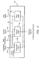
- system 10 is shown including an alternative flow meter 51, which includes a signal processor 52 configured to execute the flow logic 36 and diagnostic logic 38.
- Signal processor 51 receives the pressure signals P 1 (t), P 2 (t), P 3 (t), P 4 (t) and applies this data to the flow logic 36 executed by the signal processor 52.
- the flow logic 36 determines a parameter of the process flow, such as sound speed, mach number, consistency, composition, entrained air, density, mass flow rate, volumetric flow rate and others, in accordance with an algorithm.
- the signal processor 52 may then provide the determined flow parameter as a flow signal 24 to the signal processor 22, via electronic interface 20.
- the signal processor 52 may also apply one or more of the pressure signals P 1 (t), P 2 (t), P 3 (t), P 4 (t) and/or the flow signal 24 to diagnose the health of any device that causes unsteady pressures to be generated in the section of the pipe 14 where flow meter 51 is disposed.
- the diagnosed device may be any machinery, component, or equipment, e.g., motor, fan, pump, generator, engine, gearbox, belt, drive, pulley, hanger, clamp, actuator, valve, meter, or the like.
- the diagnostic logic 38 executed by the signal processor 52 may process one or more of the pressure signals P 1 (t), P 2 (t), P 3 (t), P 4 (t) and/or the flow signal 24 to diagnose the health of the device 12.
- the diagnostic logic 38 may compare the measured data to previously stored data or to input parameters 32, which is provided to the signal processor 52, via the operator interface 26, the signal processor 22, and the electronic interface 20, to diagnose or evaluate the changes between the measured and stored/input data.
- the signal processor 52 may output a diagnostic signal 28 indicative of the health of the diagnosed device to the signal processor 22 via electronic interface 20.
- the signal processor 52 uses less than all of the pressure signals P 1 (t), P 2 (t), P 3 (t), P 4 (t) to diagnose the health of a device, the signal processor 52 need not receive input from each pressure sensor 15-28. Indeed, it is contemplated that a single pressure sensor may be used to perform diagnostic monitoring, provided the sensor response bandwidth is sufficient to provide a pressure signal sufficient to compare and evaluate against the diagnostic evaluation criteria.
- the diagnostic signal 28 and the flow signal 24 are output in parallel to the electronic interface 20.
- these signals may be output in series (e.g., by multiplexing) along a common transmission path (e.g., wire).
- the signal processor 52 may include selection logic that determines whether the diagnostic signal 28 or the flow signal 24 is to be output from the signal processor 52. The selection logic may be responsive to a selection signal provided as part of the input parameters 32.
- the diagnostic signal 28 and the flow signal 24 may be output from the signal processor 22 to the operator interface 26 for monitoring by operating personnel.
- the signal processor 22 may apply the flow signal 24, and/or the diagnostic signal 28 to the control logic 40.
- the signal processor 22 provides the control signal 30 from the control logic 40 to at least one device 12 via the electronic interface 20 to change an operating parameter of at the least one device 12.
- the control logic 40 may, for example, compare the flow signal 24 to stored parameters, set points, or input parameters 32 to determine an appropriate control signal 30 for causing the appropriate operating condition of the one or more operating devices 12. For example, if fluid 13 flow is determined to be below a stored threshold value, control logic 40 may provide control signals 30 to valves and/or pumps in the flow process. In another example, if the diagnostic signal 28 indicates that a device is malfunctioning, then the control logic 40 may provide a control signal 30 effective to stop operation of the device.
- system 10 is shown including an alternative flow meter 61, which includes a signal processor 62 configured to execute the flow logic 36.
- the signal processor 62 receives the pressure signals P 1 (t), P 2 (t), P 3 (t), P 4 (t) and applies this data to the flow logic 36 executed by the signal processor 62.
- the flow logic 36 determines a parameter of the process flow, such as sound speed, mach number, consistency, composition, entrained air, density, mass flow rate, volumetric flow rate and others, in accordance with an algorithm.
- the signal processor 62 may then provide the determined flow parameter as a flow signal 24 to the signal processor 22, via electronic interface 20.
- the diagnostic logic 38 executed by the signal processor 22 may process the flow signal 24 to diagnose the health of the device 12 and provide a diagnostic signal 28 indicative of the health of the device.
- the diagnostic logic 38 may compare the measured data to previously stored data or to input parameters 32 to diagnose or evaluate the changes between the measured and stored or input data.
- the signal processor 22 may output the diagnostic signal 28 and the flow signal 24 to the operator interface 26.
- the signal processor 22 may apply the flow signal 24, and/or the diagnostic signal 28 to the control logic 40.
- the signal processor 22 provides the control signal 30 to at least one device 12 via the electronic interface 20 to change an operating parameter of at the least one device 12.
- the control logic 40 may, for example, compare the flow signal 24 to stored parameters, set points, or input parameters 32 to determine an appropriate control signal 30 for causing the appropriate operating condition of the one or more operating devices 12. For example, if fluid 13 flow is determined to be below a stored threshold value, control logic 40 may provide control signals 30 to valves and/or pumps in the flow process. In another example, if the diagnostic signal 28 indicates that a device is malfunctioning, then the control logic 40 may provide a control signal 30 effective to stop operation of the device.
- the electronic interface 20, signal processor 22, and operator interface 26 may be located remotely from the device 12 and any one or more of the flow meters 11, 51, and 61.
- any one or more of the flow meters 11, 51, and 61 may be located on a plant floor along with the device 12, and the electronic interface 20, signal processor 22, and operator interface 26 may be located at an isolated control station.
- the electronic interface 20 and signal processor 22 are located proximate to any one or more flow meters 11,51, and 61, with the operator interface being located remotely.
- the system 10 may monitor a plurality of flow meters comprising any combination of flow meters 11, 51 and 61. It is further contemplated that the system 10 may control a plurality of devices 12 in response to the signals received from the plurality of flow meters.
- the control system 10 may also monitor a plurality of standard meters 42, which may include consistency meters, density meters, standard flow meters, pressure sensors, temperature sensors, and the like, and control the plurality of devices 12 in response to signals received from these meters.
- the flow meters 11, 51, and 61, standard meters 42, and devices 12 separately communicate with the electronic interface 20; however, it is contemplated that all or a portion of the meters 11, 51, 61, and 42 may be connected to a common cable, with the signals from the connected meters 11, 51, 61, and 42 being multiplexed on the common cable using any known multiplexing technique.
- This multiplexed arrangement is similar to that found in the PlantWeb® architecture manufactured by Emerson Corporation.
- the flow meters 11, 51, and 61 each include the capability of providing multiplexed output in addition to the capability of providing parallel output. It is also contemplated that the flow meters 11, 51, and 61 each include the capability of communicating using various protocols and systems currently in use in the industrial sensing area.
- the flow meters 11, 51, and 61 may provide conventional 4-20 mA output signals formatted to the open protocol HART® (Highway Addressable Remote Transducer) digital communications format.
- communication from the flow meters 11, 51, and 61 may be performed with an open and interoperable protocol, such as FOUNDATIONTM Fieldbus that provides a digital communication link among intelligent field level and control devices via electrical lines.
- FOUNDATIONTM Fieldbus provides a digital communication link among intelligent field level and control devices via electrical lines.
- the flow meters 11 may be configured for use with other process protocols, including Device Bus, Sensor Bus, Profibus, Ethernet, and others.
- fiber optic based pressure sensors 15-18 makes the flow meters 11 particularly qualified for industrial applications requiring multiple sensors.
- the use of multiplexed flow meters 11 through the use of feedthroughs (or other known techniques) in a large multi-point process enables connectivity to the multiple flow meters 11 through a single fiber optic cable.
- Electronic sensors of the prior art require dedicated wiring to the electronic interface 20 and back to the sensor. For instance, a typical paper/pulp process control system that utilizes electronic flow meters of the prior art requires an electrical process loop to facilitate both a power signal to the transmitters and bi-directional communication.
- Fig. 6 shows the system 10 integrated in a pulp and paper application. Specifically, Fig. 6 illustrates a schematic diagram of a paper machine wet end including a plurality of flow meters 11, 51, and 61, other meters 42, and devices 12 as part of the system 10.
- system 10 embodying the present invention may function as a monitoring system to provide information to operating personnel. Further, the system 10 may include additional intelligence to process the input data from the flow meters 10 and diagnose problems or undesirable changes in the process flow. The system 10 may be further programmed to identify these changes or problems and provide a control signal 30 to various devices 12 to change the flow rate, composition or otherwise optimize the flow process. One will appreciate that the system 10 may also control the flow of the process in response to an input from the operating personnel via input from the operator interface 26.
- the pressure sensors 15-18 may be attached to the pipe by adhesive, glue, epoxy, tape or other suitable attachment means to ensure suitable contact between the sensor and the pipe 14.
- the pressure sensors 15-18 may alternatively be removable or permanently attached via known mechanical techniques such as mechanical fastener, spring loaded, clamped, clam shell arrangement, strapping or other equivalents.
- the pressure sensors 15-18 may be embedded in the pipe 14.
- the pressure sensors 15-18 may be selected from piezoelectric, piezoresistive, strain gauge, PVDF, optical sensors, ported ac pressure sensors, accelerometers, velocity sensors, and displacement sensors.
- any other strain sensing technique may be used to measure the variations in strain in the pipe 14, such as highly sensitive piezoelectric, electronic or electric, strain gages attached to or embedded in the pipe 14.
- a piezo-electronic pressure transducer may be used as one or more of the pressure sensors 15-18 and it may measure the unsteady (or dynamic or ac) pressure variations inside the pipe 14 by measuring the pressure levels inside of the pipe.
- the pressure sensors 15-18 comprise pressure sensors manufactured by PCB Piezotronics.
- Model 106B manufactured by PCB Piezotronics which is a high sensitivity, acceleration compensated integrated circuit piezoelectric quartz pressure sensor suitable for measuring low pressure acoustic phenomena in hydraulic and pneumatic systems. It has the unique capability to measure small pressure changes of less than 0.001 psi under high static conditions.
- the 106B has a 300 mV/psi sensitivity and a resolution of 91 dB (0.0001 psi).
- the pressure sensors 15-18 may incorporate a built-in MOSFET microelectronic amplifier to convert the high-impedance charge output into a low-impedance voltage signal.
- the pressure sensors 15-18 are powered from a constant-current source and can operate over long coaxial or ribbon cable without signal degradation.
- Power to operate integrated circuit piezoelectric sensors generally takes the form of a low-cost, 24 to 27 VDC, 2 to 20 mA constant-current supply.
- the system 10 of the present invention may incorporate constant-current power for directly powering integrated circuit piezoelectric pressure sensors 15-18.
- each of the pressure sensors 15-18 may include a piezoelectric material to measure the unsteady pressures of the fluid 13.
- the piezoelectric material such as the polymer, polarized fluoropolymer, polyvinylidene fluoride (PVDF), measures the strain induced within the process pipe 14 due to unsteady pressure variations within fluid 13. Strain within the pipe 14 is transduced to an output voltage or current by the attached piezoelectric pressure sensors 15-18.
- the PVDF material forming each of the pressure sensors 15-18 is adhered to the outer surface of a steel strap that extends around and clamps onto the outer surface of the pipe 14.
- the piezoelectric pressure sensors 15-18 are typically conformal to allow complete or nearly complete circumferential measurement of induced strain.
- the pressure sensors 15-18 can be formed from PVDF films, co-polymer films, or flexible PZT sensors, similar to that described in "Piezo Film Sensors technical Manual” provided by Measurement Specialties, Inc., which is incorporated herein by reference. The advantages of this technique are the following:
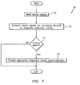
- the diagnostic logic 38 measures the sensor input signals (or evaluation input signals), which may include one or more of the pressure signals P 1 (t), P 2 (t), P 3 (t), P 4 (t) and the flow signal 24, at a step 70 ( Fig. 7 ).
- the diagnostic logic 38 compares the evaluation input signals to a diagnostic evaluation criteria at a step 72, discussed hereinafter. Then, a step 74 checks if there is a match, and if so, a step 76 provides a diagnostic signal 28 indicative of the diagnostic condition that has been detected and may also provide information identifying the diagnosed device. If there is not a criteria match in step 74, the diagnostic logic 38 exits.
- the diagnostic evaluation criteria may be based on a threshold value of the flow signal 24.
- the threshold value may be indicative of a maximum or minimum sound speed, mach number, consistency, composition, entrained air, density, mass flow rate, volumetric flow rate, or the like.
- the diagnostic evaluation criteria may be a threshold (maximum or minimum) pressure.
- the diagnostic evaluation criteria may be based on an acoustic signature, or a convective property (i.e., a property that propagates or convects with the flow).
- the diagnostic logic 38 may monitor the acoustic signature of any upstream or downstream device (e.g., motor, fan, pump, generator, engine, gear box, belt drive, pulley, hanger, clamp, actuator, valve, meter, or other machinery, equipment or component).
- the data from the array of sensors 15-18 may be processed in any domain, including the frequency/spatial domain, the temporal/spatial domain, the temporal/wave-number domain, or the wave-number/frequency (k- ⁇ ) domain or other domain, or any combination of one or more of the above.
- any known array processing technique in any of these or other related domains may be used if desired.
- Any technique known in the art for using a spatial (or phased) array of sensors to determine the acoustic or convective fields, beam forming, or other signal processing techniques, may be used to provide an input evaluation signal to be compared to the diagnostic evaluation criteria.
- each array of at least two sensors located at two locations x 1 ,x 2 axially along the pipe 14 sense respective stochastic signals propagating between the sensors within the pipe at their respective locations.
- Each sensor provides a signal indicating an unsteady pressure at the location of each sensor, at each instant in a series of sampling instants.
- each sensor array may include more than two sensors distributed at locations x 1... x N .
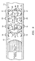
- the pressure generated by the convective pressure disturbances (e.g., eddies 120, see Fig. 9 ) may be measured through strained-based sensors and/or pressure sensors.
- the sensors provide analog pressure time-varying signals P 1 (t),P 2 (t),P 3 (t),P N (t) to the flow logic 36.
- the flow logic 36 processes the signals P 1 (t),P 2 (t),P 3 (t),P N (t) to first provide output signals (parameters) 21 indicative of the pressure disturbances that convect with the fluid (process flow) 13, and subsequently, provide output signals in response to pressure disturbances generated by convective waves propagating through the fluid 13, such as velocity, Mach number and volumetric flow rate of the process flow 13.
- the flow logic 36 processes the pressure signals to first provide output signals indicative of the pressure disturbances that convect with the process flow 13, and subsequently, provide output signals in response to pressure disturbances generated by convective waves propagating through the process flow 13, such as velocity, Mach number and volumetric flow rate of the process flow 13.
- the flow logic 36 receives the pressure signals from the array of sensors 15-18.
- a data acquisition unit 126 e.g., A/D converter
- the FFT logic 128 calculates the Fourier transform of the digitized time-based input signals P 1 (t) - P N (t) and provides complex frequency domain (or frequency based) signals P 1 ( ⁇ ),P 2 ( ⁇ ),P 3 ( ⁇ ),P N ( ⁇ ) indicative of the frequency content of the input signals.
- any other technique for obtaining the frequency domain characteristics of the signals P 1 (t) - P N (t) may be used.
- the cross-spectral density and the power spectral density may be used to form a frequency domain transfer functions (or frequency response or ratios) discussed hereinafter.
- One technique of determining the convection velocity of the turbulent eddies 120 within the process flow 13 is by characterizing a convective ridge of the resulting unsteady pressures using an array of sensors or other beam forming techniques, similar to that described in U.S Patent Application, Serial No. (Cidra's Docket No. CC-0122A) and U.S. Patent Application, Serial No. 09/729,994 (Cidra's Docket No. CC-0297), filed December 4, 200, now US6,609,069 , which are incorporated herein by reference.
- a data accumulator 130 accumulates the frequency signals P l ( ⁇ ) - P N ( ⁇ ) over a sampling interval, and provides the data to an array processor 132, which performs a spatial-temporal (two-dimensional) transform of the sensor data, from the xt domain to the k- ⁇ domain, and then calculates the power in the k- ⁇ plane, as represented by a k- ⁇ plot.
- the array processor 132 uses standard so-called beam forming, array processing, or adaptive array-processing algorithms, i.e. algorithms for processing the sensor signals using various delays and weighting to create suitable phase relationships between the signals provided by the different sensors, thereby creating phased antenna array functionality.
- the prior art teaches many algorithms of use in spatially and temporally decomposing a signal from a phased array of sensors, and the present invention is not restricted to any particular algorithm.
- One particular adaptive array processing algorithm is the Capon method/algorithm. While the Capon method is described as one method, the present invention contemplates the use of other adaptive array processing algorithms, such as MUSIC algorithm.
- the present invention recognizes that such techniques can be used to determine flow rate, i.e. that the signals caused by a stochastic parameter convecting with a flow are time stationary and have a coherence length long enough that it is practical to locate sensor units apart from each other and yet still be within the coherence length.
- k ⁇ / u
- u the convection velocity (flow velocity).
- a plot of k- ⁇ pairs obtained from a spectral analysis of sensor samples associated with convective parameters portrayed so that the energy of the disturbance spectrally corresponding to pairings that might be described as a substantially straight ridge, a ridge that in turbulent boundary layer theory is called a convective ridge.
- What is being sensed are not discrete events of turbulent eddies, but rather a continuum of possibly overlapping events forming a temporally stationary, essentially white process over the frequency range of interest.
- the convective eddies 120 is distributed over a range of length scales and hence temporal frequencies.
- the array processor 132 determines the wavelength and so the (spatial) wavenumber k, and also the (temporal) frequency and so the angular frequency ⁇ , of various of the spectral components of the stochastic parameter.
- the array processor 132 determines the wavelength and so the (spatial) wavenumber k, and also the (temporal) frequency and so the angular frequency ⁇ , of various of the spectral components of the stochastic parameter.
- the present invention may use temporal and spatial filtering to precondition the signals to effectively filter out the common mode characteristics P common mode and other long wavelength (compared to the sensor spacing) characteristics in the pipe 14 by differencing adjacent sensors and retain a substantial portion of the stochastic parameter associated with the flow field and any other short wavelength (compared to the sensor spacing) low frequency stochastic parameters.
- the power in the k- ⁇ plane shown in a k- ⁇ plot of Fig. 10 shows a convective ridge 124.
- the convective ridge represents the concentration of a stochastic parameter that convects with the flow and is a mathematical manifestation of the relationship between the spatial variations and temporal variations described above.
- Such a plot will indicate a tendency for k- ⁇ pairs to appear more or less along a line 124 with some slope, the slope indicating the flow velocity.
- a convective ridge identifier 134 uses one or another feature extraction method to determine the location and orientation (slope) of any convective ridge 124 present in the k- ⁇ plane.
- a so-called slant stacking method is used, a method in which the accumulated frequency of k- ⁇ pairs in the k- ⁇ plot along different rays emanating from the origin are compared, each different ray being associated with a different trial convection velocity (in that the slope of a ray is assumed to be the flow velocity or correlated to the flow velocity in a known way).
- the convective ridge identifier 134 provides information about the different trial convection velocities, information referred to generally as convective ridge information.
- Some or all of the functions within the flow logic 36 may be implemented in software (using a microprocessor or computer) and/or firmware, or may be implemented using analog and/or digital hardware, having sufficient memory, interfaces, and capacity to perform the functions described herein.
- FIG. 11 another example of flow logic 36 is shown. While the examples of Fig. 11 and Fig. 12 are shown separately, it is contemplated that the flow logic 36 may perform all of the functions described with reference to Fig. 11 and Fig. 12 .
- the array of at least two sensors located at two at least two locations x 1 ,x 2 axially along the pipe 14 sense respective stochastic signals propagating between the sensors within the pipe at their respective locations. Each sensor provides a signal indicating an unsteady pressure at the location of each sensor, at each instant in a series of sampling instants.
- the sensor array may include more than two pressure sensors distributed at locations x 1 ...x N .
- the pressure generated by the acoustic pressure disturbances may be measured through strained-based sensors and/or pressure sensors.
- the sensors provide analog pressure time-varying signals P 1 (t),P 2 (t),P 3 (t),P N (t) to the flow logic 36.
- the flow logic 36 processes the signals P 1 (t),P 2 (t),P 3 (t),P N (t) to first provide output signals indicative of the speed of sound propagating through the fluid (process flow) 13, and subsequently, provide output signals in response to pressure disturbances generated by acoustic waves propagating through the process flow 13, such as velocity, Mach number and volumetric flow rate of the process flow 13.
- the flow logic 36 receives the pressure signals from the array of sensors 15-18.
- a data acquisition unit 138 digitizes pressure signals P 1 (t)-P N (t) associated with the acoustic waves 122 propagating through the pipe 14.
- an FFT logic 140 calculates the Fourier transform of the digitized time-based input signals P 1 (t) - P N (t) and provide complex frequency domain (or frequency based) signals P 1 ( ⁇ ),P 2 ( ⁇ ),P 3 ( ⁇ ),P N ( ⁇ ) indicative of the frequency content of the input signals.
- a data accumulator 142 accumulates the frequency signals P 1 ( ⁇ ) - P N ( ⁇ ) over a sampling interval, and provides the data to an array processor 144, which performs a spatial-temporal (two-dimensional) transform of the sensor data, from the xt domain to the k- ⁇ domain, and then calculates the power in the k- ⁇ plane, as represented by a k- ⁇ plot.
- the array processor 144 determines the wavelength and so the (spatial) wavenumber k, and also the (temporal) frequency and so the angular frequency ⁇ , of various of the spectral components of the stochastic parameter.
- the array processor 144 determines the wavelength and so the (spatial) wavenumber k, and also the (temporal) frequency and so the angular frequency ⁇ , of various of the spectral components of the stochastic parameter.
- the power in the k- ⁇ plane shown in a k- ⁇ plot of Fig. 12 so determined will exhibit a structure that is called an acoustic ridge 150, 152 in both the left and right planes of the plot, wherein one of the acoustic ridges 150 is indicative of the speed of sound traveling in one axial direction and the other acoustic ridge 152 being indicative of the speed of sound traveling in the other axial direction.
- the acoustic ridges represent the concentration of a stochastic parameter that propagates through the flow and is a mathematical manifestation of the relationship between the spatial variations and temporal variations described above. Such a plot will indicate a tendency for k- ⁇ pairs to appear more or less along a line 150, 152 with some slope, the slope indicating the speed of sound.
- the power in the k- ⁇ plane so determined is then provided to an acoustic ridge identifier 146, which uses one or another feature extraction method to determine the location and orientation (slope) of any acoustic ridge present in the left and right k- ⁇ plane.
- the velocity may be determined by using the slope of one of the two acoustic ridges 150, 152 or averaging the slopes of the acoustic ridges 150, 152.
- information including the acoustic ridge orientation (slope) is used by an analyzer 148 to determine the flow parameters relating to measured speed of sound, such as the consistency or composition of the flow, the density of the flow, the average size of particles in the flow, the air/mass ratio of the flow, gas volume fraction of the flow, the speed of sound propagating through the flow, and/or the percentage of entrained air within the flow.
- the flow parameters relating to measured speed of sound such as the consistency or composition of the flow, the density of the flow, the average size of particles in the flow, the air/mass ratio of the flow, gas volume fraction of the flow, the speed of sound propagating through the flow, and/or the percentage of entrained air within the flow.
- the array processor 144 uses standard so-called beam forming, array processing, or adaptive array-processing algorithms, i.e. algorithms for processing the sensor signals using various delays and weighting to create suitable phase relationships between the signals provided by the different sensors, thereby creating phased antenna array functionality.
- One such technique of determining the speed of sound propagating through the process flow 13 is using array processing techniques to define an acoustic ridge in the k- ⁇ plane as shown in Fig. 12 .
- the slope of the acoustic ridge is indicative of the speed of sound propagating through the process flow 13.
- the speed of sound (SOS) is determined by applying sonar arraying processing techniques to determine the speed at which the one dimensional acoustic waves propagate past the axial array of unsteady pressure measurements distributed along the pipe 14.
- the flow logic 36 of the present embodiment measures the speed of sound (SOS) of one-dimensional sound waves propagating through the process flow 13 to determine the gas volume fraction of the process flow 13. It is known that sound propagates through various mediums at various speeds in such fields as SONAR and RADAR fields.
- the speed of sound propagating through the pipe 14 and process flow 13 may be determined using a number of known techniques, such as those set forth in U.S. Patent Application Serial No. 09/344,094, filed June 25, 1999 , now US 6,354,147 ; U.S. Patent Application Serial No. 10/795,111, filed March 4, 2004 ; U.S. Patent Application Serial No. 09/997,221, filed November 28, 2001 , now US 6,587,798 ; U.S. Patent Application Serial No. 10/007,749, filed November 7, 2001 , and U.S. Patent Application Serial No. 10/762,410, filed January 21, 2004 , each of which are incorporated herein by reference.
- sonar-based flow meter using an array of sensors 15-18 to measure the speed of sound of an acoustic wave propagating through the mixture is shown and described, one will appreciate that any means for measuring the speed of sound of the acoustic wave may used to determine the entrained gas volume fraction of the mixture/fluid or other characteristics of the flow described hereinbefore.
- the analyzer 148 of the flow logic 36 provides output parameters 21 indicative of characteristics of the process flow 13 that are related to the measured speed of sound (SOS) propagating through the process flow 13. For example, to determine the gas volume fraction (or phase fraction), the analyzer 148 assumes a nearly isothermal condition for the process flow 13.
- SOS measured speed of sound
- the sound speed of a mixture can be related to volumetric phase fraction ( ⁇ i ) of the components and the sound speed (a) and densities (p) of the component through the Wood equation.
- One dimensional compression waves propagating within a process flow 13 contained within a pipe 14 exert an unsteady internal pressure loading on the pipe.
- the degree to which the pipe displaces as a result of the unsteady pressure loading influences the speed of propagation of the compression wave.
- the mixing rule essentially states that the compressibility of a process flow (1/( ⁇ a 2 )) is the volumetrically-weighted average of the compressibilities of the components.
- a process flow 13 consisting of a gas/liquid mixture at pressure and temperatures typical of paper and pulp industry
- the compressibility of gas phase is orders of magnitudes greater than that of the liquid.
- the compressibility of the gas phase and the density of the liquid phase primarily determine mixture sound speed, and as such, it is necessary to have a good estimate of process pressure to interpret mixture sound speed in terms of volumetric fraction of entrained gas.
- the effect of process pressure on the relationship between sound speed and entrained air volume fraction is shown in Fig. 13 .
- the flow logic 36 of the present embodiment includes the ability to accurately determine the average particle size of a particle/air or droplet/air mixture within the pipe 14 and the air to particle ratio.
- the propagation of one dimensional sound wave through multiphase mixtures is influenced by the effective mass and the effective compressibility of the mixture.
- the degree to which the no-slip assumption applies is a strong function of particle size and frequency. In the limit of small particles and low frequency, the no-slip assumption is valid. As the size of the particles increases and the frequency of the sound waves increase, the non-slip assumption becomes increasing less valid.
- the increase in slip with frequency causes dispersion, or, in other words, the sound speed of the mixture to change with frequency.
- dispersive characteristic of a process flow 13 will provide a measurement of the average particle size, as well as, the air to particle ratio (particle/fluid ratio) of the process flow 13.
- the dispersive nature of the system utilizes a first principles model of the interaction between the air and particles.
- This model is viewed as being representative of a class of models that seek to account for dispersive effects.
- Other models could be used to account for dispersive effects without altering the intent of this disclosure (for example, see the paper titled "Viscous Attenuation of Acoustic Waves in Suspensions" by R.L. Gibson, Jr. and M.N. Toksöz), which is incorporated herein by reference.
- the model allows for slip between the local velocity of the continuous fluid phase and that of the particles.
- a mix ⁇ a f 1 1 + ⁇ p ⁇ p ⁇ f 1 + ⁇ 2 ⁇ p 2 v p 2 K 2
- the fluid SOS, density ( ⁇ ) and viscosity ( ⁇ ) are those of the pure phase fluid
- v p is the volume of individual particles
- ⁇ p is the volumetric phase fraction of the particles in the mixture.
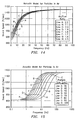
- Fig. 14 and Fig. 15 show the dispersive behavior in relations to the speed of sound for coal/air mixtures with parameters typical of those used in pulverized coal deliver systems.
- Fig. 14 shows the predicted behavior for nominally 50 ⁇ m size coal in air for a range of air-to-fuel ratios.
- the effect of air-to-fuel ratio is well defined in the low frequency limit.
- the effect of the air-to-fuel ratio becomes indistinguishable at higher frequencies, approaching the sound speed of the pure air at high frequencies (above ⁇ 100 Hz).
- Fig. 9 shows the predicted behavior for a coal/air mixture with an air-to-fuel ratio of 1.8 with varying particle size. This figure illustrates that particle size has no influence on either the low frequency limit (quasi-steady) sound speed, or on the high frequency limit of the sound speed. However, particle size does have a pronounced effect in the transition region.
- Fig. 14 and Fig. 15 illustrate an important aspect of the present invention. Namely, that the dispersive properties of dilute mixtures of particles suspended in a continuous liquid can be broadly classified into three frequency regimes: low frequency range, high frequency range and a transitional frequency range. Although the effect of particle size and air-to-fuel ratio are inter-related, the predominant effect of air-to-fuel ratio is to determine the low frequency limit of the sound speed to be measured and the predominate effect of particle size is to determine the frequency range of the transitional regions. As particle size increases, the frequency at which the dispersive properties appear decreases. For typical pulverized coal applications, this transitional region begins at fairly low frequencies, ⁇ 2Hz for 50 ⁇ m size particles.
- Some or all of the functions within the flow logic 36 may be implemented in software (using a microprocessor or computer) and/or firmware, or may be implemented using analog and/or digital hardware, having sufficient memory, interfaces, and capacity to perform the functions described herein.
- Fig. 8 and Fig. 11 depict two different embodiments of the flow logic 36 to measure various parameters of the flow process, the present invention contemplates that the functions of these two embodiments may be performed by a single flow logic 36.
Landscapes
- Physics & Mathematics (AREA)
- Fluid Mechanics (AREA)
- General Physics & Mathematics (AREA)
- Acoustics & Sound (AREA)
- Electromagnetism (AREA)
- Measuring Volume Flow (AREA)
- Arrangements For Transmission Of Measured Signals (AREA)
- Testing And Monitoring For Control Systems (AREA)
- Flow Control (AREA)
Claims (28)
- System (10) zum Überwachen der Gesundheit einer Vorrichtung (12), die mit einem Rohr (14) akustisch gekoppelt ist, wobei die Vorrichtung (12) die Erzeugung von schwankenden Drücken in einem in dem Rohr (14) strömenden Fluid verursacht, wobei das System (10) Folgendes aufweist:eine Anordnung von Drucksensoren (15, 16, 17, 18), die entlang des Rohrs (14) angeordnet sind, um schwankende Drücke im Inneren des Rohrs (14) zu messen, wobei jeder der Sensoren ein Drucksignal (P1(t), P2(t), P3(t), P4(t)) bereitstellt; undeinen Signalprozessor (22), der dazu ausgebildet ist, die von den Drucksensoren (15, 16, 17, 18) bereitgestellten Drucksignale (P1(t), P2(t), P3(t), P4(t)) zu empfangen;dadurch gekennzeichnet, dass die Anordnung von Drucksensoren (15, 16, 17, 18) entlang des Rohrs (14) stromabwärts von der Vorrichtung (12) angeordnet ist und dass der Signalprozessor (22) ferner dazu ausgebildet ist:eine Ablauflogik (36) an den Drucksignalen (P1(t), P2(t), P3(t), P4(t)) anzuwenden, um einen Parameter des Fluids (13) zu bestimmen;den bestimmten Parameter des Fluids (13) als Strömungssignal (24) bereitzustellen, undeines oder mehrere der Drucksignale (P1(t), P2(t), P3(t), P4(t)) zum Diagnostizieren der Gesundheit der Vorrichtung (12) anzuwenden und ein Diagnose-Ausgangssignal bereitzustellen, das die Gesundheit der Vorrichtung (12) anzeigt;wobei der Parameter des Fluids (13) zumindest die Geschwindigkeit des Schalls in dem Fluid (13) beinhaltet und der Signalprozessor (12) eine Ablauflogik beinhaltet, die zum Bestimmen einer Steigung eines akustischen Grats in einer k-ω-Ebene konfiguriert ist, um die Geschwindigkeit des sich durch das Fluid (13) ausbreitenden Schalls zu bestimmen.
- System (10) nach Anspruch 1,
wobei die Vorrichtung (12) zumindest an der Position des mindestens einen Sensors (15, 16, 17, 18) mit dem Rohr (14) akustisch gekoppelt ist. - System (10) nach Anspruch 1 oder 2,
wobei der mindestens eine Sensor (15, 16, 17, 18) eine axiale Anordnung von mindestens zwei Sensoren (15, 16, 17, 18) aufweist. - System (10) nach einem der Ansprüche 1 bis 3,
wobei der mindestens eine Sensor (15, 16, 17, 18) aus einer Gruppe ausgewählt ist, bestehend aus: piezoelektrischen Sensoren, Piezowiderstands-Sensoren, Dehnungsmessungs-Sensoren, PVDF-Sensoren, optischen Sensoren, mit Anschlüssen versehenen Wechselstrom-Drucksensoren, Beschleunigungsmessern, Geschwindigkeitssensoren und Verschiebungssensoren. - System (10) nach einem der Ansprüche 1 bis 4,
wobei die Vorrichtung (12) mindestens eines von Elektromotoren, Gebläsen, Pumpen, Generatoren, Verbrennungsmotoren, Getrieben, Riemen, Antrieben, Riemenscheiben, Aufhängungseinrichtungen, Klammern, Aktuatoren, Ventilen, Wärmetauschern und Messeinrichtungen beinhaltet. - System (10) nach einem der vorhergehenden Ansprüche,
das ferner eine Strömungsverarbeitungslogik (22) aufweist, die auf die Sensoreingangssignale anspricht, so dass ein Strömungsmessungs-Ausgangssignal bereitgestellt wird, das mindestens einen Strömungsparameter eines im Inneren des Rohrs (14) fließenden Materials anzeigt. - System (10) nach Anspruch 6,
das ferner eine Auswahllogik aufweist, die auf das Diagnose-Ausgangssignal und das Strömungsmessungs-Ausgangssignal anspricht, so dass ein Überwachungs-Ausgangssignal bereitgestellt wird, das zumindest ein Strömungsmessungs-Ausgangssignal und Diagnose-Ausgangssignal anzeigt. - System (10) nach einem der vorhergehenden Ansprüche,
wobei die Diagnoseverarbeitungslogik (22) eine Logik aufweist, die ein auf den Sensoreingangssignalen basierendes Eingangsauswertungssignal gegenüber Diagnose-Auswertungskriterien vergleicht, um den Diagnosezustand der Vorrichtung (12) zu bestimmen. - System (10) nach Anspruch 8,
wobei die Auswertungskriterien auf einer Signatur in mindestens einem von dem Frequenzbereich, dem Zeitbereich, dem räumlichen Bereich, der Wellenanzahl und dem k-ω-Bereich basieren. - System (10) nach einem der vorhergehenden Ansprüche,
wobei der mindestens eine Sensor (15, 16, 17, 18) eine Messeinrichtung zum Messen von mindestens einem Parameter eines Fluids (13) in dem Strömungsprozess aufweist, wobei die Messeinrichtung eine räumliche Anordnung von mindestens zwei Sensoren (15, 16, 17, 18) aufweist, die an unterschiedlichen axialen Stellen entlang eines Rohrs (14) in dem Strömungsprozess angeordnet sind, wobei jeder der mindestens zwei Sensoren (15, 16, 17, 18) ein Drucksignal bereitstellt, das einen schwankenden Druck innerhalb des Rohrs (14) an einer entsprechenden axialen Stelle anzeigt; und
wobei die Diagnoseverarbeitungslogik (22) einen Signalprozessor aufweist, der zum Abgeben von mindestens einem von einem Strömungssignal, einem Diagnosesignal und einem Steuersignal in Reaktion auf die Drucksignale ausgebildet ist, wobei das Strömungssignal den mindestens einen Parameter des Fluids (13) anzeigt, das Diagnosesignal einen Diagnosezustand einer Vorrichtung (12) in dem Strömungsprozess anzeigt und das Steuersignal beim Einstellen eines Betriebsparameters von mindestens einer Vorrichtung (12) in dem Strömungsprozess wirksam ist. - System (10) nach Anspruch 10,
das ferner eine Auswahllogik aufweist, die auf das Diagnosesignal und das Strömungssignal anspricht, wobei die Auswahllogik ein Überwachungs-Ausgangssignal bereitstellt, das mindestens eines von dem Strömungssignal und dem Diagnosesignal anzeigt. - System (10) nach Anspruch 1,
wobei es sich bei dem Parameter des Fluids (13) um den Gasvolumenanteil des Fluids (13) handelt, und wobei es sich bei dem Fluid (13) um eines von einer Flüssigkeit mit mitgeführtem Gas, einer Mischung mit mitgeführtem Gas und einer Aufschlämmung mit mitgeführtem Gas handelt. - System (10) nach Anspruch 12,
wobei der Signalprozessor eine Ablauflogik aufweist, die zum Bestimmen des Gasvolumenanteils der Strömung in Reaktion auf die gemessene Geschwindigkeit des Schalls ausgebildet ist. - System (10) nach Anspruch 13,
wobei die Ablauflogik ferner dazu ausgebildet ist: die volumetrische Strömungsrate durch das Rohr (14) unter Verwendung einer Querschnittsfläche des Rohrs (14) und der Geschwindigkeit des Fluids (13) zu berechnen sowie die volumetrische Strömungsrate des Fluids (13) unter Verwendung des Gasvolumenanteils des Fluids (13) zu korrigieren. - System (10) nach einem der Ansprüche 10 bis 14,
wobei die mindestens zwei Drucksensoren (15, 16, 17, 18) aus einer Gruppe ausgewählt sind, die aus piezoelektrischen Sensoren, Piezowiderstands-Sensoren, Dehnungsmessungs-Sensoren, PVDF-Sensoren, optischen Sensoren, mit Anschlüssen versehenen Wechselstrom-Drucksensoren, Beschleunigungsmessern, Geschwindigkeitssensoren und Verschiebungssensoren besteht. - System (10) nach einem der Ansprüche 10 bis 15,
wobei die mindestens zwei Drucksensoren (15, 16, 17, 18) zumindest um einen Teil des Rohrs (14) herum platziert sind und das Fluid (13) nicht berühren. - System (10) nach einem der Ansprüche 10 bis 16,
wobei der Signalprozessor ein auf den Drucksignalen basierendes Eingangsauswertungssignal gegenüber Diagnose-Auswertungskriterien vergleicht, um den Diagnosezustand der Vorrichtung (12) zu bestimmen. - System (10) nach Anspruch 17,
wobei die Auswertungskriterien auf einer Signatur in mindestens einem von dem Frequenzbereich, dem Zeitbereich, dem räumlichen Bereich, der Wellenanzahl und dem k-ω -Bereich basieren. - Verfahren zum Überwachen der Gesundheit einer Vorrichtung (12), die mit einem Rohr (14) akustisch gekoppelt ist, wobei die Vorrichtung (12) die Erzeugung von schwankenden Drücken in einem in dem Rohr (14) strömenden Fluid verursacht, wobei das Verfahren folgende Schritte aufweist:Anordnen einer Anordnung von Drucksensoren (15, 16, 17, 18) zum Messen von Drücken im Inneren des Rohrs (14) entlang eines Abschnitts des Rohrs (14), in dem die schwankenden Drücke in dem Fluid (13) vorhanden sind, wobei jeder der Sensoren ein Drucksignal (P1(t), P2(t), P3(t), P4(t)) bereitstellt;dadurch gekennzeichnet, dass die Anordnung von Drucksensoren (15, 16, 17, 18) entlang des Rohrs (14) stromabwärts von der Vorrichtung (12) angeordnet wird und dass das Verfahren ferner aufweist:Anwenden einer Ablauflogik (36) an den Drucksignalen (P1(t), P2(t), P3(t), P4(t)), um einen Parameter des Fluids (13) zu bestimmen;Bereitstellen des bestimmten Parameters des Fluids (13) als Strömungssignal (24), undAnwenden von einem oder mehreren der Drucksignale (P1(t), P2(t), P3(t), P4(t)) zum Diagnostizieren der Gesundheit der Vorrichtung (12); undBereitstellen eines Diagnosezustands, der die Gesundheit der Vorrichtung (12) anzeigt;wobei der Parameter des Fluids (13) zumindest die Geschwindigkeit des Schalls in dem Fluid (13) beinhaltet und das Verfahren das Bestimmen einer Steigung eines akustischen Grats in einer k-w-Ebene beinhaltet, um die Geschwindigkeit des sich durch das Fluid (13) ausbreitenden Schalls zu bestimmen.
- Verfahren nach Anspruch 19,
wobei das Bereitstellen des Diagnosesignals beinhaltet:Vergleichen eines auf den Drucksignalen basierenden Eingangsauswertungssignals gegenüber Diagnose-Auswertungskriterien zum Bestimmen des Diagnosezustands der Vorrichtung (12). - Verfahren nach Anspruch 20,
wobei die Auswertungskriterien auf einer Signatur in mindestens einem von dem Frequenzbereich, dem Zeitbereich, dem räumlichen Bereich, der Wellenanzahl und dem k-ω-Bereich basieren. - Verfahren zum Betreiben eines Strömungsprozesses, wobei das Verfahren das Überwachen der Gesundheit einer Vorrichtung (12) nach einem der Ansprüche 20 bis 22 beinhaltet und ferner folgende Schritte aufweist:Empfangen von Drucksignalen von einer Messeinrichtung mit einer räumlichen Anordnung von mindestens zwei Drucksensoren (15, 16, 17, 18), die an verschiedenen axialen Stellen entlang eines Rohrs (14) in dem Strömungsprozess angeordnet sind, wobei jeder der mindestens zwei Drucksensoren (15, 16, 17, 18) ein Drucksignal bereitstellt, das einen schwankenden Druck im Inneren des Rohrs (14) an einer entsprechen axialen Stelle anzeigt; undBereitstellen von mindestens einem von einem Diagnosesignal und einem Strömungssignal in Reaktion auf die Drucksignale, wobei das Diagnosesignal einen Diagnosezustand einer Vorrichtung (12) des Strömungsprozesses anzeigt und das Strömungssignal einen Parameter eines in dem Strömungsprozess strömenden Fluids anzeigt.
- Verfahren nach Anspruch 22,
wobei es sich bei dem Parameter des Fluids (13) um den Gasvolumenanteil des Fluids (13) handelt, und wobei es sich bei dem Fluid (13) um eines von einer Flüssigkeit mit mitgeführtem Gas, einer Mischung mit mitgeführtem Gas und einer Aufschlämmung mit mitgeführtem Gas handelt. - Verfahren nach einem der Ansprüche 22 oder 23,
wobei die Verarbeitung der Drucksignale zum Bereitstellen des Strömungssignals das Bestimmen des Gasvolumenanteils der Strömung in Reaktion auf die gemessene Geschwindigkeit des Schalls beinhaltet. - Verfahren nach einem der Ansprüche 22 bis 24,
wobei das Verarbeiten der Drucksignale zum Bereitstellen des Strömungssignals ferner beinhaltet: Bestimmen der volumetrischen Strömungsrate des Rohrs (14) unter Verwendung einer Querschnittsfläche des Rohrs (14) und der Geschwindigkeit des Fluids (13), sowie Korrigieren der volumentrischen Strömungsrate des Fluids (13) unter Verwendung des Gasvolumenanteilsdes Fluids (13) - Verfahren nach einem der Ansprüche 22 bis 25,
wobei die Vorrichtung (12) zumindest an der Stelle der räumlichen Anordnung mit dem Rohr (14) akustisch gekoppelt wird. - Verfahren nach einem der Ansprüche 22 bis 26,
wobei die mindestens zwei Drucksensoren (15, 16, 17, 18) aus einer Gruppe ausgewählt werden, die aus piezoelektrischen Sensoren, Piezowiderstands-Sensoren, Dehnungsmessungs-Sensoren, PVDF-Sensoren, optischen Sensoren, mit Anschlüssen versehenen Wechselstrom-Drucksensoren, Beschleunigungsmessern, Geschwindigkeitssensoren und Verschiebungssensoren besteht. - Verfahren nach einem der Ansprüche 22 bis 27,
wobei die mindestens zwei Drucksensoren (15, 16, 17, 18) zumindest um einen Teil des Rohrs (14) herum platziert werden und Fluid (13) innerhalb des Strömungsprozesses nicht berühren.
Applications Claiming Priority (4)
| Application Number | Priority Date | Filing Date | Title |
|---|---|---|---|
| US48226403P | 2003-06-24 | 2003-06-24 | |
| US48767803P | 2003-07-15 | 2003-07-15 | |
| US48776503P | 2003-07-15 | 2003-07-15 | |
| PCT/US2004/020262 WO2005001586A2 (en) | 2003-06-24 | 2004-06-24 | System and method for operating a flow process |
Publications (2)
| Publication Number | Publication Date |
|---|---|
| EP1644705A2 EP1644705A2 (de) | 2006-04-12 |
| EP1644705B1 true EP1644705B1 (de) | 2016-10-12 |
Family
ID=33556424
Family Applications (1)
| Application Number | Title | Priority Date | Filing Date |
|---|---|---|---|
| EP04777027.6A Expired - Lifetime EP1644705B1 (de) | 2003-06-24 | 2004-06-24 | System und verfahren zum betreiben eines flussprozesses |
Country Status (4)
| Country | Link |
|---|---|
| US (2) | US7623976B2 (de) |
| EP (1) | EP1644705B1 (de) |
| CA (2) | CA2530596C (de) |
| WO (2) | WO2005003693A2 (de) |
Families Citing this family (63)
| Publication number | Priority date | Publication date | Assignee | Title |
|---|---|---|---|---|
| US7165464B2 (en) * | 2002-11-15 | 2007-01-23 | Cidra Corporation | Apparatus and method for providing a flow measurement compensated for entrained gas |
| CA2513248C (en) * | 2003-01-13 | 2013-01-08 | Cidra Corporation | Apparatus and method using an array of ultrasonic sensors for determining the velocity of a fluid within a pipe |
| US20060048583A1 (en) * | 2004-08-16 | 2006-03-09 | Gysling Daniel L | Total gas meter using speed of sound and velocity measurements |
| WO2004065912A2 (en) * | 2003-01-21 | 2004-08-05 | Cidra Corporation | Apparatus and method for measuring unsteady pressures within a large diameter pipe |
| US7623976B2 (en) * | 2003-06-24 | 2009-11-24 | Cidra Corporate Services, Inc. | System of distributed configurable flowmeters |
| WO2005003695A1 (en) * | 2003-06-24 | 2005-01-13 | Cidra Corporation | Characterizing unsteady pressures in pipes using optical measurement devices |
| WO2005054789A1 (en) * | 2003-07-08 | 2005-06-16 | Cidra Corporation | Method and apparatus for measuring characteristics of core-annular flow |
| WO2005010468A2 (en) * | 2003-07-15 | 2005-02-03 | Cidra Corporation | A configurable multi-function flow measurement apparatus having an array of sensors |
| WO2005010469A2 (en) | 2003-07-15 | 2005-02-03 | Cidra Corporation | A dual function flow measurement apparatus having an array of sensors |
| US7882750B2 (en) * | 2003-08-01 | 2011-02-08 | Cidra Corporate Services, Inc. | Method and apparatus for measuring parameters of a fluid flowing within a pipe using a configurable array of sensors |
| CA2537800C (en) * | 2003-08-08 | 2013-02-19 | Cidra Corporation | Piezocable based sensor for measuring unsteady pressures inside a pipe |
| US7117048B2 (en) * | 2003-09-30 | 2006-10-03 | Rockwell Automation Technologies, Inc. | Safety controller with safety response time monitoring |
| US7237440B2 (en) * | 2003-10-10 | 2007-07-03 | Cidra Corporation | Flow measurement apparatus having strain-based sensors and ultrasonic sensors |
| BRPI0508637B1 (pt) * | 2004-03-10 | 2017-10-10 | Cidra Corporation | Method and apparatus for measuring parameters of a stratified flow |
| US7367239B2 (en) | 2004-03-23 | 2008-05-06 | Cidra Corporation | Piezocable based sensor for measuring unsteady pressures inside a pipe |
| US7426852B1 (en) | 2004-04-26 | 2008-09-23 | Expro Meters, Inc. | Submersible meter for measuring a parameter of gas hold-up of a fluid |
| WO2005116637A2 (en) * | 2004-05-17 | 2005-12-08 | Cidra Corporation | Apparatus and method for measuring the composition of a mixture |
| WO2006112878A2 (en) | 2004-09-16 | 2006-10-26 | Cidra Corporation | Apparatus and method for providing a fluid cut measurement of a multi-liquid mixture compensated for entrained gas |
| US7389687B2 (en) * | 2004-11-05 | 2008-06-24 | Cidra Corporation | System for measuring a parameter of an aerated multi-phase mixture flowing in a pipe |
| US8017858B2 (en) * | 2004-12-30 | 2011-09-13 | Steve Mann | Acoustic, hyperacoustic, or electrically amplified hydraulophones or multimedia interfaces |
| US7962293B2 (en) * | 2005-03-10 | 2011-06-14 | Expro Meters, Inc. | Apparatus and method for providing a stratification metric of a multiphase fluid flowing within a pipe |
| US7725270B2 (en) | 2005-03-10 | 2010-05-25 | Expro Meters, Inc. | Industrial flow meter having an accessible digital interface |
| DE102005023115B4 (de) * | 2005-05-19 | 2010-03-11 | Technische Universität Darmstadt | Verfahren zum Überwachen einer Fluid-Durchflußmessung und Sensorsystem für eine Fluid-Durchflußmessung |
| WO2006130499A2 (en) * | 2005-05-27 | 2006-12-07 | Cidra Corporation | An apparatus and method for fiscal measuring of an aerated fluid |
| US7526966B2 (en) * | 2005-05-27 | 2009-05-05 | Expro Meters, Inc. | Apparatus and method for measuring a parameter of a multiphase flow |
| EP1899686B1 (de) * | 2005-07-07 | 2011-09-28 | CiDra Corporation | Feuchtgasmessung unter verwendung eines differentialdruckbasierten durchflussmeters mit einem sonarbasierten durchflussmeter |
| US7503227B2 (en) * | 2005-07-13 | 2009-03-17 | Cidra Corporate Services, Inc | Method and apparatus for measuring parameters of a fluid flow using an array of sensors |
| US7814936B2 (en) * | 2005-11-16 | 2010-10-19 | Fisher Controls International Llc | Sound pressure level feedback control |
| US8027793B2 (en) * | 2006-07-10 | 2011-09-27 | Daniel Measurement And Control, Inc. | Method and system of validating data regarding measured hydrocarbon flow |
| US7624650B2 (en) | 2006-07-27 | 2009-12-01 | Expro Meters, Inc. | Apparatus and method for attenuating acoustic waves propagating within a pipe wall |
| US20080051626A1 (en) * | 2006-08-28 | 2008-02-28 | Olympus Medical Systems Corp. | Fistulectomy method between first duct and second duct, ultrasonic endoscope, catheter with balloon, magnet retaining device, and magnet set |
| NO334362B1 (no) * | 2006-10-20 | 2014-02-17 | Aker Subsea As | System og fremgangsmåte for tilstandsovervåking av undersjøisk utstyr |
| US7624651B2 (en) * | 2006-10-30 | 2009-12-01 | Expro Meters, Inc. | Apparatus and method for attenuating acoustic waves in pipe walls for clamp-on ultrasonic flow meter |
| US7673526B2 (en) * | 2006-11-01 | 2010-03-09 | Expro Meters, Inc. | Apparatus and method of lensing an ultrasonic beam for an ultrasonic flow meter |
| EP2092278A2 (de) | 2006-11-09 | 2009-08-26 | Expro Meters, Inc. | Vorrichtung und verfahren zur messung eines strömungsparameters in einem innendurchgang eines länglichen körpers |
| US8346491B2 (en) | 2007-02-23 | 2013-01-01 | Expro Meters, Inc. | Sonar-based flow meter operable to provide product identification |
| DE102007030055B4 (de) * | 2007-06-29 | 2010-01-28 | Enocean Gmbh | Energiewandler, Zähler mit Energiewandler, Vorrichtung mit Zähler, Verfahren zum Wandeln mechanischer in elektrische Energie, und Zählverfahren |
| US8205512B1 (en) * | 2007-08-16 | 2012-06-26 | Airogistic, L.L.P | Systems and methods for collection and detection of particulates in the air |
| US20100277716A1 (en) * | 2007-11-09 | 2010-11-04 | CiDRA Corporated Services Inc. | Non-contact optical flow measurements |
| CN101960268B (zh) * | 2008-03-07 | 2012-11-28 | 松下电器产业株式会社 | 燃气表及燃气安全系统 |
| MX2011004874A (es) | 2008-11-06 | 2011-11-01 | Southwire Co | Grado de linea de energia en tiempo real. |
| CN105910633B (zh) * | 2009-05-27 | 2019-10-29 | 希里克萨有限公司 | 光学传感器及使用方法 |
| WO2011019823A1 (en) * | 2009-08-11 | 2011-02-17 | Cidra Corporate Services Inc. | Performance monitoring of individual hydrocyclones using sonar-based slurry flow measurement |
| US8626466B2 (en) * | 2010-02-11 | 2014-01-07 | Daniel Measurement And Control, Inc. | Flow meter validation |
| US8632244B2 (en) * | 2010-03-09 | 2014-01-21 | California Institute Of Technology | In-service monitoring of steam pipe systems at high temperatures |
| US20110238374A1 (en) * | 2010-03-23 | 2011-09-29 | Mark Lancaster | Power Line Maintenance Monitoring |
| US10205307B2 (en) | 2010-03-23 | 2019-02-12 | Southwire Company, Llc | Power line maintenance monitoring |
| FR2993976B1 (fr) * | 2012-07-30 | 2014-08-08 | Oxena Conseil | Systeme pour l'estimation de la consommation d'eau individuelle |
| NL1039764C2 (en) * | 2012-08-17 | 2014-02-18 | J O A Technology Beheer B V | A method of, a control system, a device, a sensor and a computer program product for controlling transport of fibrous material in a transport line of a pneumatic conveying system. |
| US9410422B2 (en) | 2013-09-13 | 2016-08-09 | Chevron U.S.A. Inc. | Alternative gauging system for production well testing and related methods |
| JP6354538B2 (ja) * | 2014-11-21 | 2018-07-11 | 株式会社デンソー | 通信システム、流量測定装置および制御装置 |
| GB201420996D0 (en) * | 2014-11-26 | 2015-01-07 | Able Instr & Controls Ltd | Mass flow measurement apparatus and method |
| CA2973598C (en) | 2015-01-28 | 2022-10-25 | Cidra Corporate Services Inc. | Detection of cyclone wear or damage using individual cyclone overflow measurement |
| EP3117956A1 (de) * | 2015-07-17 | 2017-01-18 | HILTI Aktiengesellschaft | Handwerkzeugmaschine und steuerungsverfahren damit |
| US9915570B1 (en) * | 2016-08-18 | 2018-03-13 | DCIM Solutions, LLC | Method and system for managing cooling distribution |
| US10620170B2 (en) | 2017-01-30 | 2020-04-14 | Latency, LLC | Systems, methods, and media for detecting abnormalities in equipment that emit ultrasonic energy into a solid medium during failure |
| CN107389972B (zh) * | 2017-07-18 | 2020-05-22 | 北京华电天仁电力控制技术有限公司 | 一种用于锅炉管道风粉流动参数在线测量的分析仪 |
| US12276638B2 (en) | 2019-02-20 | 2025-04-15 | Latency, LLC | Systems, methods, and media for generating alerts of water hammer events in steam pipes |
| US20230349593A1 (en) * | 2019-07-10 | 2023-11-02 | Hbx Control Systems Inc. | Energy meter apparatus |
| US11243103B1 (en) * | 2019-12-10 | 2022-02-08 | Kevin W. Tillman | Drain monitor, system and method of its use |
| US10983513B1 (en) * | 2020-05-18 | 2021-04-20 | Saudi Arabian Oil Company | Automated algorithm and real-time system to detect MPFM preventive maintenance activities |
| CN113405621A (zh) * | 2021-06-28 | 2021-09-17 | 四川奥达测控装置有限公司 | 一种新型涡街传感器及其流量测试方法 |
| CN116243230B (zh) * | 2022-12-02 | 2026-01-30 | 国网江西省电力有限公司供电服务管理中心 | 一种电压互感器故障在线诊断方法 |
Family Cites Families (126)
| Publication number | Priority date | Publication date | Assignee | Title |
|---|---|---|---|---|
| US574198A (en) * | 1896-12-29 | eisenhut | ||
| US635414A (en) * | 1897-05-20 | 1899-10-24 | New Departure Bell Company | Back-pedaling brake. |
| US645003A (en) * | 1898-04-15 | 1900-03-06 | Paul Perate | Photographic camera. |
| US643503A (en) * | 1898-05-13 | 1900-02-13 | William K Hopler | Hot-water heater. |
| US658779A (en) * | 1899-08-28 | 1900-10-02 | John H Huntress | Post or pole. |
| US681396A (en) * | 1899-09-25 | 1901-08-27 | Max Jungnickel | Machine for grinding facets on glasses for spectacles. |
| US646381A (en) * | 1899-10-07 | 1900-03-27 | Emile Bronnert | Production of cellulose solutions for manufacturing threads. |
| US653629A (en) * | 1899-10-17 | 1900-07-10 | Levin H Burkhardt | Device for cutting off the flow of water through flexible pipes. |
| US678215A (en) * | 1900-01-03 | 1901-07-09 | Max Arndt | Apparatus for gas analysis. |
| US660906A (en) * | 1900-04-07 | 1900-10-30 | Henry P Krehbiel | Newspaper or letter file. |
| US660145A (en) * | 1900-05-12 | 1900-10-23 | Frank Jozef Chamrod | Steam-boiler. |
| US686292A (en) * | 1900-11-21 | 1901-11-12 | American Thread Co | Feed mechanism for twisting-machines. |
| US669158A (en) * | 1900-11-24 | 1901-03-05 | Edward Cliff | Combined door check and closer. |
| US688956A (en) * | 1900-12-24 | 1901-12-17 | Hamilton J Myers | Heating stove or furnace. |
| US669829A (en) * | 1901-01-12 | 1901-03-12 | Charles Grant Jr | Collapsible carrier. |
| US673257A (en) * | 1901-02-05 | 1901-04-30 | William A Hanvey | Nut-lock. |
| US689854A (en) * | 1901-03-11 | 1901-12-31 | Edward M Cook | Cream-separator. |
| US683709A (en) * | 1901-05-16 | 1901-10-01 | George W Schilling | Controller for electrical apparatus. |
| US703243A (en) * | 1901-07-17 | 1902-06-24 | Farbenfabriken Elberfeld Co | Photographic developer and process of making same. |
| US697125A (en) * | 1901-09-26 | 1902-04-08 | Amos L Wood | Car-ventilator. |
| US695960A (en) * | 1902-01-06 | 1902-03-25 | Egbert Stevens | Wind-shield for cycles. |
| GB1528917A (en) | 1974-12-11 | 1978-10-18 | Detectronic Ltd | Method and apparatus for monitoring the flow of liquid and the like |
| US4080837A (en) | 1976-12-03 | 1978-03-28 | Continental Oil Company | Sonic measurement of flow rate and water content of oil-water streams |
| DE2856032A1 (de) | 1978-01-03 | 1979-07-12 | Coulthard John | Vorrichtung und verfahren zum messen der geschwindigkeit einer relativbewegung zwischen einem ersten koerper und einem zweiten koerper bzw. einem stroemungsmittel |
| US4445389A (en) | 1981-09-10 | 1984-05-01 | The United States Of America As Represented By The Secretary Of Commerce | Long wavelength acoustic flowmeter |
| US5349852A (en) | 1986-03-04 | 1994-09-27 | Deka Products Limited Partnership | Pump controller using acoustic spectral analysis |
| NO166379C (no) | 1987-12-18 | 1991-07-10 | Sensorteknikk As | Fremgangsmaate for registrering av flerfase stroemninger gjennom et transportsystem. |
| US4896540A (en) | 1988-04-08 | 1990-01-30 | Parthasarathy Shakkottai | Aeroacoustic flowmeter |
| US5040415A (en) | 1990-06-15 | 1991-08-20 | Rockwell International Corporation | Nonintrusive flow sensing system |
| GB2253907B (en) | 1991-03-21 | 1995-05-24 | Halliburton Logging Services | Device for sensing fluid behaviour |
| US6623902B1 (en) * | 1991-03-28 | 2003-09-23 | Hewlett-Packard Indigo B.V. | Liquid toner and method of printing using same |
| US5218197A (en) | 1991-05-20 | 1993-06-08 | The United States Of America As Represented By The Secretary Of The Navy | Method and apparatus for the non-invasive measurement of pressure inside pipes using a fiber optic interferometer sensor |
| NO174643C (no) | 1992-01-13 | 1994-06-08 | Jon Steinar Gudmundsson | Apparat og framgangsmåte for bestemmelse av strömningshastighet og gass/væske-forhold i flerefase-strömmer |
| US5285675A (en) | 1992-06-05 | 1994-02-15 | University Of Florida Research Foundation, Inc. | Acoustic fluid flow monitoring |
| US5398542A (en) | 1992-10-16 | 1995-03-21 | Nkk Corporation | Method for determining direction of travel of a wave front and apparatus therefor |
| US6521569B2 (en) * | 1993-03-19 | 2003-02-18 | Radiator Specialty Company | Non-flammable liquid penetrating lubricant |
| FI94909C (fi) | 1994-04-19 | 1995-11-10 | Valtion Teknillinen | Akustinen virtausmittausmenetelmä ja sitä soveltava laite |
| FR2720498B1 (fr) | 1994-05-27 | 1996-08-09 | Schlumberger Services Petrol | Débitmètre multiphasique. |
| US5741980A (en) | 1994-11-02 | 1998-04-21 | Foster-Miller, Inc. | Flow analysis system and method |
| US5524475A (en) | 1994-11-10 | 1996-06-11 | Atlantic Richfield Company | Measuring vibration of a fluid stream to determine gas fraction |
| FR2740215B1 (fr) | 1995-10-19 | 1997-11-21 | Inst Francais Du Petrole | Methode et dispositif pour mesurer un parametre d'un fluide de densite variable |
| US6151958A (en) | 1996-03-11 | 2000-11-28 | Daniel Industries, Inc. | Ultrasonic fraction and flow rate apparatus and method |
| US6907383B2 (en) * | 1996-03-28 | 2005-06-14 | Rosemount Inc. | Flow diagnostic system |
| US5835884A (en) | 1996-10-04 | 1998-11-10 | Brown; Alvin E. | Method of determining a characteristic of a fluid |
| US5845033A (en) | 1996-11-07 | 1998-12-01 | The Babcock & Wilcox Company | Fiber optic sensing system for monitoring restrictions in hydrocarbon production systems |
| ATE305784T1 (de) * | 1997-02-15 | 2005-10-15 | Edelstam Inc | Medikament gegen dysmenorrhoe und premenstruelles syndrom enthaltend lidocain |
| DE19722274A1 (de) | 1997-05-28 | 1998-12-03 | Degussa | Verfahren zur Messung von Dichte und Massenstrom |
| US5948959A (en) | 1997-05-29 | 1999-09-07 | The United States Of America As Represented By The Secretary Of The Navy | Calibration of the normal pressure transfer function of a compliant fluid-filled cylinder |
| US6012897A (en) | 1997-06-23 | 2000-01-11 | Carrier Corporation | Free rotor stabilization |
| US6128946A (en) * | 1997-06-26 | 2000-10-10 | Crane Nuclear, Inc. | Method and apparatus for on-line detection of leaky emergency shut down or other valves |
| US6016702A (en) * | 1997-09-08 | 2000-01-25 | Cidra Corporation | High sensitivity fiber optic pressure sensor for use in harsh environments |
| US6530543B2 (en) * | 1997-11-10 | 2003-03-11 | Fred Whitney Redding, Jr. | Hypersonic and orbital vehicles system |
| GB9813509D0 (en) | 1998-06-24 | 1998-08-19 | British Gas Plc | Measuring the speed of sound of a gas |
| WO2000000799A1 (en) | 1998-06-26 | 2000-01-06 | Cidra Corporation | Non-intrusive fiber optic pressure sensor for measuring unsteady pressures within a pipe |
| US6450037B1 (en) | 1998-06-26 | 2002-09-17 | Cidra Corporation | Non-intrusive fiber optic pressure sensor for measuring unsteady pressures within a pipe |
| US6354147B1 (en) | 1998-06-26 | 2002-03-12 | Cidra Corporation | Fluid parameter measurement in pipes using acoustic pressures |
| EP1090274B1 (de) | 1998-06-26 | 2017-03-15 | Weatherford Technology Holdings, LLC | Flüssigkeitsparametermessung unter verwendung von akustischem druck |
| US6435030B1 (en) | 1999-06-25 | 2002-08-20 | Weatherford/Lamb, Inc. | Measurement of propagating acoustic waves in compliant pipes |
| US6463813B1 (en) | 1999-06-25 | 2002-10-15 | Weatherford/Lamb, Inc. | Displacement based pressure sensor measuring unsteady pressure in a pipe |
| WO2001002811A1 (en) * | 1999-07-02 | 2001-01-11 | Cidra Corporation | Multiple flow rate measurement using unsteady pressures |
| US6691584B2 (en) | 1999-07-02 | 2004-02-17 | Weatherford/Lamb, Inc. | Flow rate measurement using unsteady pressures |
| US6536291B1 (en) | 1999-07-02 | 2003-03-25 | Weatherford/Lamb, Inc. | Optical flow rate measurement using unsteady pressures |
| AU776582B2 (en) | 1999-07-02 | 2004-09-16 | Weatherford Technology Holdings, Llc | Flow rate measurement using unsteady pressures |
| US6476629B1 (en) * | 2000-02-23 | 2002-11-05 | Micron Technology, Inc. | In-tray burn-in board for testing integrated circuit devices in situ on processing trays |
| US6601458B1 (en) | 2000-03-07 | 2003-08-05 | Weatherford/Lamb, Inc. | Distributed sound speed measurements for multiphase flow measurement |
| US6813962B2 (en) | 2000-03-07 | 2004-11-09 | Weatherford/Lamb, Inc. | Distributed sound speed measurements for multiphase flow measurement |
| US6378357B1 (en) | 2000-03-14 | 2002-04-30 | Halliburton Energy Services, Inc. | Method of fluid rheology characterization and apparatus therefor |
| WO2002000894A2 (en) | 2000-06-30 | 2002-01-03 | Cropdesign N.V. | Gene silencing vector |
| DE10043629A1 (de) * | 2000-09-01 | 2002-03-14 | Endress Hauser Gmbh Co | Vorrichtung zur Bestimmung und/oder Überwachung der Dichte und/oder des Füllstands eines Füllguts in einem Behälter |
| US6550342B2 (en) | 2000-11-29 | 2003-04-22 | Weatherford/Lamb, Inc. | Circumferential strain attenuator |
| US6782150B2 (en) | 2000-11-29 | 2004-08-24 | Weatherford/Lamb, Inc. | Apparatus for sensing fluid in a pipe |
| US6609069B2 (en) * | 2000-12-04 | 2003-08-19 | Weatherford/Lamb, Inc. | Method and apparatus for determining the flow velocity of a fluid within a pipe |
| US6898541B2 (en) | 2000-12-04 | 2005-05-24 | Weatherford/Lamb, Inc. | Method and apparatus for determining component flow rates for a multiphase flow |
| US6587798B2 (en) | 2000-12-04 | 2003-07-01 | Weatherford/Lamb, Inc. | Method and system for determining the speed of sound in a fluid within a conduit |
| US6777786B2 (en) * | 2001-03-12 | 2004-08-17 | Fairchild Semiconductor Corporation | Semiconductor device including stacked dies mounted on a leadframe |
| AR033319A1 (es) | 2001-05-04 | 2003-12-10 | Invensys Metering Systems Nort | Disposicion y metodo para comunicacion y control de lectura automatizada de medidores |
| JP4695784B2 (ja) * | 2001-07-23 | 2011-06-08 | 株式会社三共製作所 | 物品搬送装置 |
| US6971259B2 (en) | 2001-11-07 | 2005-12-06 | Weatherford/Lamb, Inc. | Fluid density measurement in pipes using acoustic pressures |
| US7059172B2 (en) | 2001-11-07 | 2006-06-13 | Weatherford/Lamb, Inc. | Phase flow measurement in pipes using a density meter |
| US6698297B2 (en) | 2002-06-28 | 2004-03-02 | Weatherford/Lamb, Inc. | Venturi augmented flow meter |
| DE10163075A1 (de) * | 2001-12-20 | 2003-07-10 | Basell Polyolefine Gmbh | Katalysatorsysteme von Typ der Ziegler-Natta-Katalysatoren und ein Verfahren zu deren Herstellung |
| US7328624B2 (en) | 2002-01-23 | 2008-02-12 | Cidra Corporation | Probe for measuring parameters of a flowing fluid and/or multiphase mixture |
| US7359803B2 (en) | 2002-01-23 | 2008-04-15 | Cidra Corporation | Apparatus and method for measuring parameters of a mixture having solid particles suspended in a fluid flowing in a pipe |
| US7032432B2 (en) | 2002-01-23 | 2006-04-25 | Cidra Corporation | Apparatus and method for measuring parameters of a mixture having liquid droplets suspended in a vapor flowing in a pipe |
| US20040104320A1 (en) * | 2002-02-25 | 2004-06-03 | Exler Timothy W. | Folding magnetic holding wrap for cups or mugs |
| US6695007B2 (en) * | 2002-04-03 | 2004-02-24 | Gardner Denver, Inc. | Suction valve |
| US7285656B2 (en) * | 2002-04-26 | 2007-10-23 | Her Majesty The Queen In Right Of Canada, As Represented By The Minister Of Natural Resources Canada, Canadian Forest Service | Root-specific conifer gene promoter and its use |
| US6691058B2 (en) * | 2002-04-29 | 2004-02-10 | Hewlett-Packard Development Company, L.P. | Determination of pharmaceutical expiration date |
| US7036265B2 (en) * | 2002-07-12 | 2006-05-02 | Moffitt Patrick E | Fishing fly and method of fly fishing |
| US6845949B2 (en) * | 2002-07-23 | 2005-01-25 | The Boeing Company | System and methods for integrating a payload with a launch vehicle |
| AU2003255235A1 (en) | 2002-08-08 | 2004-02-25 | Cidra Corporation | Apparatus and method for measuring multi-phase flows in pulp and paper industry applications |
| EP1567833A2 (de) | 2002-11-12 | 2005-08-31 | CiDra Corporation | Apparat mit einer reihe von piezoelektrischen film sensoren zur messung von parametern eines prozessflusses in einem rohr |
| US20040144182A1 (en) | 2002-11-15 | 2004-07-29 | Gysling Daniel L | Apparatus and method for providing a flow measurement compensated for entrained gas |
| US7165464B2 (en) | 2002-11-15 | 2007-01-23 | Cidra Corporation | Apparatus and method for providing a flow measurement compensated for entrained gas |
| WO2004048906A2 (en) | 2002-11-22 | 2004-06-10 | Cidra Corporation | Method for calibrating a flow meter having an array of sensors |
| CA2513248C (en) | 2003-01-13 | 2013-01-08 | Cidra Corporation | Apparatus and method using an array of ultrasonic sensors for determining the velocity of a fluid within a pipe |
| US7096719B2 (en) | 2003-01-13 | 2006-08-29 | Cidra Corporation | Apparatus for measuring parameters of a flowing multiphase mixture |
| US6945095B2 (en) | 2003-01-21 | 2005-09-20 | Weatherford/Lamb, Inc. | Non-intrusive multiphase flow meter |
| ATE549603T1 (de) | 2003-01-21 | 2012-03-15 | Cidra Corporate Services Inc | Messung eingeschlossener und aufgelöster gase in prozessflussleitungen |
| DE602004017571D1 (de) | 2003-01-21 | 2008-12-18 | Expro Meters Inc | Vorrichtung und verfahren zur messung der gasvolumenfraktion eines in einem rohr strömenden fluids |
| US7146864B2 (en) | 2003-03-04 | 2006-12-12 | Cidra Corporation | Apparatus having a multi-band sensor assembly for measuring a parameter of a fluid flow flowing within a pipe |
| US6837098B2 (en) | 2003-03-19 | 2005-01-04 | Weatherford/Lamb, Inc. | Sand monitoring within wells using acoustic arrays |
| EP1607906A4 (de) * | 2003-03-25 | 2006-04-12 | Toyoki Sasakura | Authentifizierungskarte und kabelloses authentifizierungssystem zur gegenseitigen authentifizierung bei verwenden der authentifizierungskarte |
| JP4168821B2 (ja) * | 2003-04-24 | 2008-10-22 | オムロン株式会社 | 電磁継電器 |
| EP1473111A1 (de) * | 2003-04-28 | 2004-11-03 | GROB-Werke Burkhart Grob e.K. | Spannvorrichtung |
| GB2403002A (en) * | 2003-04-29 | 2004-12-22 | Hewlett Packard Development Co | Shared attention image capture system |
| US6997219B2 (en) * | 2003-05-12 | 2006-02-14 | Medical Instill Technologies, Inc. | Dispenser and apparatus and method for filling a dispenser |
| WO2004109239A2 (en) | 2003-06-05 | 2004-12-16 | Cidra Corporation | Apparatus for measuring velocity and flow rate of a fluid having a non-negligible axial mach number using an array of sensors |
| WO2005001394A2 (en) * | 2003-06-06 | 2005-01-06 | Cidra Corporation | A portable flow measurement apparatus having an array of sensors |
| WO2005003695A1 (en) * | 2003-06-24 | 2005-01-13 | Cidra Corporation | Characterizing unsteady pressures in pipes using optical measurement devices |
| US7623976B2 (en) | 2003-06-24 | 2009-11-24 | Cidra Corporate Services, Inc. | System of distributed configurable flowmeters |
| DE10329959B4 (de) * | 2003-07-03 | 2015-08-06 | Fischer Automotive Systems Gmbh & Co. Kg | Halter für einen Getränkebehälter |
| WO2005010468A2 (en) | 2003-07-15 | 2005-02-03 | Cidra Corporation | A configurable multi-function flow measurement apparatus having an array of sensors |
| WO2005010469A2 (en) | 2003-07-15 | 2005-02-03 | Cidra Corporation | A dual function flow measurement apparatus having an array of sensors |
| RU2324171C2 (ru) | 2003-07-18 | 2008-05-10 | Роузмаунт Инк. | Диагностика процесса |
| US20050012516A1 (en) * | 2003-07-18 | 2005-01-20 | Sung-Pei Hou | Burn-in socket adapt to assembly sensor thereon |
| WO2005012843A2 (en) | 2003-08-01 | 2005-02-10 | Cidra Corporation | Method and apparatus for measuring parameters of a fluid flowing within a pipe using a configurable array of sensors |
| US7322251B2 (en) | 2003-08-01 | 2008-01-29 | Cidra Corporation | Method and apparatus for measuring a parameter of a high temperature fluid flowing within a pipe using an array of piezoelectric based flow sensors |
| CA2537800C (en) | 2003-08-08 | 2013-02-19 | Cidra Corporation | Piezocable based sensor for measuring unsteady pressures inside a pipe |
| US7110893B2 (en) | 2003-10-09 | 2006-09-19 | Cidra Corporation | Method and apparatus for measuring a parameter of a fluid flowing within a pipe using an array of sensors |
| US7237440B2 (en) | 2003-10-10 | 2007-07-03 | Cidra Corporation | Flow measurement apparatus having strain-based sensors and ultrasonic sensors |
| US7171315B2 (en) * | 2003-11-25 | 2007-01-30 | Cidra Corporation | Method and apparatus for measuring a parameter of a fluid flowing within a pipe using sub-array processing |
| US7152003B2 (en) * | 2003-12-11 | 2006-12-19 | Cidra Corporation | Method and apparatus for determining a quality metric of a measurement of a fluid parameter |
| WO2005116637A2 (en) | 2004-05-17 | 2005-12-08 | Cidra Corporation | Apparatus and method for measuring the composition of a mixture |
| JP4664050B2 (ja) * | 2004-07-01 | 2011-04-06 | 株式会社エヌ・ティ・ティ・ドコモ | 認証ベクトル生成装置、加入者認証モジュール、移動通信システム、認証ベクトル生成方法、演算方法及び加入者認証方法 |
| US7866211B2 (en) | 2004-07-16 | 2011-01-11 | Rosemount Inc. | Fouling and corrosion detector for process control industries |
-
2004
- 2004-06-24 US US10/875,858 patent/US7623976B2/en not_active Expired - Lifetime
- 2004-06-24 CA CA2530596A patent/CA2530596C/en not_active Expired - Lifetime
- 2004-06-24 EP EP04777027.6A patent/EP1644705B1/de not_active Expired - Lifetime
- 2004-06-24 CA CA2530601A patent/CA2530601C/en not_active Expired - Lifetime
- 2004-06-24 WO PCT/US2004/020310 patent/WO2005003693A2/en not_active Ceased
- 2004-06-24 US US10/875,859 patent/US7672794B2/en active Active
- 2004-06-24 WO PCT/US2004/020262 patent/WO2005001586A2/en not_active Ceased
Also Published As
| Publication number | Publication date |
|---|---|
| US7623976B2 (en) | 2009-11-24 |
| US7672794B2 (en) | 2010-03-02 |
| WO2005003693A3 (en) | 2005-05-19 |
| CA2530601A1 (en) | 2005-01-13 |
| WO2005001586A3 (en) | 2005-05-12 |
| EP1644705A2 (de) | 2006-04-12 |
| CA2530596A1 (en) | 2005-01-06 |
| CA2530596C (en) | 2013-05-21 |
| CA2530601C (en) | 2013-06-04 |
| WO2005001586A9 (en) | 2005-07-28 |
| WO2005001586A2 (en) | 2005-01-06 |
| US20050005711A1 (en) | 2005-01-13 |
| US20050011258A1 (en) | 2005-01-20 |
| WO2005003693A2 (en) | 2005-01-13 |
Similar Documents
| Publication | Publication Date | Title |
|---|---|---|
| EP1644705B1 (de) | System und verfahren zum betreiben eines flussprozesses | |
| US7295933B2 (en) | Configurable multi-function flow measurement apparatus having an array of sensors | |
| EP2183551B1 (de) | Verfahren und vorrichtung zur messung der parameter eines flüssigkeitsstroms in einem rohr anhand einer konfigurierbaren sensoranordnung | |
| US7253742B2 (en) | Method and apparatus for measuring parameters of a fluid flowing within a pipe using a configurable array of sensors | |
| US7340353B2 (en) | Dual function flow measurement apparatus having an array of sensors | |
| US7503227B2 (en) | Method and apparatus for measuring parameters of a fluid flow using an array of sensors | |
| US20050120799A1 (en) | Contact-based transducers for characterizing unsteady pressures in pipes | |
| EP1886098A2 (de) | Vorrichtung und verfahren zum messen eines multiphasenfluss-parameters | |
| WO2005003713A2 (en) | Contact-based transducers for characterizing unsteady pressures in pipes |
Legal Events
| Date | Code | Title | Description |
|---|---|---|---|
| PUAI | Public reference made under article 153(3) epc to a published international application that has entered the european phase |
Free format text: ORIGINAL CODE: 0009012 |
|
| 17P | Request for examination filed |
Effective date: 20060113 |
|
| AK | Designated contracting states |
Kind code of ref document: A2 Designated state(s): AT BE BG CH CY CZ DE DK EE ES FI FR GB GR HU IE IT LI LU MC NL PL PT RO SE SI SK TR |
|
| DAX | Request for extension of the european patent (deleted) | ||
| 17Q | First examination report despatched |
Effective date: 20101215 |
|
| RAP1 | Party data changed (applicant data changed or rights of an application transferred) |
Owner name: CIDRA CORPORATE SERVICES, INC. |
|
| GRAP | Despatch of communication of intention to grant a patent |
Free format text: ORIGINAL CODE: EPIDOSNIGR1 |
|
| INTG | Intention to grant announced |
Effective date: 20160323 |
|
| GRAS | Grant fee paid |
Free format text: ORIGINAL CODE: EPIDOSNIGR3 |
|
| GRAA | (expected) grant |
Free format text: ORIGINAL CODE: 0009210 |
|
| AK | Designated contracting states |
Kind code of ref document: B1 Designated state(s): AT BE BG CH CY CZ DE DK EE ES FI FR GB GR HU IE IT LI LU MC NL PL PT RO SE SI SK TR |
|
| REG | Reference to a national code |
Ref country code: GB Ref legal event code: FG4D |
|
| REG | Reference to a national code |
Ref country code: CH Ref legal event code: EP |
|
| REG | Reference to a national code |
Ref country code: AT Ref legal event code: REF Ref document number: 836939 Country of ref document: AT Kind code of ref document: T Effective date: 20161015 |
|
| REG | Reference to a national code |
Ref country code: IE Ref legal event code: FG4D |
|
| REG | Reference to a national code |
Ref country code: DE Ref legal event code: R096 Ref document number: 602004050119 Country of ref document: DE |
|
| REG | Reference to a national code |
Ref country code: SE Ref legal event code: TRGR |
|
| REG | Reference to a national code |
Ref country code: NL Ref legal event code: MP Effective date: 20161012 |
|
| REG | Reference to a national code |
Ref country code: AT Ref legal event code: MK05 Ref document number: 836939 Country of ref document: AT Kind code of ref document: T Effective date: 20161012 |
|
| PG25 | Lapsed in a contracting state [announced via postgrant information from national office to epo] |
Ref country code: GR Free format text: LAPSE BECAUSE OF FAILURE TO SUBMIT A TRANSLATION OF THE DESCRIPTION OR TO PAY THE FEE WITHIN THE PRESCRIBED TIME-LIMIT Effective date: 20170113 |
|
| PG25 | Lapsed in a contracting state [announced via postgrant information from national office to epo] |
Ref country code: PT Free format text: LAPSE BECAUSE OF FAILURE TO SUBMIT A TRANSLATION OF THE DESCRIPTION OR TO PAY THE FEE WITHIN THE PRESCRIBED TIME-LIMIT Effective date: 20170213 Ref country code: PL Free format text: LAPSE BECAUSE OF FAILURE TO SUBMIT A TRANSLATION OF THE DESCRIPTION OR TO PAY THE FEE WITHIN THE PRESCRIBED TIME-LIMIT Effective date: 20161012 Ref country code: BE Free format text: LAPSE BECAUSE OF FAILURE TO SUBMIT A TRANSLATION OF THE DESCRIPTION OR TO PAY THE FEE WITHIN THE PRESCRIBED TIME-LIMIT Effective date: 20161012 Ref country code: ES Free format text: LAPSE BECAUSE OF FAILURE TO SUBMIT A TRANSLATION OF THE DESCRIPTION OR TO PAY THE FEE WITHIN THE PRESCRIBED TIME-LIMIT Effective date: 20161012 Ref country code: AT Free format text: LAPSE BECAUSE OF FAILURE TO SUBMIT A TRANSLATION OF THE DESCRIPTION OR TO PAY THE FEE WITHIN THE PRESCRIBED TIME-LIMIT Effective date: 20161012 Ref country code: NL Free format text: LAPSE BECAUSE OF FAILURE TO SUBMIT A TRANSLATION OF THE DESCRIPTION OR TO PAY THE FEE WITHIN THE PRESCRIBED TIME-LIMIT Effective date: 20161012 |
|
| REG | Reference to a national code |
Ref country code: DE Ref legal event code: R097 Ref document number: 602004050119 Country of ref document: DE |
|
| PG25 | Lapsed in a contracting state [announced via postgrant information from national office to epo] |
Ref country code: RO Free format text: LAPSE BECAUSE OF FAILURE TO SUBMIT A TRANSLATION OF THE DESCRIPTION OR TO PAY THE FEE WITHIN THE PRESCRIBED TIME-LIMIT Effective date: 20161012 Ref country code: SK Free format text: LAPSE BECAUSE OF FAILURE TO SUBMIT A TRANSLATION OF THE DESCRIPTION OR TO PAY THE FEE WITHIN THE PRESCRIBED TIME-LIMIT Effective date: 20161012 Ref country code: DK Free format text: LAPSE BECAUSE OF FAILURE TO SUBMIT A TRANSLATION OF THE DESCRIPTION OR TO PAY THE FEE WITHIN THE PRESCRIBED TIME-LIMIT Effective date: 20161012 Ref country code: EE Free format text: LAPSE BECAUSE OF FAILURE TO SUBMIT A TRANSLATION OF THE DESCRIPTION OR TO PAY THE FEE WITHIN THE PRESCRIBED TIME-LIMIT Effective date: 20161012 Ref country code: CZ Free format text: LAPSE BECAUSE OF FAILURE TO SUBMIT A TRANSLATION OF THE DESCRIPTION OR TO PAY THE FEE WITHIN THE PRESCRIBED TIME-LIMIT Effective date: 20161012 |
|
| PLBE | No opposition filed within time limit |
Free format text: ORIGINAL CODE: 0009261 |
|
| STAA | Information on the status of an ep patent application or granted ep patent |
Free format text: STATUS: NO OPPOSITION FILED WITHIN TIME LIMIT |
|
| PG25 | Lapsed in a contracting state [announced via postgrant information from national office to epo] |
Ref country code: IT Free format text: LAPSE BECAUSE OF FAILURE TO SUBMIT A TRANSLATION OF THE DESCRIPTION OR TO PAY THE FEE WITHIN THE PRESCRIBED TIME-LIMIT Effective date: 20161012 Ref country code: BG Free format text: LAPSE BECAUSE OF FAILURE TO SUBMIT A TRANSLATION OF THE DESCRIPTION OR TO PAY THE FEE WITHIN THE PRESCRIBED TIME-LIMIT Effective date: 20170112 |
|
| 26N | No opposition filed |
Effective date: 20170713 |
|
| PG25 | Lapsed in a contracting state [announced via postgrant information from national office to epo] |
Ref country code: SI Free format text: LAPSE BECAUSE OF FAILURE TO SUBMIT A TRANSLATION OF THE DESCRIPTION OR TO PAY THE FEE WITHIN THE PRESCRIBED TIME-LIMIT Effective date: 20161012 |
|
| REG | Reference to a national code |
Ref country code: DE Ref legal event code: R119 Ref document number: 602004050119 Country of ref document: DE |
|
| PG25 | Lapsed in a contracting state [announced via postgrant information from national office to epo] |
Ref country code: MC Free format text: LAPSE BECAUSE OF FAILURE TO SUBMIT A TRANSLATION OF THE DESCRIPTION OR TO PAY THE FEE WITHIN THE PRESCRIBED TIME-LIMIT Effective date: 20161012 |
|
| REG | Reference to a national code |
Ref country code: CH Ref legal event code: PL |
|
| GBPC | Gb: european patent ceased through non-payment of renewal fee |
Effective date: 20170624 |
|
| REG | Reference to a national code |
Ref country code: IE Ref legal event code: MM4A |
|
| REG | Reference to a national code |
Ref country code: FR Ref legal event code: ST Effective date: 20180228 |
|
| PG25 | Lapsed in a contracting state [announced via postgrant information from national office to epo] |
Ref country code: IE Free format text: LAPSE BECAUSE OF NON-PAYMENT OF DUE FEES Effective date: 20170624 Ref country code: LU Free format text: LAPSE BECAUSE OF NON-PAYMENT OF DUE FEES Effective date: 20170624 Ref country code: CH Free format text: LAPSE BECAUSE OF NON-PAYMENT OF DUE FEES Effective date: 20170630 Ref country code: DE Free format text: LAPSE BECAUSE OF NON-PAYMENT OF DUE FEES Effective date: 20180103 Ref country code: GB Free format text: LAPSE BECAUSE OF NON-PAYMENT OF DUE FEES Effective date: 20170624 Ref country code: LI Free format text: LAPSE BECAUSE OF NON-PAYMENT OF DUE FEES Effective date: 20170630 |
|
| PG25 | Lapsed in a contracting state [announced via postgrant information from national office to epo] |
Ref country code: FR Free format text: LAPSE BECAUSE OF NON-PAYMENT OF DUE FEES Effective date: 20170630 |
|
| PG25 | Lapsed in a contracting state [announced via postgrant information from national office to epo] |
Ref country code: HU Free format text: LAPSE BECAUSE OF FAILURE TO SUBMIT A TRANSLATION OF THE DESCRIPTION OR TO PAY THE FEE WITHIN THE PRESCRIBED TIME-LIMIT; INVALID AB INITIO Effective date: 20040624 |
|
| PG25 | Lapsed in a contracting state [announced via postgrant information from national office to epo] |
Ref country code: CY Free format text: LAPSE BECAUSE OF NON-PAYMENT OF DUE FEES Effective date: 20161012 |
|
| PG25 | Lapsed in a contracting state [announced via postgrant information from national office to epo] |
Ref country code: TR Free format text: LAPSE BECAUSE OF FAILURE TO SUBMIT A TRANSLATION OF THE DESCRIPTION OR TO PAY THE FEE WITHIN THE PRESCRIBED TIME-LIMIT Effective date: 20161012 |
|
| PGFP | Annual fee paid to national office [announced via postgrant information from national office to epo] |
Ref country code: SE Payment date: 20220623 Year of fee payment: 19 |
|
| PGFP | Annual fee paid to national office [announced via postgrant information from national office to epo] |
Ref country code: FI Payment date: 20220617 Year of fee payment: 19 |
|
| REG | Reference to a national code |
Ref country code: SE Ref legal event code: EUG |
|
| PG25 | Lapsed in a contracting state [announced via postgrant information from national office to epo] |
Ref country code: FI Free format text: LAPSE BECAUSE OF NON-PAYMENT OF DUE FEES Effective date: 20230624 |
|
| PG25 | Lapsed in a contracting state [announced via postgrant information from national office to epo] |
Ref country code: SE Free format text: LAPSE BECAUSE OF NON-PAYMENT OF DUE FEES Effective date: 20230625 |