EP1645372B1 - Multi-position utility hook assembly for tool - Google Patents
Multi-position utility hook assembly for tool Download PDFInfo
- Publication number
- EP1645372B1 EP1645372B1 EP05292069A EP05292069A EP1645372B1 EP 1645372 B1 EP1645372 B1 EP 1645372B1 EP 05292069 A EP05292069 A EP 05292069A EP 05292069 A EP05292069 A EP 05292069A EP 1645372 B1 EP1645372 B1 EP 1645372B1
- Authority
- EP
- European Patent Office
- Prior art keywords
- hook
- holding block
- tool
- hook assembly
- assembly
- Prior art date
- Legal status (The legal status is an assumption and is not a legal conclusion. Google has not performed a legal analysis and makes no representation as to the accuracy of the status listed.)
- Expired - Lifetime
Links
Images

Classifications
-
- B—PERFORMING OPERATIONS; TRANSPORTING
- B25—HAND TOOLS; PORTABLE POWER-DRIVEN TOOLS; MANIPULATORS
- B25C—HAND-HELD NAILING OR STAPLING TOOLS; MANUALLY OPERATED PORTABLE STAPLING TOOLS
- B25C7/00—Accessories for nailing or stapling tools, e.g. supports
Definitions
- This invention relates to power tools, such as power fastener drivers, saws, drills, and other hand-held power tools typically used on construction sites, in factories, shops or other locations. More specifically, the present invention relates to a hook assembly for such tools, according to the preamble of claim 1.
- Such a hook assembly is known from document US 2004050888 A1 .
- Hook assemblies for power tools have been disclosed in the prior art, such as U.S. Patent No. 4,406,064 to Goss.
- This reference teaches a hook that is secured to the tool handle and housing through the holes that mount the handle to the housing.
- the hanger extends along and covers a portion of the handle.
- power tools vary considerably in their shape, the position of the handle and the distribution of the tool's weight.
- known hook assemblies for such power tools typically have only two positions, one when the hook is in use, and a second for stowing the hook out of the way while the tool is operated. In some circumstances, neither of these is a good option. In situations when the operator desires to place the tool on his belt, the position of the hook is not suitable for belt support.
- the above-listed needs are met or exceeded by the present improved multi-position hook assembly for a tool that mounts directly to the tool housing.
- the present hook assembly allows the user to hang the power tool in a variety locations, including on fixed structures such as ladders or rafters, as well as on a user's belt.
- the present hook assembly can be placed in a position that secures the battery in place during tool use.
- a holding block is configured for rotatably receiving the mounting leg of the hook and for releasably locking the hook in a plurality of positions.
- the present hook When the present hook is in a first position, it permits the power tool to be hung on framing members, rafters, trusses, ladders, handrails, bracings or plywood sheets.
- the hook When the hook is rotated and releasably locked into a second position, the power tool can be hung from the user's belt.
- users will be able to releasably lock the hook into a third position, in which the hook secures the battery in the housing. This latter feature is advantageous because, as those skilled in the art will appreciate, batteries for such tools often become loose and may fall out of the housing due to the vibrations when the power tool is in use.
- a combustion-powered, fastener-driving tool suitable for incorporating the present multi-position hook assembly is generally designated 10.
- the tool 10 includes a main housing 12, usually injection molded plastic, however other materials are contemplated.
- the main housing 12 typically includes two halves that are secured together along a common seam as is known in the art.
- the main housing 12 includes a battery housing 14 which encloses a battery (not shown).
- An electronic control unit 16 (shown hidden) of the tool 10 is located inside a handle housing 18. When a trigger 20 is pulled, closing a trigger switch (not shown), the electronic control unit 16 uses energy stored in the battery to power several functions for firing a fastener including, but not limited to, fuel delivery, fan operation, and ignition.
- tool 10 is depicted as being of one type of a fastener-driving tool, other types of fastener-driving tools, as well as other portable power tools, including but not limited to saws and drills, are contemplated as having the potential of incorporation of the present multi-position hook assembly.
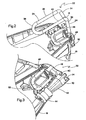
- a multi-position hook assembly is generally designated 22 and is intended for use in the tool 10.
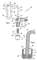
- the hook assembly 22 includes a hook 24 having a free leg 26 and a mounting leg 28 joined and spaced apart by a top span 30.
- the hook assembly 22 includes a holding block 32 that is configured for rotatably receiving the mounting leg 28 of the hook 24 and for releasably locking the hook 24 in more than one position.
- the hook 24 is generally "U"-shaped and preferably constructed from a single length of formed wire. However, other materials and fabrication techniques are contemplated.
- the free leg 26 and the mounting leg 28 are generally parallel with respect to each other.
- the free leg 26 includes a top member 34, a bottom member 36, and two side members 38 and 40, all of which are generally coplanar with respect to each other.
- the top member 34, the bottom member 36, and the two side members 38 and 40 are generally positioned to form a generally closed rectanguloid shape. It can also be seen that the top member 34 is only attached to one side member 38 and a free end 41 abuts the side member 40 (see FIG. 2 ).
- the configuration of the free leg 26 is designed to allow users to slip the free leg of the hook 24 onto their belt.
- the mounting leg 28 of the hook 24 also has a mounting formation 42 configured for engaging a stop button 44.
- An annular groove is shown FIG. 4 as the preferred type of the mounting formation 42 and engages the stop button in a snap fit (see FIG. 5 ).
- the present invention is not limited to only this type of securing structure.
- the holding block 32 is configured for rotatably receiving the mounting leg 28 of the hook 24 and for releasably locking the hook 24 in a selected position. More specifically, the holding block 32 has a supporting span 46 that is castellated for supporting the hook 24 in more than one position. Additionally, the holding block 32 further includes an attaching arm 48 and a nose end 50 that are connected to the supporting span 46 so that the nose end 50 and the attaching arm 48 are in generally spaced, parallel relationship to each other. A nose end throughbore 52 (shown hidden) passes through the supporting span 46 and the nose end 50 of the holding block 32 and allows insertion of the mounting leg 28 for slidable and rotatable engagement.
- the attaching arm 48 secures the hook assembly 22 to the tool 10. This is accomplished by inserting the attaching arm 48 between the two halves of the handle housing 18 of the tool 10. Specialized receiving formations 53 in each housing half receive, capture, and support the attaching arm 48 upon assembly of the housing 18.
- the hook 24 can be rotated and releasably locked into three different positions.
- the first position shown in phantom
- the supporting span 46 of the holding block 32 supports the hook 24.
- a notch 54 of the supporting span 46 only supports an end 56 of the top span 30 of the hook 24 when the hook is in the first position.
- the first position is designed so that the hook 24 projects normally from the housing 12 and the top span 30 has sufficient length for attachment to framing members, rafters, trusses, ladders, handrails, bracings, plywood sheets or other similar structures.
- the supporting span 46 of the holding block 32 and the tool 10 support the hook 24. More specifically, the castellated supporting span 46 defines a longitudinal track 58.
- the top span 30 is accommodated and supported in the track 58 ( FIG. 1 ).
- the track 58 extends from the notch 54 to a second end 60 of the holding block 32.
- the track widens as it approaches the end 60, however other lengths and configurations are contemplated provided the hook 24 is adequately supported.
- the second position is designed so that the free leg 26 of the hook 24 can be attached to a user's belt.
- first position and the second position of the hook 24 are positioned approximately 180° from each other on the holding block 32, however other angular orientations are contemplated depending on the application.
- the tool 10 is preferably a power tool of the type having a battery, and when the hook 22 releasably locks into a third position (depicted in solid lines), the hook 22 is in an operational relationship to the battery. More specifically, when the hook 22 is in the third position, the free leg 26 of the hook 22 holds the battery in the battery housing 14.
- a second notch 62 is provided in the supporting span 46 in close proximity to the notch 54. As such, the notch 62 also supports the end 56 of the top span 30.
- standby mode means that the tool is not actively in use. In standby mode, users often deliberately disengage the battery to preserve battery life.
- the third position is approximately 90° from either the first position or the second position on the holding block 32.
- the stop button 44 is configured for receiving the mounting leg 28 of the hook 24.
- the button 44 has a stop button throughbore 64 and a cavity 66 with an opening 68 at one end.
- the cavity 66 has a cavity mounting formation 70 that is configured for engaging the mounting leg mounting formation 42. More specifically, FIG. 5 shows the mounting formation 70 as an annular, inwardly projecting rib engaging an annular groove 42.
- the present hook assembly 22 is not limited to this mounting formation.
- the hook assembly 22 further includes a biasing element 72 for releasably biasing the hook 24 in one or more positions. Furthermore, the hook assembly 22 also includes a biasing element chamber 74 defined by a counterbore 76 (shown hidden) in the nose end 50 of the holding block 32, and the cavity 66 of the stop button 44 for retaining the biasing element 72.
- the biasing element 72 is a compression spring, but any suitable biasing element can be used in the present invention.
- the biasing element 72 is substantially enclosed when it is inside of the biasing element chamber 74.
- biasing element 72 is enclosed in the nose end counterbore 76, and another, opposite portion of the biasing element is enclosed in the cavity 66 of the stop button 44. Finally, when the stop button 44 is depressed, the force of the biasing element 72 is overcome, and the hook 24 is rotatable and releasably lockable into one or more selected positions as described above.
Landscapes
- Engineering & Computer Science (AREA)
- Mechanical Engineering (AREA)
- Workshop Equipment, Work Benches, Supports, Or Storage Means (AREA)
- Hooks, Suction Cups, And Attachment By Adhesive Means (AREA)
- Conveying And Assembling Of Building Elements In Situ (AREA)
- Supports Or Holders For Household Use (AREA)
Applications Claiming Priority (1)
| Application Number | Priority Date | Filing Date | Title |
|---|---|---|---|
| US10/958,786 US7306052B2 (en) | 2004-10-05 | 2004-10-05 | Multi-position utility hook assembly for tool |
Publications (2)
| Publication Number | Publication Date |
|---|---|
| EP1645372A1 EP1645372A1 (en) | 2006-04-12 |
| EP1645372B1 true EP1645372B1 (en) | 2008-09-17 |
Family
ID=35515681
Family Applications (1)
| Application Number | Title | Priority Date | Filing Date |
|---|---|---|---|
| EP05292069A Expired - Lifetime EP1645372B1 (en) | 2004-10-05 | 2005-10-05 | Multi-position utility hook assembly for tool |
Country Status (8)
| Country | Link |
|---|---|
| US (1) | US7306052B2 (da) |
| EP (1) | EP1645372B1 (da) |
| AT (1) | ATE408483T1 (da) |
| AU (1) | AU2005219743B2 (da) |
| CA (1) | CA2516862C (da) |
| DE (1) | DE602005009778D1 (da) |
| DK (1) | DK1645372T3 (da) |
| NZ (1) | NZ542836A (da) |
Cited By (1)
| Publication number | Priority date | Publication date | Assignee | Title |
|---|---|---|---|---|
| USD582743S1 (en) | 2006-05-26 | 2008-12-16 | Black & Decker Inc. | Nailer |
Families Citing this family (45)
| Publication number | Priority date | Publication date | Assignee | Title |
|---|---|---|---|---|
| FR2868920B1 (fr) * | 2004-04-14 | 2006-12-22 | Prospection Et D Inv S Techniq | Ensemble d'un outil portatif a actionnement manuel et d'un accessoire d'accrochage de l'outil et l'accessoire d'accrochage |
| US8070027B2 (en) * | 2005-04-25 | 2011-12-06 | Piatt Sr John A | Adaptable tool hook |
| USD556003S1 (en) | 2006-05-26 | 2007-11-27 | Black & Decker Inc. | Nailer |
| US7942299B2 (en) * | 2006-05-31 | 2011-05-17 | Black & Decker Inc. | Hand tool with belt or rafter hook |
| US20080000939A1 (en) * | 2006-06-28 | 2008-01-03 | Sean Michael Walsh | Universal ergonomic tool holder |
| US7617960B2 (en) * | 2006-07-21 | 2009-11-17 | Gary Clark | Tool mounting device and method of mounting a tool |
| JP4844831B2 (ja) * | 2006-11-24 | 2011-12-28 | 日立工機株式会社 | 動力工具 |
| EP2022607B1 (en) * | 2007-07-26 | 2011-03-09 | Makita Corporation | Hook structure of power tool |
| JP5188873B2 (ja) * | 2008-05-09 | 2013-04-24 | 株式会社マキタ | 携帯工具 |
| US8387846B2 (en) | 2009-06-08 | 2013-03-05 | Illinois Tool Works Inc | Fastening tool with blind guide work contact tip |
| US8261847B2 (en) * | 2009-10-09 | 2012-09-11 | Illinois Tool Works Inc. | Automatic low power consumption mode for combustion tools |
| JP5555594B2 (ja) * | 2010-10-07 | 2014-07-23 | 株式会社マキタ | 電動工具用吊り下げ具及び電動工具用吊り下げ具を装着した電動工具 |
| US9522464B2 (en) * | 2011-05-16 | 2016-12-20 | Illinois Tool Works Inc. | Multi-position utility hook assembly for a tool |
| US8998057B2 (en) | 2011-08-19 | 2015-04-07 | Techtronic Power Tools Technology Limited | Hook assembly for use with a power tool |
| JP2013059837A (ja) * | 2011-09-14 | 2013-04-04 | Makita Corp | 動力工具及びその吊下げ具 |
| US8905572B2 (en) | 2012-03-28 | 2014-12-09 | Milwaukee Electric Tool Corporation | Portable light, such as a stick light |
| CA2842041A1 (en) * | 2012-04-18 | 2013-10-24 | Arrowhead Research Corporation | Poly(acrylate) polymers for in vivo nucleic acid delivery |
| US8960635B2 (en) | 2012-10-04 | 2015-02-24 | Black & Decker Inc. | Rafter hook for fastening tool |
| US8740255B1 (en) * | 2012-12-18 | 2014-06-03 | Timothy Allen Harris | Air tool hook |
| US9457461B2 (en) * | 2013-08-06 | 2016-10-04 | Robert Bosch Tool Corporation | Dual axis hook assembly for a power tool |
| USD725981S1 (en) | 2013-10-29 | 2015-04-07 | Black & Decker Inc. | Screwdriver with nosepiece |
| US20150151424A1 (en) | 2013-10-29 | 2015-06-04 | Black & Decker Inc. | Power tool with ergonomic handgrip |
| AU362572S (en) | 2014-11-26 | 2015-07-15 | Techtronic Ind Co Ltd | Battery |
| US10668608B2 (en) | 2016-02-10 | 2020-06-02 | Illinois Tool Works Inc. | Fastener driving tool |
| US9889547B2 (en) | 2016-02-24 | 2018-02-13 | Worktools, Inc. | Selective deployable tool hook |
| EP3434421A1 (de) * | 2017-07-28 | 2019-01-30 | HILTI Aktiengesellschaft | Hakenhalterung für eine werkzeugmaschine |
| US10926391B2 (en) | 2017-11-14 | 2021-02-23 | Illinois Tool Works Inc. | Powered fastener driving tool having hook assemblies |
| USD855431S1 (en) | 2017-11-14 | 2019-08-06 | Illinois Tool Works Inc. | Fastener driving tool pipe hook |
| USD854820S1 (en) | 2017-11-14 | 2019-07-30 | Illinois Tool Works Inc. | Fastener driving tool belt hook |
| EP3520975B1 (de) * | 2018-02-06 | 2022-01-05 | Andreas Stihl AG & Co. KG | Garten- und/oder forstgerät |
| US10759034B2 (en) * | 2018-02-15 | 2020-09-01 | James Hardie Technology Limited | Systems and methods for fastening a component to a building substrate |
| JP7123592B2 (ja) * | 2018-03-23 | 2022-08-23 | 株式会社マキタ | 電動工具および電動工具の結合具 |
| US11964356B2 (en) * | 2018-04-05 | 2024-04-23 | Makita Corporation | Hand-held tool |
| US10576616B2 (en) | 2018-05-07 | 2020-03-03 | Black & Decker Inc. | Power tool wire form hook assembly |
| JP7237509B2 (ja) * | 2018-10-05 | 2023-03-13 | 株式会社マキタ | 動力工具およびフック |
| JP7337530B2 (ja) * | 2019-04-05 | 2023-09-04 | 株式会社マキタ | 動力工具および工具保持具 |
| USD972388S1 (en) | 2020-04-20 | 2022-12-13 | Milwaukee Electric Tool Corporation | Hydraulic tool |
| CN219902016U (zh) | 2020-04-20 | 2023-10-27 | 米沃奇电动工具公司 | 液压工具 |
| US12233523B2 (en) | 2020-12-07 | 2025-02-25 | Black & Decker Inc. | Power tool with multiple modes of operation and ergonomic handgrip |
| CN114683218B (zh) * | 2020-12-29 | 2025-08-29 | 喜利得股份公司 | 用于动力工具的挂钩组件 |
| CN215470913U (zh) * | 2021-05-21 | 2022-01-11 | 浙江普莱得电器股份有限公司 | 一种伸缩悬挂组件 |
| USD1088790S1 (en) * | 2021-10-18 | 2025-08-19 | Midwest Innovative Products, Llc | Tool holder |
| WO2023158729A1 (en) | 2022-02-18 | 2023-08-24 | Milwaukee Electric Tool Corporation | Powered fastener driver |
| JP7773095B2 (ja) * | 2022-02-28 | 2025-11-19 | 工機ホールディングス株式会社 | 作業機 |
| DE102024112566A1 (de) | 2023-05-05 | 2024-11-07 | Milwaukee Electric Tool Corporation | Fremdkraftbetätigter befestigungsmitteleintreiber |
Family Cites Families (18)
| Publication number | Priority date | Publication date | Assignee | Title |
|---|---|---|---|---|
| US2803048A (en) * | 1953-11-09 | 1957-08-20 | Ft Products Ltd | Fastener |
| US3797229A (en) * | 1972-09-25 | 1974-03-19 | Nixdorff Krein Mfg | Connector hook |
| US4372468A (en) * | 1981-05-08 | 1983-02-08 | Mcguire-Nicholas Manufacturing Company | Tool holder |
| US4406064A (en) | 1981-06-15 | 1983-09-27 | Goss Duke W | Gravity stabilized portable power tool hanger |
| US4457462A (en) | 1981-08-26 | 1984-07-03 | Taormina Umberto C | Tool holder |
| US4787145A (en) | 1987-03-09 | 1988-11-29 | Klicker Garry L | Two position portable power tool hanger stabilized by spring and detent |
| US5743451A (en) * | 1996-04-29 | 1998-04-28 | Kahn; Peter P. | Tool belt tool tote |
| US5944242A (en) * | 1996-05-16 | 1999-08-31 | Musarella; Michael | Tool holder |
| US5850698A (en) * | 1997-05-30 | 1998-12-22 | Black & Decker Inc. | Portable circular saw |
| US6325577B1 (en) * | 1998-10-28 | 2001-12-04 | Wayne Anderson | Magnetizer/demagnetizer and tool hook attachable tool bit holder |
| DE19856266A1 (de) | 1998-12-07 | 2000-06-08 | Hilti Ag | Elektrisch betreibbares Handgerät |
| JP3853551B2 (ja) | 1999-12-06 | 2006-12-06 | 株式会社マキタ | 釘打ち機 |
| US6454147B1 (en) * | 2000-05-12 | 2002-09-24 | Worktools, Inc. | Personal tool carrying device |
| JP3553585B2 (ja) * | 2001-03-02 | 2004-08-11 | 日立工機株式会社 | 電動工具 |
| US20020179659A1 (en) | 2001-06-04 | 2002-12-05 | Shaw Stanly G. | Tool support and lock |
| US6722549B2 (en) | 2002-05-08 | 2004-04-20 | Yury Shkolnikov | Arm member for fastener driving tool |
| US20040050888A1 (en) | 2002-09-13 | 2004-03-18 | Philip Warner | Universal tool support apparatus and methods |
| US20040178240A1 (en) | 2003-03-12 | 2004-09-16 | Bauer Ernest A. | Tool belt tote |
-
2004
- 2004-10-05 US US10/958,786 patent/US7306052B2/en not_active Expired - Lifetime
-
2005
- 2005-08-23 CA CA002516862A patent/CA2516862C/en not_active Expired - Fee Related
- 2005-10-03 AU AU2005219743A patent/AU2005219743B2/en not_active Expired
- 2005-10-05 EP EP05292069A patent/EP1645372B1/en not_active Expired - Lifetime
- 2005-10-05 AT AT05292069T patent/ATE408483T1/de not_active IP Right Cessation
- 2005-10-05 DK DK05292069T patent/DK1645372T3/da active
- 2005-10-05 DE DE602005009778T patent/DE602005009778D1/de not_active Expired - Lifetime
- 2005-10-06 NZ NZ542836A patent/NZ542836A/en not_active IP Right Cessation
Cited By (1)
| Publication number | Priority date | Publication date | Assignee | Title |
|---|---|---|---|---|
| USD582743S1 (en) | 2006-05-26 | 2008-12-16 | Black & Decker Inc. | Nailer |
Also Published As
| Publication number | Publication date |
|---|---|
| AU2005219743B2 (en) | 2007-06-07 |
| DK1645372T3 (da) | 2009-01-26 |
| US20060070761A1 (en) | 2006-04-06 |
| CA2516862C (en) | 2008-11-18 |
| ATE408483T1 (de) | 2008-10-15 |
| CA2516862A1 (en) | 2006-04-05 |
| US7306052B2 (en) | 2007-12-11 |
| NZ542836A (en) | 2007-04-27 |
| AU2005219743A1 (en) | 2006-04-27 |
| EP1645372A1 (en) | 2006-04-12 |
| DE602005009778D1 (de) | 2008-10-30 |
Similar Documents
| Publication | Publication Date | Title |
|---|---|---|
| EP1645372B1 (en) | Multi-position utility hook assembly for tool | |
| US10427289B2 (en) | Multi-position utility hook assembly for a tool | |
| US7314153B2 (en) | Belt mounted tool holder | |
| US6644825B2 (en) | Nail-driving tool with an illumination device | |
| US7654430B2 (en) | Coil nailing device for construction finishing materials | |
| US6564903B2 (en) | Collapsable sawhorse bracket with interleaving legs | |
| US6045102A (en) | Multi-purpose ladder and roof device | |
| US8770778B2 (en) | Utility light kit for attachment to the top of a ladder | |
| US10531724B2 (en) | Belt clip for power tool | |
| US7942299B2 (en) | Hand tool with belt or rafter hook | |
| US5931318A (en) | Tool bit holder | |
| US6116419A (en) | Ladder pouch | |
| JP2003326476A (ja) | 動力工具 | |
| US20070272811A1 (en) | Roof safety device | |
| US6279741B1 (en) | Cordless power tool holder | |
| EP2678137B1 (en) | Tool supporting apparatus | |
| US6539831B2 (en) | Circular power saw | |
| US7290655B1 (en) | Carrying case assembly for a power tool and its associated method of use | |
| US20250178182A1 (en) | Cordless Driver Holder Device | |
| US7293489B1 (en) | Carrying case assembly for a circular saw and its associated method of use | |
| US20240025024A1 (en) | Cordless electric coil roofing nail gun apparatus | |
| US5490649A (en) | Devise for mounting, securing and supporting portable power tools having bed extension assemblies | |
| EP4667165A1 (en) | A hanger accessory and hanger system | |
| US20250295221A1 (en) | Combination hammer/tool holder | |
| CA2356507A1 (en) | Improved rotational hanger for power tool |
Legal Events
| Date | Code | Title | Description |
|---|---|---|---|
| PUAI | Public reference made under article 153(3) epc to a published international application that has entered the european phase |
Free format text: ORIGINAL CODE: 0009012 |
|
| AK | Designated contracting states |
Kind code of ref document: A1 Designated state(s): AT BE BG CH CY CZ DE DK EE ES FI FR GB GR HU IE IS IT LI LT LU LV MC NL PL PT RO SE SI SK TR |
|
| AX | Request for extension of the european patent |
Extension state: AL BA HR MK YU |
|
| 17P | Request for examination filed |
Effective date: 20061002 |
|
| 17Q | First examination report despatched |
Effective date: 20061102 |
|
| AKX | Designation fees paid |
Designated state(s): AT BE BG CH CY CZ DE DK EE ES FI FR GB GR HU IE IS IT LI LT LU LV MC NL PL PT RO SE SI SK TR |
|
| GRAP | Despatch of communication of intention to grant a patent |
Free format text: ORIGINAL CODE: EPIDOSNIGR1 |
|
| GRAS | Grant fee paid |
Free format text: ORIGINAL CODE: EPIDOSNIGR3 |
|
| GRAA | (expected) grant |
Free format text: ORIGINAL CODE: 0009210 |
|
| AK | Designated contracting states |
Kind code of ref document: B1 Designated state(s): AT BE BG CH CY CZ DE DK EE ES FI FR GB GR HU IE IS IT LI LT LU LV MC NL PL PT RO SE SI SK TR |
|
| REG | Reference to a national code |
Ref country code: GB Ref legal event code: FG4D |
|
| REG | Reference to a national code |
Ref country code: CH Ref legal event code: EP |
|
| REG | Reference to a national code |
Ref country code: IE Ref legal event code: FG4D |
|
| REF | Corresponds to: |
Ref document number: 602005009778 Country of ref document: DE Date of ref document: 20081030 Kind code of ref document: P |
|
| REG | Reference to a national code |
Ref country code: SE Ref legal event code: TRGR |
|
| REG | Reference to a national code |
Ref country code: DK Ref legal event code: T3 |
|
| PG25 | Lapsed in a contracting state [announced via postgrant information from national office to epo] |
Ref country code: LT Free format text: LAPSE BECAUSE OF FAILURE TO SUBMIT A TRANSLATION OF THE DESCRIPTION OR TO PAY THE FEE WITHIN THE PRESCRIBED TIME-LIMIT Effective date: 20080917 |
|
| PG25 | Lapsed in a contracting state [announced via postgrant information from national office to epo] |
Ref country code: FI Free format text: LAPSE BECAUSE OF FAILURE TO SUBMIT A TRANSLATION OF THE DESCRIPTION OR TO PAY THE FEE WITHIN THE PRESCRIBED TIME-LIMIT Effective date: 20080917 Ref country code: SI Free format text: LAPSE BECAUSE OF FAILURE TO SUBMIT A TRANSLATION OF THE DESCRIPTION OR TO PAY THE FEE WITHIN THE PRESCRIBED TIME-LIMIT Effective date: 20080917 Ref country code: LV Free format text: LAPSE BECAUSE OF FAILURE TO SUBMIT A TRANSLATION OF THE DESCRIPTION OR TO PAY THE FEE WITHIN THE PRESCRIBED TIME-LIMIT Effective date: 20080917 Ref country code: AT Free format text: LAPSE BECAUSE OF FAILURE TO SUBMIT A TRANSLATION OF THE DESCRIPTION OR TO PAY THE FEE WITHIN THE PRESCRIBED TIME-LIMIT Effective date: 20080917 |
|
| PG25 | Lapsed in a contracting state [announced via postgrant information from national office to epo] |
Ref country code: ES Free format text: LAPSE BECAUSE OF FAILURE TO SUBMIT A TRANSLATION OF THE DESCRIPTION OR TO PAY THE FEE WITHIN THE PRESCRIBED TIME-LIMIT Effective date: 20081228 Ref country code: BG Free format text: LAPSE BECAUSE OF FAILURE TO SUBMIT A TRANSLATION OF THE DESCRIPTION OR TO PAY THE FEE WITHIN THE PRESCRIBED TIME-LIMIT Effective date: 20081217 |
|
| PG25 | Lapsed in a contracting state [announced via postgrant information from national office to epo] |
Ref country code: SK Free format text: LAPSE BECAUSE OF FAILURE TO SUBMIT A TRANSLATION OF THE DESCRIPTION OR TO PAY THE FEE WITHIN THE PRESCRIBED TIME-LIMIT Effective date: 20080917 Ref country code: RO Free format text: LAPSE BECAUSE OF FAILURE TO SUBMIT A TRANSLATION OF THE DESCRIPTION OR TO PAY THE FEE WITHIN THE PRESCRIBED TIME-LIMIT Effective date: 20080917 Ref country code: CZ Free format text: LAPSE BECAUSE OF FAILURE TO SUBMIT A TRANSLATION OF THE DESCRIPTION OR TO PAY THE FEE WITHIN THE PRESCRIBED TIME-LIMIT Effective date: 20080917 Ref country code: PT Free format text: LAPSE BECAUSE OF FAILURE TO SUBMIT A TRANSLATION OF THE DESCRIPTION OR TO PAY THE FEE WITHIN THE PRESCRIBED TIME-LIMIT Effective date: 20090217 Ref country code: IS Free format text: LAPSE BECAUSE OF FAILURE TO SUBMIT A TRANSLATION OF THE DESCRIPTION OR TO PAY THE FEE WITHIN THE PRESCRIBED TIME-LIMIT Effective date: 20090117 Ref country code: MC Free format text: LAPSE BECAUSE OF NON-PAYMENT OF DUE FEES Effective date: 20081031 |
|
| PLBE | No opposition filed within time limit |
Free format text: ORIGINAL CODE: 0009261 |
|
| STAA | Information on the status of an ep patent application or granted ep patent |
Free format text: STATUS: NO OPPOSITION FILED WITHIN TIME LIMIT |
|
| PG25 | Lapsed in a contracting state [announced via postgrant information from national office to epo] |
Ref country code: EE Free format text: LAPSE BECAUSE OF FAILURE TO SUBMIT A TRANSLATION OF THE DESCRIPTION OR TO PAY THE FEE WITHIN THE PRESCRIBED TIME-LIMIT Effective date: 20080917 |
|
| 26N | No opposition filed |
Effective date: 20090618 |
|
| PG25 | Lapsed in a contracting state [announced via postgrant information from national office to epo] |
Ref country code: IT Free format text: LAPSE BECAUSE OF FAILURE TO SUBMIT A TRANSLATION OF THE DESCRIPTION OR TO PAY THE FEE WITHIN THE PRESCRIBED TIME-LIMIT Effective date: 20080917 |
|
| PG25 | Lapsed in a contracting state [announced via postgrant information from national office to epo] |
Ref country code: IE Free format text: LAPSE BECAUSE OF NON-PAYMENT OF DUE FEES Effective date: 20081005 |
|
| PG25 | Lapsed in a contracting state [announced via postgrant information from national office to epo] |
Ref country code: PL Free format text: LAPSE BECAUSE OF FAILURE TO SUBMIT A TRANSLATION OF THE DESCRIPTION OR TO PAY THE FEE WITHIN THE PRESCRIBED TIME-LIMIT Effective date: 20080917 |
|
| REG | Reference to a national code |
Ref country code: CH Ref legal event code: PL |
|
| PG25 | Lapsed in a contracting state [announced via postgrant information from national office to epo] |
Ref country code: HU Free format text: LAPSE BECAUSE OF FAILURE TO SUBMIT A TRANSLATION OF THE DESCRIPTION OR TO PAY THE FEE WITHIN THE PRESCRIBED TIME-LIMIT Effective date: 20090318 Ref country code: CY Free format text: LAPSE BECAUSE OF FAILURE TO SUBMIT A TRANSLATION OF THE DESCRIPTION OR TO PAY THE FEE WITHIN THE PRESCRIBED TIME-LIMIT Effective date: 20080917 Ref country code: LU Free format text: LAPSE BECAUSE OF NON-PAYMENT OF DUE FEES Effective date: 20081005 |
|
| PG25 | Lapsed in a contracting state [announced via postgrant information from national office to epo] |
Ref country code: TR Free format text: LAPSE BECAUSE OF FAILURE TO SUBMIT A TRANSLATION OF THE DESCRIPTION OR TO PAY THE FEE WITHIN THE PRESCRIBED TIME-LIMIT Effective date: 20080917 |
|
| PG25 | Lapsed in a contracting state [announced via postgrant information from national office to epo] |
Ref country code: LI Free format text: LAPSE BECAUSE OF NON-PAYMENT OF DUE FEES Effective date: 20091031 Ref country code: CH Free format text: LAPSE BECAUSE OF NON-PAYMENT OF DUE FEES Effective date: 20091031 Ref country code: GR Free format text: LAPSE BECAUSE OF FAILURE TO SUBMIT A TRANSLATION OF THE DESCRIPTION OR TO PAY THE FEE WITHIN THE PRESCRIBED TIME-LIMIT Effective date: 20081218 |
|
| REG | Reference to a national code |
Ref country code: FR Ref legal event code: PLFP Year of fee payment: 11 |
|
| REG | Reference to a national code |
Ref country code: FR Ref legal event code: PLFP Year of fee payment: 12 |
|
| REG | Reference to a national code |
Ref country code: FR Ref legal event code: PLFP Year of fee payment: 13 |
|
| REG | Reference to a national code |
Ref country code: FR Ref legal event code: PLFP Year of fee payment: 14 |
|
| P01 | Opt-out of the competence of the unified patent court (upc) registered |
Effective date: 20230606 |
|
| PGFP | Annual fee paid to national office [announced via postgrant information from national office to epo] |
Ref country code: NL Payment date: 20241026 Year of fee payment: 20 |
|
| PGFP | Annual fee paid to national office [announced via postgrant information from national office to epo] |
Ref country code: DE Payment date: 20241029 Year of fee payment: 20 |
|
| PGFP | Annual fee paid to national office [announced via postgrant information from national office to epo] |
Ref country code: DK Payment date: 20241025 Year of fee payment: 20 |
|
| PGFP | Annual fee paid to national office [announced via postgrant information from national office to epo] |
Ref country code: BE Payment date: 20241028 Year of fee payment: 20 |
|
| PGFP | Annual fee paid to national office [announced via postgrant information from national office to epo] |
Ref country code: GB Payment date: 20241028 Year of fee payment: 20 |
|
| PGFP | Annual fee paid to national office [announced via postgrant information from national office to epo] |
Ref country code: FR Payment date: 20241025 Year of fee payment: 20 |
|
| PGFP | Annual fee paid to national office [announced via postgrant information from national office to epo] |
Ref country code: SE Payment date: 20241027 Year of fee payment: 20 |
|
| REG | Reference to a national code |
Ref country code: DE Ref legal event code: R071 Ref document number: 602005009778 Country of ref document: DE |
|
| REG | Reference to a national code |
Ref country code: DK Ref legal event code: EUP Expiry date: 20251005 |
|
| REG | Reference to a national code |
Ref country code: NL Ref legal event code: MK Effective date: 20251004 |
|
| REG | Reference to a national code |
Ref country code: GB Ref legal event code: PE20 Expiry date: 20251004 |
|
| REG | Reference to a national code |
Ref country code: SE Ref legal event code: EUG |
|
| REG | Reference to a national code |
Ref country code: BE Ref legal event code: MK Effective date: 20251005 |