EP1645532A1 - Procédé et dispositif de fabrication d'un enroulement de matériau non-tissée - Google Patents
Procédé et dispositif de fabrication d'un enroulement de matériau non-tissée Download PDFInfo
- Publication number
- EP1645532A1 EP1645532A1 EP05021703A EP05021703A EP1645532A1 EP 1645532 A1 EP1645532 A1 EP 1645532A1 EP 05021703 A EP05021703 A EP 05021703A EP 05021703 A EP05021703 A EP 05021703A EP 1645532 A1 EP1645532 A1 EP 1645532A1
- Authority
- EP
- European Patent Office
- Prior art keywords
- winding
- nonwoven fabric
- roller
- band
- loop
- Prior art date
- Legal status (The legal status is an assumption and is not a legal conclusion. Google has not performed a legal analysis and makes no representation as to the accuracy of the status listed.)
- Withdrawn
Links
- 238000000034 method Methods 0.000 title claims abstract description 70
- 239000000463 material Substances 0.000 title claims description 10
- 238000004519 manufacturing process Methods 0.000 title claims description 9
- 238000004804 winding Methods 0.000 claims abstract description 138
- 239000004745 nonwoven fabric Substances 0.000 claims description 104
- 239000000835 fiber Substances 0.000 claims description 89
- 239000011490 mineral wool Substances 0.000 claims description 19
- 239000011491 glass wool Substances 0.000 claims description 15
- 238000009413 insulation Methods 0.000 claims description 15
- 239000002557 mineral fiber Substances 0.000 claims description 12
- 230000002829 reductive effect Effects 0.000 claims description 12
- 230000000284 resting effect Effects 0.000 claims description 6
- 229910052751 metal Inorganic materials 0.000 claims description 3
- 239000002184 metal Substances 0.000 claims description 3
- 230000002093 peripheral effect Effects 0.000 claims description 2
- 239000004033 plastic Substances 0.000 claims description 2
- 229920003023 plastic Polymers 0.000 claims description 2
- 239000004744 fabric Substances 0.000 abstract 4
- 238000007906 compression Methods 0.000 description 22
- 230000006835 compression Effects 0.000 description 20
- 239000011810 insulating material Substances 0.000 description 17
- 239000011230 binding agent Substances 0.000 description 10
- 239000003365 glass fiber Substances 0.000 description 5
- 239000000203 mixture Substances 0.000 description 4
- 238000004806 packaging method and process Methods 0.000 description 4
- 238000005096 rolling process Methods 0.000 description 4
- 238000011144 upstream manufacturing Methods 0.000 description 4
- 239000004698 Polyethylene Substances 0.000 description 3
- 238000010276 construction Methods 0.000 description 3
- 238000013461 design Methods 0.000 description 3
- 238000011161 development Methods 0.000 description 3
- 238000009826 distribution Methods 0.000 description 3
- 230000000694 effects Effects 0.000 description 3
- 238000003860 storage Methods 0.000 description 3
- 229920001187 thermosetting polymer Polymers 0.000 description 3
- 239000000654 additive Substances 0.000 description 2
- 239000000853 adhesive Substances 0.000 description 2
- 230000001070 adhesive effect Effects 0.000 description 2
- 230000006837 decompression Effects 0.000 description 2
- 239000002245 particle Substances 0.000 description 2
- -1 polyethylene Polymers 0.000 description 2
- 229920000573 polyethylene Polymers 0.000 description 2
- 229920001807 Urea-formaldehyde Polymers 0.000 description 1
- 229910052782 aluminium Inorganic materials 0.000 description 1
- XAGFODPZIPBFFR-UHFFFAOYSA-N aluminium Chemical compound [Al] XAGFODPZIPBFFR-UHFFFAOYSA-N 0.000 description 1
- 238000013459 approach Methods 0.000 description 1
- 238000005452 bending Methods 0.000 description 1
- 230000015572 biosynthetic process Effects 0.000 description 1
- 239000002131 composite material Substances 0.000 description 1
- 230000008021 deposition Effects 0.000 description 1
- 239000000428 dust Substances 0.000 description 1
- 239000000839 emulsion Substances 0.000 description 1
- 230000002349 favourable effect Effects 0.000 description 1
- 239000011152 fibreglass Substances 0.000 description 1
- 239000002657 fibrous material Substances 0.000 description 1
- 239000011888 foil Substances 0.000 description 1
- LCDFWRDNEPDQBV-UHFFFAOYSA-N formaldehyde;phenol;urea Chemical compound O=C.NC(N)=O.OC1=CC=CC=C1 LCDFWRDNEPDQBV-UHFFFAOYSA-N 0.000 description 1
- 239000000156 glass melt Substances 0.000 description 1
- 238000003780 insertion Methods 0.000 description 1
- 230000037431 insertion Effects 0.000 description 1
- 239000012774 insulation material Substances 0.000 description 1
- 239000002480 mineral oil Substances 0.000 description 1
- 235000010446 mineral oil Nutrition 0.000 description 1
- 239000003921 oil Substances 0.000 description 1
- 230000003287 optical effect Effects 0.000 description 1
- 230000036961 partial effect Effects 0.000 description 1
- 239000002985 plastic film Substances 0.000 description 1
- 229920006255 plastic film Polymers 0.000 description 1
- 238000003825 pressing Methods 0.000 description 1
- 238000002203 pretreatment Methods 0.000 description 1
- 238000012545 processing Methods 0.000 description 1
- 230000001737 promoting effect Effects 0.000 description 1
- 230000035484 reaction time Effects 0.000 description 1
- 230000008707 rearrangement Effects 0.000 description 1
- 230000002787 reinforcement Effects 0.000 description 1
- 229920005989 resin Polymers 0.000 description 1
- 239000011347 resin Substances 0.000 description 1
- 230000002441 reversible effect Effects 0.000 description 1
- 229920002545 silicone oil Polymers 0.000 description 1
- 239000007858 starting material Substances 0.000 description 1
- 230000003068 static effect Effects 0.000 description 1
- 239000000126 substance Substances 0.000 description 1
- 239000000725 suspension Substances 0.000 description 1
Images

Classifications
-
- B—PERFORMING OPERATIONS; TRANSPORTING
- B65—CONVEYING; PACKING; STORING; HANDLING THIN OR FILAMENTARY MATERIAL
- B65H—HANDLING THIN OR FILAMENTARY MATERIAL, e.g. SHEETS, WEBS, CABLES
- B65H18/00—Winding webs
- B65H18/08—Web-winding mechanisms
- B65H18/14—Mechanisms in which power is applied to web roll, e.g. to effect continuous advancement of web
- B65H18/22—Mechanisms in which power is applied to web roll, e.g. to effect continuous advancement of web by friction band
-
- B—PERFORMING OPERATIONS; TRANSPORTING
- B65—CONVEYING; PACKING; STORING; HANDLING THIN OR FILAMENTARY MATERIAL
- B65B—MACHINES, APPARATUS OR DEVICES FOR, OR METHODS OF, PACKAGING ARTICLES OR MATERIALS; UNPACKING
- B65B63/00—Auxiliary devices, not otherwise provided for, for operating on articles or materials to be packaged
- B65B63/02—Auxiliary devices, not otherwise provided for, for operating on articles or materials to be packaged for compressing or compacting articles or materials prior to wrapping or insertion in containers or receptacles
- B65B63/024—Auxiliary devices, not otherwise provided for, for operating on articles or materials to be packaged for compressing or compacting articles or materials prior to wrapping or insertion in containers or receptacles for compressing by winding
-
- B—PERFORMING OPERATIONS; TRANSPORTING
- B65—CONVEYING; PACKING; STORING; HANDLING THIN OR FILAMENTARY MATERIAL
- B65H—HANDLING THIN OR FILAMENTARY MATERIAL, e.g. SHEETS, WEBS, CABLES
- B65H18/00—Winding webs
- B65H18/08—Web-winding mechanisms
- B65H18/26—Mechanisms for controlling contact pressure on winding-web package, e.g. for regulating the quantity of air between web layers
-
- B—PERFORMING OPERATIONS; TRANSPORTING
- B65—CONVEYING; PACKING; STORING; HANDLING THIN OR FILAMENTARY MATERIAL
- B65H—HANDLING THIN OR FILAMENTARY MATERIAL, e.g. SHEETS, WEBS, CABLES
- B65H2701/00—Handled material; Storage means
- B65H2701/10—Handled articles or webs
- B65H2701/17—Nature of material
- B65H2701/177—Fibrous or compressible material
Definitions
- the invention relates to a method for producing a coil of a nonwoven fabric for the thermal and acoustic insulation of buildings, in particular mineral fibers, preferably rock wool and / or glass wool, in which a nonwoven fabric is fed via a conveyor of a winding station, in which a the winding station incoming end of the fibrous web is deflected in a deflection in the direction of the incoming nonwoven fabric, wherein the nonwoven fabric is guided in the winding station to a guide element in the form of a band fitting.
- the invention further relates to a device for producing a coil of a non-woven fabric for the thermal and acoustic insulation of buildings, in particular mineral fibers, preferably rockwool and / or glass wool, with a non-woven in a winding station promotional conveyor, wherein the winding station a deflection receiving a leading into the winding station end of the nonwoven fabric and deflects toward the incoming nonwoven fabric, wherein the deflection device has a guide element in the form of a band which rotates over rollers and during a winding operation against an outer circumferential surface of the coil, wherein a first Roller is arranged in the region of an inlet of the fibrous web in the winding station.
- Non-woven fabrics for the thermal and acoustic insulation of buildings consist of glassy solidified fibers, which are connected to each other with small amounts of a mostly thermosetting binder. Due to the chemical composition of the fibers, a distinction is made between glass wool and rock wool. Because of the favorable processing properties, glass wool can be produced by the spin-blow process. In this case, a glass melt exits through openings of a rotating shell. This process results in longer smooth fibers, which are laid flat on a conveyor belt. Glass wool is usually used with about 5 to 8% by weight of a thermosetting hardening mixture of phenol-formaldehyde urea resins bound.
- the fiber mass is impregnated with about 0.2 to 0.4% by mass of mineral oil, oil emulsions, silicone oil or mixtures thereof.
- mineral oil oil emulsions, silicone oil or mixtures thereof.
- Made of glass wool insulating materials have a pronounced laminar structure with predominantly horizontal storage of monofilaments. Depending on the bulk density and the binder content and the uniformity of the binder distribution, this structure leads to structures with high tensile strength parallel to the large surfaces and low transverse tensile strength or, on the other hand, high compressibility. Relative movements are possible between the horizontally mounted fibers, so that the structures are generally not damaged during winding.
- Glass wool insulating materials with gross densities ⁇ 25 kg / m 3 are available on the market in the form of sheets as well as in the form of rolled insulation felts.
- the rolled-up insulating felts are compressed to reduce the specific volume by about 40 to 60% compared to the initial thickness. After unrolling, the nominal delivery thickness must be reached again, with certain tolerances permissible.
- Such a Dämmfilz is known for example from DE 36 12 587 C2. This known Dämmfilz should have a bulk density between 10 and 40 kg / m 3 and have an increased binder content of 6 to 7% by mass.
- such a Dämmfilz one hand windable and thus flexible, on the other hand, but also have the property that a deflected from the Dämmfilz section has sufficient rigidity, so that this section can be clamped for example between the rafters of pitched roof constructions and holds there at least until immediately following support foils or strips are applied to the underside of the rafters.
- fiber webs which consist of rockwool fibers.
- Such insulating materials usually consist of relatively short, often inherently curved fibers, which are bound with only about 2 to 2.5% by mass of thermosetting resin mixtures or the like.
- the distribution of the binder in the fiber material is generally very uneven even in the fiber webs of rockwool fibers. There are areas with higher binder contents and those with lower proportions in addition to completely binder-free fibers. Even a rough rough estimate shows that the low absolute binder content is by far not sufficient to ideally connect each fiber point by point with the next, so as to bring the elastic properties of the monofilaments to full advantage.
- rockwool nonwovens there are generally about 25 to 33, on average 30% non-fibrous unbonded particles. These particles can not contribute to improving the mechanical properties of the insulating materials. A comparison of the densities of glass and rock wool fiber webs can therefore be made only on the basis of fiber equivalents.
- the structure of the rock wool fiber webs considered here depends on the production method, but in particular also on the method of fiber collection.
- the fibers of rockwool nonwovens which are generally shorter than glass wool monofilaments, can be collected directly on a conveyor belt until the equivalent thickness for the delivery thickness of the insulating material is achieved.
- the technically better solution considering several aspects, is that the collected fibers are as thin as possible primary fleece remove it and then put it on another conveyor, for example by means of a shuttle so that, taking into account the required height and longitudinal compression equivalent deposit heights can be achieved.
- the usual settling transversely to the transport direction results in an oblique storage of the primary nonwoven layers.
- a high number of primary nonwoven layers per unit volume is sought.
- Fiber fleeces of rock wool fibers are relatively stable to pressure substantially in the direction of the three major axes, so that there is a lower compressibility compared to fiber webs of glass fibers.
- nonwoven fabrics made of rock wool have a lower transverse tensile strength in the direction of production compared with nonwoven fabrics made of glass fibers, so that the winding up of nonwoven fibrous webs from rockwool fibers is problematical, especially at high densities of the nonwoven fabric.
- a pressure roll or a pair of pressure rolls may be arranged in front of the winding station.
- this may also be the structure of the fiber fleece be damaged so that the nonwoven fabric already ruptures during winding or falling apart after rolling on site.
- the nonwoven fabric is detected by the upwardly moving belt and abruptly bent by an angle of more than 100 °.
- the pendulum suspended and guided by pressure cylinder tape tears the fiber fleece section and pushes him back to the incoming nonwoven fabric, so that this starts to roll up due to the high friction.
- the nonwoven fabric is additionally subjected to strong shear. Further shear forces are exerted on the already under tension Au- ⁇ enzonen the nonwoven fabric characterized in that the nonwoven fabric is highly compressed and at the same time the winding the winding effecting force is transmitted.
- the introduction of force is limited to a relatively small area of the outer surface.
- the compressive and shear forces have to be high, to achieve a compression of 50 to 70% in the core, to reach on average over the whole insulating roll of 40 to 60%.
- a paper, a PE film or other wrapping material enters the winding station and encases the winding.
- the coated nonwoven fabric is usually glued together firmly to compensate for the significant expansion pressure of the coil.
- an adhesive is preferably applied transversely to the direction of the wrapper.
- the winding process is continued.
- this procedure leads to considerable stresses on the fiber fleece, in particular in the area of the partial surfaces immediately before the end of the insulating material web.
- the nonwoven fabric is subjected to considerable shear, depending on the starting thickness and degree of compression, so that when not sufficient tensile strength ruptures the nonwoven fabric.
- the continuation of the winding process strength breaks up the fiber fleece.
- the continuation of the winding process leads in the region of the free end of the fiber web to a notch-like Auka- ⁇ en.
- the compression of the last winding can be significantly reduced.
- insulating materials with an already higher initial bulk density and a larger internal spring constant for example, rock wool insulation materials, but this approach is less effective if the compression is not reduced by at least 80%.
- the expansion pressure within the coil causes the above-described temporarily elliptical shape of the coil to be converted into a cross-sectionally round shape of the coil following the winding process.
- this expansion pressure also leads to a permanent loading of the area of the fiber fleece, which acts quasi as a clamping point of the fiber fleece.
- the expansion pressure can be partially reduced.
- the compressive coreless winding of fiber webs of mineral fibers is considered to be particularly difficult because the nonwoven fabrics have only a small cohesion due to the short, interlaced mineral fibers and the large proportion of unbound mineral fibers.
- the core of the roll is upset and / or bent to a very high degree.
- Needed for the production of an endless insulating felt web, with non-solidified Binders and other additives impregnated fiber webs are usually not collected directly behind or under a Zerfaserungsmaschine, but mostly only indirectly.
- the thinnest possible primary fiber web is formed and deposited transversely on a second conveyor with the aid of a swinging device.
- the width of the primary fiber web should be as large as possible. A good inner cohesion of the fiber webs is achieved when the width corresponds approximately to their later length.
- Most of the known collection chambers do not have the required widths because they have not been designed from this point of view.
- Fiber webs are staggered one above the other until the desired thickness is achieved.
- the fiber webs generally referred to as suspended, are usually compressed in the vertical as well as in the conveying direction in order to create smooth, self-contained large surfaces.
- hot air is sucked through air-permeable pressure belts and in this way the binder in the nonwoven fabric is cured.
- the surfaces of the primary fibrous webs form zones of reduced adhesion, while the mineral fibers in the interior of the individual fibrous webs are more firmly bonded to one another and thus in principle form stiffer substructures.
- the insulating material web is elasticized by one or more compression processes with interposed decompression phases. It is particularly advantageous if the insulating material web is still deflected in different directions. By this pre-treatment, the risk of tearing the insulation web along the original interfaces between the primary fiber webs during winding without winding core is significantly reduced or prevented.
- the reduction in rigidity achieved by the elasticization of the insulating material also leads to the forces acting on a band surrounding the wound insulating material web or the directional nonwoven fabric or on a covering which is partially open at the end faces. whose bonding act, are significantly lower.
- the bonding of the band or wrapping of, for example, polyethylene film is improved.
- less tear-resistant films can be used, which are usually thinner and thus cheaper.
- Fiberglass fibrous webs impregnated with binding and other additives are collected directly onto a conveyor and collected to the desired height.
- the already longer and smooth glass fibers are in this case arranged largely flat on top of each other, so that form elemental layers that can easily move relative to each other when rolled up.
- these insulating material webs are also elasticized before rolling in order to be able to compress these insulating material webs.
- the amount of compression is limited in insulating material webs of rock wool, as well as glass wool in that the insulation webs or fiber webs must reach the desired and specified delivery thickness after decompression. Therefore, the insulating material webs are usually made with an excess thickness.
- the compression of the fiber fleece takes place firstly before winding and secondly also during the winding process.
- the nonwoven fabric is compressed for this purpose between two parallel superimposed conveyors and then released again in a winding station promoted, where the nonwoven fabric, for example, runs against an inclined Aufrollband, which deflects the leading end of the fiber web sharply. Because of the lack of vertical pressure, the nonwoven fabric relaxes rapidly during this process.
- the impact of the fibrous web on the Aufrollband first causes an upsetting and buckling of the fibrous web before the actual deflection, resulting in a pressing apart of the fiber web results.
- this deformation of the incoming nonwoven fabric is maintained during the entire winding process and regularly leads to damage to the nonwoven fabric or the insulating material web. Very often, such a wound non-woven fabric when rolling no longer obtains the original thickness or the desired song thickness.
- the fiber fleece is compressed and guided into the area where it is deflected in accordance with the material and the compression process is taken over by the winding station.
- the tape by means of a Guide roller lifted slightly upwards and deflected with the fiber fleece.
- the apparatus described above has proven itself for producing a coil of a non-woven fabric.
- the invention has the object A further object to develop a generic method and a generic device that insulation webs in a simple and economical way from particular precompressed fiber webs, preferably from suspended fiber webs with a compression of up to 70% of the starting material can be wound.
- the solution to this problem provides, in a method according to the invention, that the end of the fibrous web entering the winding station is introduced into a loop of the band which deflects the end of the fibrous web in the direction of the incoming fibrous web, the loop correspondingly during the winding process an increase in volume of the coil is increased.
- the deflection device is formed in which the band formed before the inlet of the fiber web as a loop is that increases during the winding process according to an increase in volume of the coil.
- the end of the fibrous web entering the winding station is introduced into a loop of the band which deflects the end of the fibrous web in the direction of the incoming nonwoven fabric, wherein the loop increases during the bending process in accordance with an increase in the volume of the winding becomes.
- the nonwoven fabric or a Dämmstoffbahn made therefrom is conveyed to the area of the belt.
- the band is approached, so that the loop previously formed via a braking process stretches and is absorbed and deflected by the frictional force between the incoming end of the fibrous web and the band of the fibrous web.
- the winding process starts.
- the volume of the roll increases, wherein the band during the winding process abutting the outer circumferential surface of the fibrous web and wound this nonwoven fabric until the preset and desired length of the fibrous web is wound.
- the loop increases in accordance with the increase in volume of the coil.
- the band starts when the end of the fiber fleece runs in, so that the loop of the band is reduced in size in order to deflect the incoming end of the fiber fleece.
- the nonwoven fabric is compressed at right angles to its large surfaces during deflection of the end of the nonwoven fabric entering the winding device and / or during the winding process.
- the fiber fleece can be wound more tightly, so that low-volume packaging units are formed.
- the nonwoven fabric is subjected to varying compressive and shear forces by means of variable stresses of the strip. Due to the different pressure and Shear forces different fiber webs or different densities and / or material thicknesses can be wound in matched to the properties of the nonwoven fabric process, so that a gentle winding process can be performed independently of the properties of the nonwoven fabric.
- the strip is driven at different rotational speeds. In this way, the performance of the winding station can be varied depending on the fiber web to be wound.
- the formation of the advantageous for the beginning of the winding process loop of the tape is preferably carried out by braking the tape.
- the braking of the belt creates a wake, through which the loop forms in the area of the inlet into the winding station.
- a tensioning device for the band is provided, which reduces the tension in the band to form the loop, so that the loop is formed during braking.
- the nonwoven fabric is compressed before entering the winding station in the direction of the surface normal of its large surfaces.
- This additional compression of the fiber fleece serves, on the one hand, to elastify the fiber fleece and, on the other hand, to reduce the material thickness of the fiber fleece, so that a roll can be formed for a given length of the fiber fleece with a small diameter.
- the nonwoven fabric is compressed in the direction of the surface normal of its large surfaces of the winding station is supplied.
- the fiber fleece relaxes after the upstream compression device, so that a further compression in the winding station is required, which can lead to high tensile forces within the fiber fleece.
- an envelope in particular a tensile film web is introduced into the winding station, which is arranged resting on the outer circumferential surfaces of the roll and keeps the roll in shape.
- This wrapper serves as a packaging and can be formed as a banderole or as a wrapper with open end faces.
- the wrapping runs into the winding station with the end of the nonwoven fabric entering at the end.
- This embodiment of the method according to the invention is further developed in that after the winding process has been completed, the wound and wrapped nonwoven fabric is ejected from the winding station by a tension of the band in the region of the loop.
- the tape is stretched over the aforementioned tensioning device such that the loop stretches with the wound nonwoven fabric disposed therein and ejects the nonwoven fabric from the winding station.
- the method steps are controlled by a central computer.
- the individual components of a device to be described below for producing a nonwoven fabric for thermal and acoustic insulation can be formed with a highly functional programmable logic controller, which controls a corresponding process sequence and in particular the movement of the individual components of a device to be described below become.
- the programmable logic controller may be configured in conjunction with servo drives for the reel-up station and / or an upstream conveyor of spaced-apart conveyor belts controlled by high-speed processors.
- this embodiment serves the representation of the procedure in a control device, for example on a monitor.
- the tension of the band of the winding station is adjusted via a displaceable tension roller.
- the tension roller is reciprocated in a belt loop to adapt, for example, the loop to the increasing volume of the nonwoven fabric to be wound or to form during a braking operation advantageous for starting the winding process loop.
- the method described above is preferably carried out with a device according to the invention, which is characterized according to the invention ⁇ -solution that the first roller opposite a guide device, in particular a second roller is arranged and that between the first roller and the guide device, in particular the second roller the deflection device is formed, in which the band is formed before the inlet of the nonwoven fabric as a loop which increases during the winding process in accordance with an increase in volume of the coil.
- the loop is thus formed between the first roller and the deflecting device, in particular the second roller, wherein the nonwoven fabric is guided between the first roller and the deflecting device until the nonwoven fabric makes contact with the tape resting on the first roller.
- the belt preferably runs over a tensioning roller, so that the tension in the belt can be changed, in order in particular to transmit different pressure and shear forces to the fiber fleece.
- the compression can be changed within the winding station, so that fiber webs Different design, ie processed with different properties as possible gentle material without the desired compression of the nonwoven fabric does not reach a desired value.
- the rollers are arranged radially radiating about a rotatably mounted in its center carrier, wherein the distance between the center and the roller corresponds to at least half the maximum diameter of the roll of the nonwoven fabric.
- the carrier consists in particular of two spaced-apart discs, between which the rollers are arranged.
- the rotatability of the carrier has the advantage that the winding station after completion of the winding process can be rotated into a position in which the wound fiber fleece can be ejected in the desired direction.
- a braking device which brakes the belt such that a wake of the belt forms the loop in the region of the inlet between the first roller and the deflection device.
- the braking device has the advantage that the belt stopped immediately after completion of the winding process and the finished wound fiber fleece as soon as possible removed from the winding station, so that the winding station is available for receiving a further fiber fleece in a short time.
- the tape can be driven at different peripheral speeds.
- a guide element in particular in the form of a resting on a large surface of the fibrous web slide rail is disposed between the two rollers of the deflecting device.
- This slide rail is rigid arranged in the region of the second upper roller, in particular as an extension of an upstream conveyor belt, is applied with the pressure on a large surface of the conveyed into the winding station fibrous web.
- the slide rail has a sliding surface, which is preferably aligned parallel to the inlet direction in the loop. At the rear, the loop facing the end, the slide rail is rounded upwards, whereby the guiding of the band of the winding station and the deflection of the incoming nonwoven fabric is substantially facilitated.
- the guide rail has only a short length in the conveying direction of the nonwoven fabric.
- the slide rail is arranged below the upper roller and fixed to the carrier, so that the slide rail moves with its rollers even during a movement of the carrier about its center.
- the slide is made of a material with low weight, for example, plastic and / or light metal.
- the slide rail on a resting on the surface of the nonwoven fabric sliding surface with low frictional resistance.
- the conveyor consists of two spaced-apart conveyor belts and / or roller conveyors, which are arranged to converge to the winding station and / or are adjustable in their distance from one another.
- a further development of this embodiment provides that the lower conveyor belt or the lower roller conveyor extends into the region between the rollers forming the deflection device in order to introduce the fiber web into the winding station in as wide a range as possible.
- the lower conveyor belt or the lower roller conveyor with its end facing the deflection of the slide rail is arranged opposite.
- the winding station opposite a guide device is arranged, via which the finished winding of the webbed fibrous web is discharged in an ejection of the fibrous web in a certain direction.
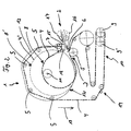
- the device 1 shows a device for producing a wound from a non-woven fabric for the thermal and acoustic insulation of buildings, in particular of mineral fibers, preferably made of rock wool and / or glass wool.
- the device has a conveying device 2 which conveys the nonwoven fabric into a winding station 1.
- the winding station 1 has a deflection device 3, which receives an incoming into the winding station 1 end of the fiber web and in Direction of the incoming nonwoven fabric deflects, wherein the deflection device 3 has a guide element in the form of a belt 4, which rotates over rollers 5 and rests during a winding operation on an outer circumferential surface of the roll, wherein a first roller 5 in the region of an inlet 6 of the nonwoven fabric in the Winding station 1 is arranged.
- the first roller 5 opposite a second roller 7 is arranged. Between the first roller 5 and the second roller 7, the deflection device 3 is formed, in which the band 4 is formed before the inlet of the nonwoven fabric as a loop 8, which increases during the winding process according to an increase in volume of the coil. Reference is made in this regard to FIG. 2, which will be described below.
- the belt 4 passes over a tension roller 9, which is part of a tensioning device 10, and is arranged to be movable in the tensioning device 10 parallel to the course of the belt 4.
- the rollers 5 and the roller 7 of the winding station 1 are radially arranged around a limited in its center 11 rotatably mounted carrier 12, wherein the distance between the center 11 and the rollers 5, 7 corresponds to at least half the maximum diameter of the roll of the nonwoven fabric ,
- the carrier 12 consists of two spaced-apart discs 13, of which only one disc 13 is shown in Figure 1 and between which the rollers 5 and 7 extend.
- the rollers 5 and 7 are rotatably arranged between the discs 13 of the carrier 12, wherein the rollers 5 are arranged in total above the inlet 6 and lying below the inlet 6 region of the carrier 12 is free of rollers 5 and 7 respectively. It can also be seen that the first roller 5 of the deflection device 3 is arranged outside the carrier 12 in a stationary manner.
- the device further comprises a braking device 14 with which the belt 4 can be reduced or stopped in its rotational speed.
- the brake device 14 is connected upstream of the tensioning device 10.
- a slide rail 15 is additionally arranged above the first roller 5 and in the region of the second roller 7.
- the slide rail 15 serves as a guide element of the introduction of the nonwoven fabric not shown, which is conveyed via the conveyor 2 in the region of the inlet 6, wherein the conveyor 2 comprises a first lower conveyor belt 16 and a second upper conveyor belt 17, which are aligned to each other and in a region immediately in front of the inlet 6 parallel to each other.
- the lower conveyor belt 16 extends into a region below the slide rail 15 between the roller 7 arranged on the carrier 12 and the second roller 5 arranged outside the carrier 12 and forming the deflection device 3.
- the nonwoven fabric not illustrated is thus transferred via the lower conveyor belt 16 guided in the immediate region of the inlet 6, wherein the nonwoven fabric between the upper conveyor belt 17 and the lower conveyor belt 16 is compressed and introduced in the compressed state between the slide rail 15 and the lower conveyor belt 16 in the inlet 6.
- the slide rail 15 is disposed below the upper roller 7 of the deflection device 3 and rotatably secured to the carrier 12.
- the band 4 is guided between the slide rail 15 and the roller 7 of the deflection device 3.
- the slide rail 15 is made of light metal, for example aluminum and has a surface 18 with a low coefficient of friction.
- the belt 4 is driven via an unillustrated drive from an electric motor and a flanged gear, wherein the rotational speed of the belt 4 are varied via a control of the drive motor can.
- the device is shown in a position immediately before receiving a fiber web, not shown in the winding station 1.
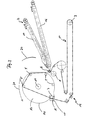
- FIG. 2 shows the winding station 1 in a position in which the tensioning roller 9 or 9 'has been moved back such that the loop 8 or 8' of the belt 4 or 4 'corresponds to an increase in volume of the winding within the winding station 1 has increased.
- FIG. 2 shows that a winding of a fiber fleece arranged in the loop 8 or 8 'is looped around the band 4 or 4' approximately over the entire outer circumferential surface of the roll. Consequently, during the winding process in the winding station 1, the reel is kept constant at a constant compression pressure, which, however, is variable via the tension pulley 9 or 9 '.
- FIG. 3 shows the device according to FIG. 1 in a position immediately after the ejection of a finished roll of a fiber fleece from the winding station 1.
- a guide device 20 is shown, which serves to guide the roll to be ejected from the winding station 1.
- the carrier 12 is rotated counterclockwise in the direction of an arrow 21 with respect to its position in Figure 1 and the tension roller 9 is moved to a position within the clamping device 10, in which the band 4 is maximally tensioned, wherein the loop 8 is stretched so that the winding, not shown, is ejected from the loop 8.
- the carrier 12 is rotated back into its starting position shown in FIG. 1, wherein the loop 8 forms in the region of the inlet 6 in order to start a new winding process.
- the band 4 assumes in the actual winding station 1 different shapes, resulting in different angles of wrap and tape lengths, while at the same time via a variable voltage of the belt 4 corresponding pressure and shear forces are exerted on the non-woven fabric to be wound.
- a variable rotational speed of the belt 4 By a variable rotational speed of the belt 4, the rotational speed of the coil and thus the specific power of the winding station 1 is varied in total.
- the distance between the two conveyor belts 16, 17 from each other is variable depending on the thickness of the nonwoven fabric and the degree of compression.
- the ends of the two pressure-transmitting conveyor belts 16, 17 are designed such that they lead far into the loop 8.
- the arranged below the upper roller 7 slide rail 15 is an extension of the upper pressure-transmitting conveyor belt 17.
- Their sliding surface 18 is preferably slightly obliquely aligned parallel to the plane of the lower conveyor belt 16.
- the end of the sliding surface 18 is rounded at the top, which facilitates the guiding of the belt 4 and the deflection of the incoming nonwoven fabric very much.
- the sliding surface 18 is relatively short so that the braking effect on the upper surface of the nonwoven fabric can be disregarded and in particular does not cause large tensile stresses in the nonwoven fabric.
- the front part of the slide rail 15 and the rear upper run of the upper conveyor belt 17 are designed so that the upper roller 7 together with the slide rail 15 can be moved past the conveyor belt 17.
- the small additional weight of the slide rail 15 requires neither a reinforcement of the construction nor the drive.
- a tension-resistant web is introduced between the end of the lower pressure-transmitting conveyor belt 16 and the lower introduction roller 5, which holds the high non-woven fabric under high internal tension.
- This tension-resistant web secures the shape of the roll, protects the fiber fleece and simultaneously serves the optical design of a packaging unit.
- the tension-resistant web is formed either as a banderole or as an envelope with open end faces.
- the tensile web consists of a plastic film, for example of a polyethylene film.
- the upper rollers 5 are pivoted together with the upper insertion roller 7 and the slide rail 15 about the central axes 11 in the counterclockwise direction, while the band 4 is stretched by moving out of the tension roller 9 in the widest position.
- a guide device 20 outlined here prevents the winding from being thrown off in the direction of the conveyor belts 16, 17.
- the tensioning device 10 can be moved in a short time in order to set a tension matched to the thickness, structure and other relevant properties of the fiber fleece as well as possibly a different amount of compression over the length of the fiber fleece or the circumference of the roll.
- the speed of the belt 4 can be changed in order, for example, to allow a rearrangement of structural elements within the fiber fleece during the winding process.
- the control of the individual processes, which form the winding process from the introduction of the fiber web into the conveyor 2 up to the ejection can therefore be extremely shortened and can even take place in parallel, so that optimally tuned, greatly shortened winding cycles are achieved on the sensitive nonwoven fabrics. This naturally leads to a substantial increase in the power capacity of the winding device.
Landscapes
- Engineering & Computer Science (AREA)
- Mechanical Engineering (AREA)
- Nonwoven Fabrics (AREA)
Priority Applications (1)
| Application Number | Priority Date | Filing Date | Title |
|---|---|---|---|
| EP05021703A EP1645532A1 (fr) | 2004-10-09 | 2005-10-05 | Procédé et dispositif de fabrication d'un enroulement de matériau non-tissée |
Applications Claiming Priority (5)
| Application Number | Priority Date | Filing Date | Title |
|---|---|---|---|
| DE102004049370 | 2004-10-09 | ||
| EP05020563 | 2005-09-21 | ||
| DE102005045162 | 2005-09-21 | ||
| DE200510047851 DE102005047851A1 (de) | 2004-10-09 | 2005-10-05 | Verfahren und Vorrichtung zur Herstellung eines Wickels aus einem Faservlies |
| EP05021703A EP1645532A1 (fr) | 2004-10-09 | 2005-10-05 | Procédé et dispositif de fabrication d'un enroulement de matériau non-tissée |
Publications (1)
| Publication Number | Publication Date |
|---|---|
| EP1645532A1 true EP1645532A1 (fr) | 2006-04-12 |
Family
ID=35546167
Family Applications (1)
| Application Number | Title | Priority Date | Filing Date |
|---|---|---|---|
| EP05021703A Withdrawn EP1645532A1 (fr) | 2004-10-09 | 2005-10-05 | Procédé et dispositif de fabrication d'un enroulement de matériau non-tissée |
Country Status (1)
| Country | Link |
|---|---|
| EP (1) | EP1645532A1 (fr) |
Citations (6)
| Publication number | Priority date | Publication date | Assignee | Title |
|---|---|---|---|---|
| US3964232A (en) | 1973-10-04 | 1976-06-22 | Johns-Manville Corporation | Method of packaging fibrous mat structure |
| US4114530A (en) * | 1977-06-23 | 1978-09-19 | Owens-Corning Fiberglas Corporation | Apparatus for packaging compressible strips |
| US4602471A (en) * | 1985-05-28 | 1986-07-29 | Owens-Corning Fiberglas Corporation | Roll-up method and apparatus for mineral fiber pack |
| DE3612587A1 (de) | 1985-04-30 | 1986-11-06 | VEB Plastmaschinenwerk Wiehe, DDR 4736 Wiehe | Vorrichtung zum schwenken der spritzeinheit einer spritzgiessmaschine |
| US5425512A (en) * | 1992-01-07 | 1995-06-20 | Isover Saint Gobain | Roll of compressed fibrous mat, method and device for obtaining it |
| DE19923352A1 (de) * | 1999-02-03 | 2000-08-10 | Rockwool Mineralwolle | Vorrichtung zum Aufwickeln eines Faservlieses |
-
2005
- 2005-10-05 EP EP05021703A patent/EP1645532A1/fr not_active Withdrawn
Patent Citations (7)
| Publication number | Priority date | Publication date | Assignee | Title |
|---|---|---|---|---|
| US3964232A (en) | 1973-10-04 | 1976-06-22 | Johns-Manville Corporation | Method of packaging fibrous mat structure |
| US4114530A (en) * | 1977-06-23 | 1978-09-19 | Owens-Corning Fiberglas Corporation | Apparatus for packaging compressible strips |
| DE3612587A1 (de) | 1985-04-30 | 1986-11-06 | VEB Plastmaschinenwerk Wiehe, DDR 4736 Wiehe | Vorrichtung zum schwenken der spritzeinheit einer spritzgiessmaschine |
| US4602471A (en) * | 1985-05-28 | 1986-07-29 | Owens-Corning Fiberglas Corporation | Roll-up method and apparatus for mineral fiber pack |
| US5425512A (en) * | 1992-01-07 | 1995-06-20 | Isover Saint Gobain | Roll of compressed fibrous mat, method and device for obtaining it |
| DE19923352A1 (de) * | 1999-02-03 | 2000-08-10 | Rockwool Mineralwolle | Vorrichtung zum Aufwickeln eines Faservlieses |
| DE19923352C2 (de) | 1999-02-03 | 2002-08-01 | Rockwool Mineralwolle | Vorrichtung zum Aufwickeln eines Faservlieses |
Similar Documents
| Publication | Publication Date | Title |
|---|---|---|
| EP0277500B1 (fr) | Procédé pour la fabrication en continu d'une feuille de matériau fibreux isolant, et appareil pour exécuter ce procédé | |
| DE69302101T2 (de) | Verfahren und Vorrichtung zum Komprimieren einer Rolle aus Fasermatte | |
| DE69708613T2 (de) | Verfahren und vorrichtung zur herstellung von einer mineralfaserplatte | |
| DE102008057463A1 (de) | Feder aus einem Faserverbundwerkstoff sowie Verfahren und Vorrichtung zur Herstellung derselben | |
| DE102019113067B3 (de) | Verfahren zur Herstellung eines flexibel formbaren Wabenkerns, Verwendung des Wabenkerns sowie Vorrichtung zur Durchführung des Verfahrens | |
| DE2307577B2 (de) | Verfahren zum herstellen von ebenen mineralwollplatten sowie anlage zur durchfuehrung des verfahrens | |
| EP1708876B1 (fr) | Procede de fabrication d'une bande de materiau isolant a partir de fibres minerales et bande de materiau isolant ainsi obtenue | |
| DE2308696C3 (de) | Einrichtung zur kontinuierlichen Herstellung von Spanplatten, Faserplatten u.dgl | |
| DE4001835A1 (de) | Verfahren und anlage zur herstellung von sandwich-elementen | |
| EP1026302B1 (fr) | Dispositif pour enrouler une bande non-tissée | |
| EP1645532A1 (fr) | Procédé et dispositif de fabrication d'un enroulement de matériau non-tissée | |
| EP1026301B1 (fr) | Procédé et dispositif de fabrication d'une nappe pour l'isolation | |
| DE2856506A1 (de) | Verfahren und vorrichtung zur herstellung einer verstaerkten formmasse in bahnform | |
| EP1097335A1 (fr) | Procede de production d'elements d'isolation de tuyaux et element d'isolation de tuyaux | |
| DE102005047851A1 (de) | Verfahren und Vorrichtung zur Herstellung eines Wickels aus einem Faservlies | |
| EP1561847B1 (fr) | Procédé et dispositif pour la fabrication de matériaux isolants en feuilles ou plaques à base de fibres minérales | |
| DE2124139C3 (de) | Verfahren zur Herstellung von Schichtstoffen und Vorrichtung zur Durchführung des Verfahrens | |
| DE19923352C2 (de) | Vorrichtung zum Aufwickeln eines Faservlieses | |
| CH692114A5 (de) | Vorrichtung und Verfahren zur Herstellung einer Mineralfaserplatte. | |
| EP1390262B1 (fr) | Procede de realisation d'une unite d'emballage et/ou de transport pour materiaux isolants en forme de plaques constitues de fibres minerales, unite d'emballage et/ou de transport, et plaque de materiau isolant | |
| EP1559845A1 (fr) | Procédé de fabrication d' une nappe isolante en fibres minérales et nappe isolante | |
| DE29923197U1 (de) | Vorrichtung zum Aufwickeln eines Faservlieses | |
| DE102004049063B4 (de) | Verfahren zur Herstellung eines Dämmstoffprodukts und Dämmstoffprodukt | |
| DE2245523A1 (de) | Vorrichtung zum ausformen von fasermatten, vorzugsweise aus mineralfasern | |
| DE29923378U1 (de) | Vorrichtung zum Aufwickeln eines Faservlieses |
Legal Events
| Date | Code | Title | Description |
|---|---|---|---|
| PUAI | Public reference made under article 153(3) epc to a published international application that has entered the european phase |
Free format text: ORIGINAL CODE: 0009012 |
|
| AK | Designated contracting states |
Kind code of ref document: A1 Designated state(s): AT BE BG CH CY CZ DE DK EE ES FI FR GB GR HU IE IS IT LI LT LU LV MC NL PL PT RO SE SI SK TR |
|
| AX | Request for extension of the european patent |
Extension state: AL BA HR MK YU |
|
| AKX | Designation fees paid | ||
| STAA | Information on the status of an ep patent application or granted ep patent |
Free format text: STATUS: THE APPLICATION IS DEEMED TO BE WITHDRAWN |
|
| 18D | Application deemed to be withdrawn |
Effective date: 20061013 |
|
| REG | Reference to a national code |
Ref country code: DE Ref legal event code: 8566 |