EP1645692A1 - Elektromechanische Spülvorrichtung - Google Patents
Elektromechanische Spülvorrichtung Download PDFInfo
- Publication number
- EP1645692A1 EP1645692A1 EP05021970A EP05021970A EP1645692A1 EP 1645692 A1 EP1645692 A1 EP 1645692A1 EP 05021970 A EP05021970 A EP 05021970A EP 05021970 A EP05021970 A EP 05021970A EP 1645692 A1 EP1645692 A1 EP 1645692A1
- Authority
- EP
- European Patent Office
- Prior art keywords
- flush
- motor
- drive
- valve
- rotate
- Prior art date
- Legal status (The legal status is an assumption and is not a legal conclusion. Google has not performed a legal analysis and makes no representation as to the accuracy of the status listed.)
- Withdrawn
Links
Images


Classifications
-
- B—PERFORMING OPERATIONS; TRANSPORTING
- B60—VEHICLES IN GENERAL
- B60R—VEHICLES, VEHICLE FITTINGS, OR VEHICLE PARTS, NOT OTHERWISE PROVIDED FOR
- B60R15/00—Arrangements or adaptations of sanitation devices
- B60R15/04—Toilet facilities
-
- B—PERFORMING OPERATIONS; TRANSPORTING
- B63—SHIPS OR OTHER WATERBORNE VESSELS; RELATED EQUIPMENT
- B63B—SHIPS OR OTHER WATERBORNE VESSELS; EQUIPMENT FOR SHIPPING
- B63B29/00—Accommodation for crew or passengers not otherwise provided for
- B63B29/02—Cabins or other living spaces; Construction or arrangement thereof
- B63B29/14—Closet or like flushing arrangements; Washing or bathing facilities peculiar to ships
-
- E—FIXED CONSTRUCTIONS
- E03—WATER SUPPLY; SEWERAGE
- E03D—WATER-CLOSETS OR URINALS WITH FLUSHING DEVICES; FLUSHING VALVES THEREFOR
- E03D1/00—Water flushing devices with cisterns ; Setting up a range of flushing devices or water-closets; Combinations of several flushing devices
- E03D1/30—Valves for high or low level cisterns; Their arrangement ; Flushing mechanisms in the cistern, optionally with provisions for a pre-or a post- flushing and for cutting off the flushing mechanism in case of leakage
- E03D1/34—Flushing valves for outlets; Arrangement of outlet valves
-
- E—FIXED CONSTRUCTIONS
- E03—WATER SUPPLY; SEWERAGE
- E03D—WATER-CLOSETS OR URINALS WITH FLUSHING DEVICES; FLUSHING VALVES THEREFOR
- E03D5/00—Special constructions of flushing devices, e.g. closed flushing system
- E03D5/10—Special constructions of flushing devices, e.g. closed flushing system operated electrically, e.g. by a photo-cell; also combined with devices for opening or closing shutters in the bowl outlet and/or with devices for raising/or lowering seat and cover and/or for swiveling the bowl
Definitions
- the present invention relates to toilets. More particularly, the present invention relates to a toilet and flush mechanism that is suitable for a boat, recreational vehicle (RV), bus or the like.
- RV recreational vehicle
- the toilet according to the present invention may either be of the gravity drop through type or of the vacuum type (such as generally shown in U.S. Patent No. 5,621,924, the disclosure of which is hereby incorporated by reference).
- a flush mechanism for a toilet comprising, a rotatable flush valve, a drive mechanism operatively connected to the flush valve, a motor to move the drive mechanism, and a spring operatively connected to the drive mechanism to bias the drive mechanism in a direction so as to rotate the flush valve.
- a flush mechanism for a toilet comprising, a frame, a support structure operatively connected to the frame a rotatable flush valve positioned in the support structure, a rotor shaft operatively connected to the flush valve, a rotor cam coupled to the rotor shaft, a drive arm operatively connected to the rotor cam at a first end and to the frame at a second end, a motor to move the drive arm, and a spring opcrativety connected to the frame at one end and to the rotor cam at the opposite end to bias the drive arm in a direction so as to rotate the flush valve.
- a method of flushing a toilet comprising the steps of activating an actuating mechanism, activating a flush/add water switch, energizing a motor and a water inlet valve, disengaging a motor arm from a drive ann slot, biasing a drive mechanism in a direction so as to rotate a flush valve, and re-engaging the motor arm in the drive slot so as to rotate the flush valve to in an opposite direction.
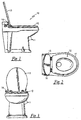
- FIGURE 1 is a side view of an exemplary toilet according to the invention.
- FIGURE 2 is a top view of the toilet shown in FIGURE 1.
- FIGURE 3 is a front view of the toilet shown in FIGURE 1.
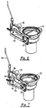
- FIGURE 4 is a perspective view of one embodiment of the flush mechanism in a closed state for the toilet of FIGURES 1-3.
- FIGURE 5 is a perspective view of the flush mechanism ofFIGURE 4 in an open state.
- FIGURE 6 is a perspective view of the flush mechanism of FIGURE 4 in a closing state.
- FIGURE 7 is a perspective view of the flush mechanism of FIGURE 4 in an emergency use state.
- FIGURE 8 shows a timing chart showing the operation of the toilet in accordance with the present invention.
- FIGURES 1-3 show a toilet 10 (either vacuum or drop through) in accordance with the present invention having a substantially all china one-piece combination bowl and base 11, with a conventional toilet seat 12 and cover 13.
- the toilet 10 In exterior appearance, the toilet 10 generally resembles conventional toilets in both size and material found in homes, businesses and the like.
- the toilet 10 includes an actuating mechanism 16 that activates either a flush mode or an add water mode.
- the actuating mechanism 16 can be any type of actuating mechanism known in the art such as, but not limited to, a foot pedal, a lever, a pushbutton, a rocker switch, etc.
- the actuating mechanism can be located on the toilet, as shown in FIGURES 1-3, or it can be located near the toilet, for example, on a wall, a cabinet, a counter, etc. located near the toilet.
- FIGURE 4 shows a flush mechanism 20 in a closed state in accordance with the present invention.
- the flush mechanism 20 includes a frame 21 and a flush valve 22, which is positioned in a ring-like cylindrical-support structure 24.
- the support structure 24 is connected to one end of the frame 21 as shown in FIGURE 4 and provides support for the flush mechanism 20.
- the support structure 24 can be connected to the frame by any means known in the art such as with screws, rivets, straps, etc.
- the flush valve 22 is coupled to a rotor cam 26 via a rotor shaft 28.
- a motor 30 rotates the rotor cam 26, which in turn rotates the rotor shaft 28, which rotates the flush valve 22.
- the motor 30 further includes a motor arm 38 to move a drive mechanism such as a drive arm 32 to thereby rotate the rotor cam 26.
- a first end 33 of the drive arm 32 is connected to a cam pin 34.
- the cam pin 34 is connected to the rotor cam 26 and extends in an outward direction from the rotor cam 26.
- a second end 35 of the drive arm 32 is connected to the frame 21 at an end opposite the support structure 24-
- the second end 35 of the drive arm 32 further includes a drive arm slot 36, which receives the motor arm 38.
- a spring 40 is attached to the frame 21 at one end and to the rotor cam 26 at the opposite end. During operation of the flush mechanism 20, the spring 40 biases the drive arm 32 in a direction such that the flush valve 22 rotates to an open position.
- the motor arm 38 engages the drive arm slot 36 thereby preventing the spring 40 from biasing the drive arm 32 to open the flush valve 22.
- the flush mechanism 20 In the flush mode the user activates the flush mechanism 20 by activating the actuating mechanism 16. Once the flush mechanism 20 is activated a flush/add water switch is momentarily activated, for example for 0.5 seconds, thereby initially energizing the motor 30 and a water inlet valve.
- the motor 30 begins to rotate the motor arm 38 in such a manner that the motor arm 38 is disengaged from the drive arm slot 36.
- the drive arm 32 is released and the spring 40 begins to rotate the rotor cam 26 which in turn biases the drive arm 32 in the direction indicated by the arrow 42.
- the rotor cam 26 rotates, which rotates the rotor shaft 28 thereby rotating the flush valve 22 to an open position as shown in FIGURE 5.
- the motor arm 3 8 re-engages the drive arm slot 36 thereby moving the drive arm 32 in a direction opposite that of the arrow 42.
- the rotor cam 26 rotates in a direction such that the flush valve 22 begins to close as shown in FIGURE 6.
- the present invention is not limited to the embodiment described above or below and shown in the FIGURES.
- the present invention can operate in a manner where the spring 40 biases the drive arm 32 in a direction such that the flush valve 22 rotates to a closed position.
- the motor 30, instead of closing the flush valve 22, can move the drive arm 32 in a direction such that the flush valve 22 rotates to an open position.
- the flush/add water switch is momentarily activated, for example for 0.5 seconds, thereby initially energizing the motor 30 and the water inlet valve.
- the cam switch 44 controls the motor 30 and the water inlet valve thereby controlling the duration of the flush cycle.
- the flush valve 22 will remain open for a predetermined period of time which is dependent on the rotation speed of the motor 30.
- a power boost bar 46 may be provided on the drive arm 32 to provide additional force to rotate the flush valve 22, Referring to the embodiment shown in the FIGURES 4-7, as the motor arm 38 rotates a projection 39 on the motor arm 38 contacts the power boost bar 46 and forces it in the direction indicated by the arrow 42, thus, providing additional force to open the flush valve 22.
- an emergency flush rod 50 is provided to provide a means to operate the toilet 10 in the event that electrical power is lost or the motor 30 or actuating mechanism 16 are not operable.
- the flush rod 50 is mechanically attached to the motor arm 38 such that when the user depresses the flush rod 50 the motor arm 38 is disengaged from the drive arm slot 36. Once motor arm 38 is disengaged the spring 40 biases the drive arm 32 in a direction indicated by the arrow 42 thus opening the flush valve 22 as described above.
- the flush valve 22 will remain open until power is restored to the toilet 10. Once power is restored the cam switch 44 will be activated and the flush cycle will complete its cycle as described above.
- a return spring is provided to return the flush rod 50 to its normal position after it has been released.
- FIGURE 8 shows a timing chart for operating the toilet in the flush mode.
- the amount of time required for the toilet to compete one flush cycle can be any time period required to provide an adequate flush.
- the cycle represented in FIGURE 8 has a timing cycle of 5 seconds.
- the water valve When the user activates the actuating mechanism 16 in the add water mode the water valve is energized to allow water to enter the bowl.
- the amount of water permitted in the bowl can be controlled manually or by water level switches.
- the flush mechanism 20 further includes an optional control feature that prevents the toilet from flushing unless the vacuum is at a sufficient level to provide an adequate flushing force.
Landscapes
- Engineering & Computer Science (AREA)
- Public Health (AREA)
- Health & Medical Sciences (AREA)
- Life Sciences & Earth Sciences (AREA)
- Mechanical Engineering (AREA)
- Hydrology & Water Resources (AREA)
- Water Supply & Treatment (AREA)
- General Health & Medical Sciences (AREA)
- Epidemiology (AREA)
- Aviation & Aerospace Engineering (AREA)
- Chemical & Material Sciences (AREA)
- Combustion & Propulsion (AREA)
- Ocean & Marine Engineering (AREA)
- Sanitary Device For Flush Toilet (AREA)
Applications Claiming Priority (1)
| Application Number | Priority Date | Filing Date | Title |
|---|---|---|---|
| US61710304P | 2004-10-08 | 2004-10-08 |
Publications (1)
| Publication Number | Publication Date |
|---|---|
| EP1645692A1 true EP1645692A1 (de) | 2006-04-12 |
Family
ID=35610005
Family Applications (1)
| Application Number | Title | Priority Date | Filing Date |
|---|---|---|---|
| EP05021970A Withdrawn EP1645692A1 (de) | 2004-10-08 | 2005-10-07 | Elektromechanische Spülvorrichtung |
Country Status (2)
| Country | Link |
|---|---|
| US (1) | US20060075546A1 (de) |
| EP (1) | EP1645692A1 (de) |
Cited By (4)
| Publication number | Priority date | Publication date | Assignee | Title |
|---|---|---|---|---|
| WO2009092204A1 (zh) * | 2007-12-27 | 2009-07-30 | Shanghai Kohler Electronics, Ltd. | 自动冲水驱动装置 |
| CN102713096A (zh) * | 2009-11-17 | 2012-10-03 | 科勒公司 | 带有冲水阀启动器的卫生洁具及校准冲水阀启动器的方法 |
| CN108612166A (zh) * | 2018-07-21 | 2018-10-02 | 华北理工大学 | 智能翻转式节水防臭蹲便器装置 |
| CN115404960A (zh) * | 2021-05-26 | 2022-11-29 | 深圳市恒致云科技有限公司 | 冲洗机构及卫浴设备 |
Families Citing this family (3)
| Publication number | Priority date | Publication date | Assignee | Title |
|---|---|---|---|---|
| RU2471929C1 (ru) * | 2008-10-03 | 2013-01-10 | Б/Е Аэроспейс, Инк. | Смывной клапан для вакуумной системы для отходов |
| US10208468B2 (en) | 2015-03-30 | 2019-02-19 | B/E Aerospace, Inc. | Maintenance mode for aircraft vacuum toilet |
| USD1112626S1 (en) | 2022-07-15 | 2026-02-10 | Zurn Water, Llc | Flush valve |
Citations (3)
| Publication number | Priority date | Publication date | Assignee | Title |
|---|---|---|---|---|
| US5621924A (en) | 1995-06-07 | 1997-04-22 | Sealand Ttechnology, Inc. | Vacuum tank construction for a vacuum toilet assembly |
| WO2002044483A2 (en) * | 2000-11-28 | 2002-06-06 | Sealand Technology, Inc. | Toilet and method of operation |
| WO2004029491A1 (en) * | 2002-09-25 | 2004-04-08 | Sung-Hyun Cho | Water saving apparatus with function of deodorization |
Family Cites Families (10)
| Publication number | Priority date | Publication date | Assignee | Title |
|---|---|---|---|---|
| US3204484A (en) * | 1962-11-16 | 1965-09-07 | Calco Mfg Company | Spider drive rotary valve actuating mechanism |
| US3214772A (en) * | 1964-10-15 | 1965-11-02 | Western Pottery Co Inc | Hopper for mechanical seal toilets |
| US3965492A (en) * | 1974-08-12 | 1976-06-29 | Hendricks Victor P | Electric flushing toilet bowl |
| US4270849A (en) * | 1979-04-12 | 1981-06-02 | Kalbfleisch Adolphe W | Rotary valve actuator construction |
| US4918764A (en) * | 1988-06-13 | 1990-04-24 | Microphor, Inc. | Electrically operated toilet |
| US5680879A (en) * | 1994-09-12 | 1997-10-28 | Technical Concepts, Inc. | Automatic flush valve actuation apparatus for replacing manual flush handles |
| AU721854B2 (en) * | 1996-07-11 | 2000-07-13 | Medtronic, Inc. | Minimally invasive implantable device for monitoring physiologic events |
| US5971005A (en) * | 1998-03-25 | 1999-10-26 | Sealand Technology, Inc. | Vacuum adaptor for recreation vehicle toilet system with sliding cassette holding tank |
| US6200265B1 (en) * | 1999-04-16 | 2001-03-13 | Medtronic, Inc. | Peripheral memory patch and access method for use with an implantable medical device |
| US6589187B1 (en) * | 2000-12-08 | 2003-07-08 | Medtronic, Inc. | Prioritized dynamic memory allocation of arrhythmia episode detail collection |
-
2005
- 2005-10-07 EP EP05021970A patent/EP1645692A1/de not_active Withdrawn
- 2005-10-07 US US11/246,846 patent/US20060075546A1/en not_active Abandoned
Patent Citations (3)
| Publication number | Priority date | Publication date | Assignee | Title |
|---|---|---|---|---|
| US5621924A (en) | 1995-06-07 | 1997-04-22 | Sealand Ttechnology, Inc. | Vacuum tank construction for a vacuum toilet assembly |
| WO2002044483A2 (en) * | 2000-11-28 | 2002-06-06 | Sealand Technology, Inc. | Toilet and method of operation |
| WO2004029491A1 (en) * | 2002-09-25 | 2004-04-08 | Sung-Hyun Cho | Water saving apparatus with function of deodorization |
Cited By (8)
| Publication number | Priority date | Publication date | Assignee | Title |
|---|---|---|---|---|
| WO2009092204A1 (zh) * | 2007-12-27 | 2009-07-30 | Shanghai Kohler Electronics, Ltd. | 自动冲水驱动装置 |
| CN102713096A (zh) * | 2009-11-17 | 2012-10-03 | 科勒公司 | 带有冲水阀启动器的卫生洁具及校准冲水阀启动器的方法 |
| US8555428B2 (en) | 2009-11-17 | 2013-10-15 | Kohler Co. | Plumbing fixture with flush valve actuator and methods of calibrating same |
| CN102713096B (zh) * | 2009-11-17 | 2014-07-09 | 科勒公司 | 带有冲水阀启动器的卫生洁具及校准冲水阀启动器的方法 |
| US9611633B2 (en) | 2009-11-17 | 2017-04-04 | Kohler Co. | Plumbing fixture with flush valve actuator and methods for calibrating same |
| CN108612166A (zh) * | 2018-07-21 | 2018-10-02 | 华北理工大学 | 智能翻转式节水防臭蹲便器装置 |
| CN108612166B (zh) * | 2018-07-21 | 2024-04-02 | 华北理工大学 | 智能翻转式节水防臭蹲便器装置 |
| CN115404960A (zh) * | 2021-05-26 | 2022-11-29 | 深圳市恒致云科技有限公司 | 冲洗机构及卫浴设备 |
Also Published As
| Publication number | Publication date |
|---|---|
| US20060075546A1 (en) | 2006-04-13 |
Similar Documents
| Publication | Publication Date | Title |
|---|---|---|
| EP2060684B1 (de) | Toilette mit Steuerung zum Steuern von Spülventil und Ablaufventil | |
| US20050077492A1 (en) | Automatic flush actuation apparatus | |
| US3504385A (en) | Toilet seat lifter | |
| US6038708A (en) | Automatic toilet seat with protective covering | |
| EP1645692A1 (de) | Elektromechanische Spülvorrichtung | |
| FR2471453A2 (fr) | Bloc sanitaire | |
| US4831670A (en) | Automatic flushing apparatus for toilets | |
| US8152135B2 (en) | Automatic flush actuation apparatus | |
| CA2595670C (en) | Automatic flush actuation apparatus | |
| US7415737B2 (en) | Automatic flusher for tank-type toilet | |
| CN113597493A (zh) | 清洗水箱装置以及具备该清洗水箱装置的水洗便器装置 | |
| US3056142A (en) | Toilet flushing device | |
| CN104011304A (zh) | 马桶自动冲洗装置 | |
| JP2004129835A (ja) | 自動便蓋閉止装置 | |
| GB2302623A (en) | Electric motor drive device for operating a lever | |
| KR102911399B1 (ko) | 변기의 자동 물내림 장치 | |
| PL349803A1 (en) | Quick-discharge valve control device for lavatory bowl flushing cisterns | |
| JP2741932B2 (ja) | 便器水洗装置 | |
| JPH03100239A (ja) | 水洗便器用排水装置 | |
| JPS6030736A (ja) | 排気装置を備えた水洗トイレ | |
| JPH0711683A (ja) | 便器水洗装置 | |
| JPH07100081A (ja) | 便 器 | |
| JP2025145543A (ja) | 洗浄水タンク装置 | |
| JP2007050068A (ja) | 便座開閉システム | |
| JPH03103541A (ja) | 水洗便器用排水装置 |
Legal Events
| Date | Code | Title | Description |
|---|---|---|---|
| PUAI | Public reference made under article 153(3) epc to a published international application that has entered the european phase |
Free format text: ORIGINAL CODE: 0009012 |
|
| AK | Designated contracting states |
Kind code of ref document: A1 Designated state(s): AT BE BG CH CY CZ DE DK EE ES FI FR GB GR HU IE IS IT LI LT LU LV MC NL PL PT RO SE SI SK TR |
|
| AX | Request for extension of the european patent |
Extension state: AL BA HR MK YU |
|
| 17P | Request for examination filed |
Effective date: 20060323 |
|
| AKX | Designation fees paid |
Designated state(s): AT BE BG CH CY CZ DE DK EE ES FI FR GB GR HU IE IS IT LI LT LU LV MC NL PL PT RO SE SI SK TR |
|
| RAP1 | Party data changed (applicant data changed or rights of an application transferred) |
Owner name: DOMETIC CORPORATION |
|
| STAA | Information on the status of an ep patent application or granted ep patent |
Free format text: STATUS: THE APPLICATION IS DEEMED TO BE WITHDRAWN |
|
| 18D | Application deemed to be withdrawn |
Effective date: 20110531 |