EP1645698A1 - Une structure de toit - Google Patents
Une structure de toit Download PDFInfo
- Publication number
- EP1645698A1 EP1645698A1 EP04077722A EP04077722A EP1645698A1 EP 1645698 A1 EP1645698 A1 EP 1645698A1 EP 04077722 A EP04077722 A EP 04077722A EP 04077722 A EP04077722 A EP 04077722A EP 1645698 A1 EP1645698 A1 EP 1645698A1
- Authority
- EP
- European Patent Office
- Prior art keywords
- roof structure
- profile
- structure according
- anchoring
- insulation panel
- Prior art date
- Legal status (The legal status is an assumption and is not a legal conclusion. Google has not performed a legal analysis and makes no representation as to the accuracy of the status listed.)
- Withdrawn
Links
- 238000004873 anchoring Methods 0.000 claims abstract description 86
- 238000009413 insulation Methods 0.000 claims abstract description 80
- 230000014759 maintenance of location Effects 0.000 claims abstract description 22
- 239000011810 insulating material Substances 0.000 claims abstract description 9
- 230000000284 resting effect Effects 0.000 claims abstract description 3
- 239000012774 insulation material Substances 0.000 claims description 16
- 238000010276 construction Methods 0.000 claims description 11
- 230000009977 dual effect Effects 0.000 claims description 10
- 239000002184 metal Substances 0.000 claims description 10
- 241000826860 Trapezium Species 0.000 claims description 8
- 239000000835 fiber Substances 0.000 claims description 5
- 239000011490 mineral wool Substances 0.000 claims description 3
- 239000011230 binding agent Substances 0.000 claims description 2
- 238000003754 machining Methods 0.000 abstract description 4
- 238000005452 bending Methods 0.000 description 4
- 238000000034 method Methods 0.000 description 3
- 230000004888 barrier function Effects 0.000 description 1
- 230000006835 compression Effects 0.000 description 1
- 238000007906 compression Methods 0.000 description 1
- 238000006073 displacement reaction Methods 0.000 description 1
- 238000009826 distribution Methods 0.000 description 1
- 238000005553 drilling Methods 0.000 description 1
- 239000006260 foam Substances 0.000 description 1
- 239000011888 foil Substances 0.000 description 1
- 239000011491 glass wool Substances 0.000 description 1
- 229910052500 inorganic mineral Inorganic materials 0.000 description 1
- 238000004519 manufacturing process Methods 0.000 description 1
- 239000011707 mineral Substances 0.000 description 1
- 230000000717 retained effect Effects 0.000 description 1
- 238000010008 shearing Methods 0.000 description 1
Images

Classifications
-
- E—FIXED CONSTRUCTIONS
- E04—BUILDING
- E04D—ROOF COVERINGS; SKY-LIGHTS; GUTTERS; ROOF-WORKING TOOLS
- E04D3/00—Roof covering by making use of flat or curved slabs or stiff sheets
- E04D3/36—Connecting; Fastening
- E04D3/3601—Connecting; Fastening of roof covering supported by the roof structure with interposition of a insulating layer
- E04D3/3602—The fastening means comprising elongated profiles installed in or on the insulation layer
-
- E—FIXED CONSTRUCTIONS
- E04—BUILDING
- E04D—ROOF COVERINGS; SKY-LIGHTS; GUTTERS; ROOF-WORKING TOOLS
- E04D13/00—Special arrangements or devices in connection with roof coverings; Protection against birds; Roof drainage ; Sky-lights
- E04D13/16—Insulating devices or arrangements in so far as the roof covering is concerned, e.g. characterised by the material or composition of the roof insulating material or its integration in the roof structure
- E04D13/1606—Insulation of the roof covering characterised by its integration in the roof structure
- E04D13/1643—Insulation of the roof covering characterised by its integration in the roof structure the roof structure being formed by load bearing corrugated sheets, e.g. profiled sheet metal roofs
- E04D13/165—Double skin roofs
Definitions
- the present invention relates to a roof structure with a fibrous insulating panel assembly, said roof structure including an insulation layer of fibrous insulating material, which is mounted onto a support structure by anchoring means including at least one of longitudinal anchoring profile on the outside of the insulating material layer for retaining the insulation layer and for supporting a top panel structure, which may be secured to said at least one profile, which are secured to the support structure through the insulation layer by connecting elements
- a roof structure of such kind is known from EP-A-0 685 612.
- the insulation material is put in place on the support structure of the roof.
- a U-shaped profile is then machined into the insulation material by a machining tool which is utilised on the roof.
- the insulation is typically a dual density product comprising a lower layer of mineral fibres with relative low density and an outer top layer with relatively high density.
- the top layer provides the insulation with a treading resistance as well as a distribution of pressure.
- the U-profile provides for the transfer of upwardly directed wind forces as well as transfer of shearing forces to the support structure via the anchoring screws.
- the top panel structure is fixedly secured to the U-profiles at a number of positions whereas the U-profile is fixedly secured to the support structure at other positions.
- the insulation panels may be separately fixed to the roof furring construction, i.e. the support structure, via the anchoring profiles extending across the insulation panels.
- the top panel structure may subsequently be mounted onto the anchoring profiles.
- the profiles stabilises the insulation panels before the top structure is mounted thereon.
- the profiles may be appropriately anchored to the support structure, such as a trapezium sheet panel to which the profiles are fixed to the high ridges of this supporting trapezium sheet panel.
- the anchoring profiles are fixed to the support structure at as many points as necessary in order to ensure a firm anchoring enabling the profiles to carry the load of the top structure.
- a drawback of this roof structure is that a machine tool must be utilised on the roof in order to machine a set of grooves for fitting the U-shaped anchoring profile in the top surface of the insulation. This machine must be lifted up on the roof and back down again after use. This is both time consuming and contributes to extra costs for building the under-roof structure.
- a sub-structure for a roof is known, where a simple metal strip is provided for fixing the insulation to the support structure.
- this fixation lacks any stiffness and does not contribute of absorbing any roof load, such as wind load suction or compression due to the weight of snow on the roof.
- a roof structure of the initially mentioned kind wherein said at least one anchoring profile comprises at least one profile retention portion having a resting surface, which rests on the outer surface of the insulation panel, and at least one longitudinally oriented inwardly protruding profile portion and that at least the outer portion of the insulation panel is having a low density, so that the inwardly protruding portion locally compress the insulation panel when the anchoring profile is mounted and thereby retaining the insulation panel in the roof structure.
- a roof structure with an anchoring profile may be provided where no machining of the upper surface of the insulation panel is required in order to mount the profiles in the insulation panel of the roof structure whilst providing a rigid insulation mounting in the roof structure.
- the anchoring profile is designed with an inwardly protruding longitudinal portion which is compressed into the insulation material, which at least on the outer side of the insulation structure has a relative low density, for instance between 50-100 kg/m 3 , preferably between 75-90 kg/m 3 .
- the anchoring profiles can be placed directly on the insulation panel surface and the protruding portion of the profile is pressed into the insulation and secured to the support structure by the connecting elements of the anchoring means.
- the insulation material may be of any suitable type, e.g. foam or fibrous insulation material, such as mineral wool, especially rock wool or glass wool. A fibrous insulation material is often preferred.
- the connecting elements are anchoring screws for securing the profiles to the support structure.
- the profile is preferably provided with apertures at a predetermined distance for receiving the anchoring screws.
- other suitable means of attachment may be used.
- the retention and protruding portions are integrally formed in the anchoring profile as a one-piece structure.
- the retention and protruding portions may be formed in separate sub-profiles, which are assembled to the anchoring profile.
- the anchoring profile may be formed in a metal sheet which is bend into a predetermined shape, where the metal sheet has a thickness of 0.75-1.75 mm, preferably approx. 1.2 mm.
- an suitable anchoring profile may be produced at relative low costs.
- the anchoring profile is symmetric along its longitudinal axis.
- the profile is prevented from tilting when mounted on the roof structure.
- the profile has a centrally disposed, inwardly protruding profile portion with a retention portion on each side thereof.
- the inwardly protruding portion consists of a base portion disposed generally parallel to the retention portions and two upright portions connecting the base portion with a retention portion on each side thereof. This geometric shape provides a profile with a good stiffness as well as being easy to mount, i.e. slightly compress the upper layer of the insulation.
- the base portion is provided with anchoring holes for the connecting elements.
- the connecting element may extend into the space inside the protruding profile portion if the roof structure is compressed, e.g. by walking on the roof structure during its construction. Accordingly, the two upright portions of the profile and the retention portions protect the anchoring screw from being damaged.
- the side edges of the profile are bend downwards in order to provide extra stiffness.
- the anchoring profile is a stackable profile.
- the profile With bending angles different than 90° between the upright portions and the base portion, the upright portions and the retention portions and the retention portions and the side edge portions, the profile becomes stackable.
- the profile has a central retention portion with inwardly protruding portions on each side thereof.
- the fibrous insulation panel is a dual-density fibrous insulation panel having a first layer having a relative low density facing outwards and a high-density layer inwards.
- the outermost layer is relatively easily compressible and the innermost layer of the insulation sufficiently stiff to withstand the roof load.
- the low-density layer in the dual density fibrous insulation panel is provided with a density between 50-100 kg/m 3 , preferably between 75-90 kg/m 3 .
- the high-density layer in the dual density fibrous insulation panel is preferably provided with a density of 50-150 kg/m 3 , preferably 90-120 kg/m 3 .
- the fibrous insulation panel has a uniform density of 60-150 kg/m 3 , preferably between 80-120 kg/m 3 .
- the easily compressible outer layer of the insulation may also be achieved by giving the outer layer a treatment, e.g. a mechanical treatment, making it more flexible or resilient. This could be the application of rollers compressing the outer layer in order to softening this, as described in WO 03/042445. Another method for providing a more flexible or softer outer layer could be to add a less amount of binder to the outer layer.
- a further method is to manipulate the fibre orientation, e.g. by having a fibre orientation in the top layer substantially parallel to the major surfaces of the insulation and in the lower layer having a fibre orientation substantially perpendicular to the major surface. The fibre orientation can be manipulated by different methods applied on both the primary web and the secondary web on the production line. This is described in further details in WO 97/36035.
- the compressible top layer by combining different insulation products. This may be two or more different insulation materials.
- the layer of fibrous insulating material comprises rectangular panels.
- Other shapes may also be used, e.g. a number of wedge-shaped panels, in particular cut-to-fall slabs.
- Elongated apertures may be provided in the profiles through which the anchoring screws are mounted.
- expansions of the anchoring profiles due to thermal impacts will not bend the anchoring elements, i.e. the screws.
- the anchoring screws are not weakened in strength, which in turn means that less screws are needed in order to provide the necessary anchoring force in order to achieve a good lifetime of the roof construction.
- By using a less amount of anchoring screws for securing the insulation to the support structure better acoustic properties and heat insulation properties are achieved, as the reduced number of anchoring points results in a reduction of noise and heat transfer points through the insulation layer.
- the elongated apertures may be provided as slits in the profile.
- the anchoring screws may open the slits at the point of actual mounting and penetrate through the slit and the insulation layer for being anchored to the support structure.
- the support structure may be a corrugated sheet, such as a trapezium sheet, a concrete panel section or a wooden construction.
- the top structure may be any kind of outer covering, such as roof panels, tiles, with or without extra insulation on top of the sub-roof structure according to the invention.
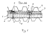
- a roof structure of the kind shown in fig. 1 is known in the art.
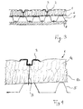
- Such double layer roof system comprises a support structure 5, such as a trapezium sheet mounted on a generally planar underlying wall or roof panel 8 (see fig. 3).
- a vapour barrier 6 may be positioned between the support structure 5 and the insulation material 1.
- a layer of insulation material 1 is positioned on the support structure 5 and retained in this position by anchoring means.
- These anchoring means includes anchoring profiles 2, which are positioned across the upper side of the insulation material 1 and secured to the underlying support structure 5 via a number of anchoring screws 3 extending through the insulation material 1.
- the support structure 5 may be a trapezium sheet, a corrugated metal sheet, a concrete wall section, a wooden support structure or any other suitable roof or wall panel structure.
- the insulation material 1 is preferably a dual-density type fibrous insulation panel where the upper layer of the panel is provided with a higher density than the lower.
- the anchoring profile 2 is U-shaped. The profile 2 is inserted into two machined grooves 9 in the insulation panel 1 preferably so that the high-density layer 14 is not perforated by the downwardly protruding wings of the profile 2.
- a top structure 4 is mounted onto the anchoring profiles 2.
- An intermediate sheet panel 7 may be provided between the profiles 2 and the top structure 4 which may be a sheet panel system, e.g. trapezium sheets or other top mounted structures, including e.g. solar panels or the like.
- the top structure 4 may be a foil or similar non-metallic covering which is secured to the profiles 3 in a suitable manner.
- the U-shaped anchoring profiles 2 are provided with a certain distance from each other. If an intermediate panel 7 is mounted on the profiles 2, the top structure 4 need not necessarily be fixed to the profiles 2 but may be fixed to the panel 7. This provides a great flexibility in the top structure mounting.
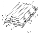
- the need for machining grooves for the anchoring profiles is not needed by a roof structure according to the invention, as the anchoring profile 2 is pressed into the upper side of the fibrous insulation layer 1.
- the anchoring profiles 2 are mounted to the support structure 5 by anchoring screws 3 which extend through the insulation material 1. Due to the shape of the anchoring profile 2, the profiles 2 are held in a predetermined position when mounted and fixate the insulation panels in their place.
- the elasticity of the fibrous insulation panel 1 provides a stabile roof structure as the profiles 2 are pressed outwards once they are mounted to the support structure 5 by the anchoring screws 3. This provides a stabile and sturdy roof structure, which serves as a base structure (sub-roof structure) for the outermost top structure 4, 7 of the roof.
- the fibrous insulation panel 1 is preferably a dual-density insulation panel where the top layer 1a has a low density and the bottom layer 1b has a high density.
- the low-density layer 1a preferably has a density between 50-100 kg/m 3 , most preferably, between 75-90 kg/m 3
- high-density layer 1b in the dual density fibrous insulation panel 1 is preferably provided with a density of 70-150 kg/m 3 , preferably 90-120 kg/m 3 .
- the anchoring profile 2 is provided with an inwardly protruding profile portion 22, which is defined by a base portion 23 and two upright portions 24 of each side of said base portion 23.
- the height of the profile 2, i.e. the length of the upright portions 24 is preferably approximately 16 mm.
- retention portions 21 are provided on each side of the central protruding portion 22 .
- edge portions 25 are bend downwards to provide extra stiffness to the profile 2.
- a number of anchoring holes 26 may be provided in the base portion 23, which is the innermost portion of the profile 2. These anchoring holes 26 may be circular or elongated in shape. This means that no drilling is needed during the mounting.
- the profile 2 is produced from a metal strip with a thickness of between 0.75-1.75 mm, e.g. approx. 1.2 mm by bending the profile 2 into the predetermined shape.
- the profile 2 is symmetrically shaped so that it does not tilt when mounted in the insulation. Accordingly, the anchoring holes 26 are provided in the symmetry line.
- a good stiffness of the profile 2 is provided just as protection of the anchoring screws 3 (see figs. 2 to 4) is provided and the risk of damaging the top structure if the roof is heavily loaded may be avoided, e.g. by extreme snow loads where the top roof structure 4 is pressed downwards and compresses the fibrous insulation panel 1.
- the roof structure as well as the workers walking on the roof are protected from damaging the roof construction due to the stiffness of the profiles and the mounting screws 3 are not bend or damaged just as the workers are not hurt by protruding anchoring screws.
- the profile 2 may be produced with bendings of less than or more than 90°, at least by the bend angle between the base portion 23 and the two upright portions 24.
- the profiles 2 become stackable as shown in fig. 7.
- the angular displacement relative to the right angle of the bend may in a preferred embodiment be such that once installed in the insulation material, the profile 2 is bend into the shape shown in the dotted line in fig. 6.
- the profile 2 may be bend into this "dotted shape" by the elasticity of the fibrous insulation material when the profile 2 is mounted as shown in e.g. fig. 4.
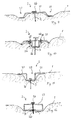
- FIG. 9 a second embodiment of an anchoring profile in a roof structure according to the invention is shown.
- This design of the profile 2 is provided with a central retention portion 21 and two protruding portions 22 on each side thereof.
- anchoring holes 26 are provided.
- the profile 2 is mounted on the fibrous insulation panel 1 and compresses the insulation at the two locations of the protruding profile portions 22 and the anchoring profile 2 is fixed to the support structure (not shown in fig. 9) at the centre of the profile 2, so that the elasticity of the insulation 1 does not tilt the profile 2 once it is mounted.
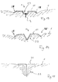
- the embodiment of the anchoring profile 2 shown in fig. 10 is an assembled profile, where the horizontal retention portion 21 is provided in one sub-profile and the inwardly protruding portion 22 is provided in a second sub-profile.
- the two sub-profiles are assembled by suitable means 28, e.g. rivets or bolts.
- suitable means 28 e.g. rivets or bolts.
- Centrally in the symmetry line anchoring holes are provided in both sub-profiles for receiving the anchoring screw 3.
- fig. 11 a variant of the profile 2 of figures 2 to 8 is shown, where no side edge portions are provided. This profile 2 of fig. 11 is more simple and suitable if less stiffness is required.
- FIG. 12 A further embodiment of an anchoring profile for a roof structure according to the invention is shown in fig. 12.
- a metal strip 27 is bent into a substantially rectangular shape and provided with centrally disposed anchoring holes 26 for mounting the profile 2 in the roof structure.
- the basic functions of the retention portion (positioning) and the protruding portions (bending strength) are integrated into the rectangular profile shape.
- a further embodiment is shown in fig. 13, where the protruding portion 22 is semicylindrical in shape.
- the protruding portion 22 may be wedge-shaped.
- the profile may be T-shaped as shown in fig. 15.
- the anchoring holes 26 of the anchoring profiles 2 in the figures are circular in shape. However, it is realised that elongated openings or slits may be provided. This provides the advantage of preventing thermal expansion to cause stress on the anchoring screws.
- the invention is described with relation to a double layer roof structure, i.e. where the upper section of the roof structure comprises a metal roof or the like, e.g. a trapezium/corrugated sheet.
- the invention may also concern any other top roof construction.
- the roof structure according to the invention may be used for vertical structures, i.e. side or end walls of a building, flat roofs or inclined roof structures.
Landscapes
- Engineering & Computer Science (AREA)
- Architecture (AREA)
- Civil Engineering (AREA)
- Structural Engineering (AREA)
- Mechanical Engineering (AREA)
- Roof Covering Using Slabs Or Stiff Sheets (AREA)
Priority Applications (3)
| Application Number | Priority Date | Filing Date | Title |
|---|---|---|---|
| EP04077722A EP1645698A1 (fr) | 2004-10-05 | 2004-10-05 | Une structure de toit |
| EP05786599A EP1815083A1 (fr) | 2004-10-05 | 2005-09-28 | Une structure de toit |
| PCT/DK2005/000612 WO2006037324A1 (fr) | 2004-10-05 | 2005-09-28 | Structure de toiture |
Applications Claiming Priority (1)
| Application Number | Priority Date | Filing Date | Title |
|---|---|---|---|
| EP04077722A EP1645698A1 (fr) | 2004-10-05 | 2004-10-05 | Une structure de toit |
Publications (1)
| Publication Number | Publication Date |
|---|---|
| EP1645698A1 true EP1645698A1 (fr) | 2006-04-12 |
Family
ID=34928548
Family Applications (2)
| Application Number | Title | Priority Date | Filing Date |
|---|---|---|---|
| EP04077722A Withdrawn EP1645698A1 (fr) | 2004-10-05 | 2004-10-05 | Une structure de toit |
| EP05786599A Withdrawn EP1815083A1 (fr) | 2004-10-05 | 2005-09-28 | Une structure de toit |
Family Applications After (1)
| Application Number | Title | Priority Date | Filing Date |
|---|---|---|---|
| EP05786599A Withdrawn EP1815083A1 (fr) | 2004-10-05 | 2005-09-28 | Une structure de toit |
Country Status (2)
| Country | Link |
|---|---|
| EP (2) | EP1645698A1 (fr) |
| WO (1) | WO2006037324A1 (fr) |
Cited By (3)
| Publication number | Priority date | Publication date | Assignee | Title |
|---|---|---|---|---|
| CN107869218A (zh) * | 2017-11-30 | 2018-04-03 | 上海宝冶集团有限公司 | Imax影院多层材料组合屋面的隔声处理方法 |
| EP3851608A2 (fr) | 2020-01-17 | 2021-07-21 | Onduline | Procédé de réalisation d'une couverture de toiture d'un bâtiment et ensemble d'éléments adaptés |
| EP4644633A1 (fr) * | 2024-04-30 | 2025-11-05 | Stiferite S.P.A. | Toiture isolée, plate ou inclinée, pour la construction |
Citations (10)
| Publication number | Priority date | Publication date | Assignee | Title |
|---|---|---|---|---|
| EP0011202A1 (fr) * | 1978-11-17 | 1980-05-28 | H.H. Robertson Company | Fixation d'éléments de construction pour murs ou toits |
| FR2702542A1 (fr) * | 1993-03-09 | 1994-09-16 | Couvracier Sa | Enveloppe isolante et acoustique du type double peau. |
| EP0685612A1 (fr) | 1994-05-30 | 1995-12-06 | Gerthold Dipl.-Ing. Pröckl | Garniture pour systèmes de toit à double couche |
| WO1997036035A1 (fr) | 1996-03-25 | 1997-10-02 | Rockwool International A/S | Procede et appareil de fabrication de panneaux de fibres minerales |
| EP0984114A2 (fr) * | 1998-09-03 | 2000-03-08 | Deutsche Rockwool Mineralwoll-GmbH | Système de toiture à deux couches |
| EP1179645A2 (fr) * | 1997-08-07 | 2002-02-13 | Saint-Gobain Isover | Panneau du mur |
| WO2003016652A1 (fr) | 2001-08-15 | 2003-02-27 | Corus Bausysteme Gmbh | Sous-structure pour toit ou façade |
| WO2003042445A1 (fr) | 2001-11-14 | 2003-05-22 | Rockwool International A/S | Matelas en fibres minerales |
| EP1333131A1 (fr) * | 2002-01-30 | 2003-08-06 | Architectural Profiles Limited | Revêtement |
| FR2849884A1 (fr) * | 2003-01-13 | 2004-07-16 | Corus Bausysteme Gmbh | Sous-structure pour toiture ou facade. |
-
2004
- 2004-10-05 EP EP04077722A patent/EP1645698A1/fr not_active Withdrawn
-
2005
- 2005-09-28 WO PCT/DK2005/000612 patent/WO2006037324A1/fr not_active Ceased
- 2005-09-28 EP EP05786599A patent/EP1815083A1/fr not_active Withdrawn
Patent Citations (10)
| Publication number | Priority date | Publication date | Assignee | Title |
|---|---|---|---|---|
| EP0011202A1 (fr) * | 1978-11-17 | 1980-05-28 | H.H. Robertson Company | Fixation d'éléments de construction pour murs ou toits |
| FR2702542A1 (fr) * | 1993-03-09 | 1994-09-16 | Couvracier Sa | Enveloppe isolante et acoustique du type double peau. |
| EP0685612A1 (fr) | 1994-05-30 | 1995-12-06 | Gerthold Dipl.-Ing. Pröckl | Garniture pour systèmes de toit à double couche |
| WO1997036035A1 (fr) | 1996-03-25 | 1997-10-02 | Rockwool International A/S | Procede et appareil de fabrication de panneaux de fibres minerales |
| EP1179645A2 (fr) * | 1997-08-07 | 2002-02-13 | Saint-Gobain Isover | Panneau du mur |
| EP0984114A2 (fr) * | 1998-09-03 | 2000-03-08 | Deutsche Rockwool Mineralwoll-GmbH | Système de toiture à deux couches |
| WO2003016652A1 (fr) | 2001-08-15 | 2003-02-27 | Corus Bausysteme Gmbh | Sous-structure pour toit ou façade |
| WO2003042445A1 (fr) | 2001-11-14 | 2003-05-22 | Rockwool International A/S | Matelas en fibres minerales |
| EP1333131A1 (fr) * | 2002-01-30 | 2003-08-06 | Architectural Profiles Limited | Revêtement |
| FR2849884A1 (fr) * | 2003-01-13 | 2004-07-16 | Corus Bausysteme Gmbh | Sous-structure pour toiture ou facade. |
Cited By (5)
| Publication number | Priority date | Publication date | Assignee | Title |
|---|---|---|---|---|
| CN107869218A (zh) * | 2017-11-30 | 2018-04-03 | 上海宝冶集团有限公司 | Imax影院多层材料组合屋面的隔声处理方法 |
| EP3851608A2 (fr) | 2020-01-17 | 2021-07-21 | Onduline | Procédé de réalisation d'une couverture de toiture d'un bâtiment et ensemble d'éléments adaptés |
| FR3106351A1 (fr) * | 2020-01-17 | 2021-07-23 | Onduline | Procédé de réalisation d’une couverture de toiture d’un bâtiment et ensemble d’éléments adaptés. |
| EP3851608A3 (fr) * | 2020-01-17 | 2021-09-22 | Onduline | Procédé de réalisation d'une couverture de toiture d'un bâtiment et ensemble d'éléments adaptés |
| EP4644633A1 (fr) * | 2024-04-30 | 2025-11-05 | Stiferite S.P.A. | Toiture isolée, plate ou inclinée, pour la construction |
Also Published As
| Publication number | Publication date |
|---|---|
| WO2006037324A1 (fr) | 2006-04-13 |
| EP1815083A1 (fr) | 2007-08-08 |
Similar Documents
| Publication | Publication Date | Title |
|---|---|---|
| EP1989362B1 (fr) | Système d'isolation comprenant des panneaux d'isolation interconnectés disposés contre un mur | |
| EP2920382B1 (fr) | Système mural isolant pour structure de bâtiment | |
| US20060059847A1 (en) | Bracket for concrete forms | |
| US8863463B2 (en) | Insulation building system for a building structure | |
| JPH06212742A (ja) | 縦葺き屋根構造 | |
| US6860076B2 (en) | Covering arrangement for a building, and covering part for use in such a covering arrangement | |
| EP1815083A1 (fr) | Une structure de toit | |
| EP1169527B1 (fr) | Element de construction de batiment et plaque de renfort con ue pour cet element | |
| JP2002276071A (ja) | 断熱pcコンクリート板及びその製造方法 | |
| JP3061107B2 (ja) | 建築物の横葺外装構造 | |
| CN114144560A (zh) | 墙体建筑元件系统和用于该系统的建筑元件 | |
| US20080229693A1 (en) | Holding element for an insulating panel | |
| US20140202101A1 (en) | Roof structure | |
| WO1998028501A1 (fr) | Element d'isolation destine a etre installe par serrage entre des chevrons de toits ou des poutres d'autres constructions en bois | |
| AU2009233686B2 (en) | Roof Structure | |
| DK2449185T3 (en) | ADDITIONAL INSULATION SYSTEM AND A PROCEDURE FOR INSULATING A FACADE | |
| EP4553405A1 (fr) | Système de montage pour le montage sur un feutre de toiture ou sur des toits à membrane et utilisation d'un tel système de montage | |
| EP4644633A1 (fr) | Toiture isolée, plate ou inclinée, pour la construction | |
| EP3816365B1 (fr) | Rail d'ancrage et système d'ancrage pour parois isolées | |
| WO2011137910A1 (fr) | Système de façade comportant des éléments d'isolation | |
| JP3061113B2 (ja) | 断熱下地材とこれを使用した断熱外装構造 | |
| JP2000282631A (ja) | 横葺き外装構造 | |
| JP3822204B2 (ja) | 棟構造 | |
| JP2909887B2 (ja) | 建築物の外装構造 | |
| RU2774529C2 (ru) | Наклонная теплоизолирующая конструкция и способ ее установки |
Legal Events
| Date | Code | Title | Description |
|---|---|---|---|
| PUAI | Public reference made under article 153(3) epc to a published international application that has entered the european phase |
Free format text: ORIGINAL CODE: 0009012 |
|
| AK | Designated contracting states |
Kind code of ref document: A1 Designated state(s): AT BE BG CH CY CZ DE DK EE ES FI FR GB GR HU IE IT LI LU MC NL PL PT RO SE SI SK TR |
|
| AX | Request for extension of the european patent |
Extension state: AL HR LT LV MK |
|
| AKX | Designation fees paid | ||
| REG | Reference to a national code |
Ref country code: DE Ref legal event code: 8566 |
|
| STAA | Information on the status of an ep patent application or granted ep patent |
Free format text: STATUS: THE APPLICATION IS DEEMED TO BE WITHDRAWN |
|
| 18D | Application deemed to be withdrawn |
Effective date: 20061013 |